Category Archives: DIY UNDERWATER housings

The housing must go to at least 30 meters water depth, for at least a year, and be made from inexpensive PVC fittings & parts that can be obtained anywhere.

A DIY Pressure Chamber to Test Underwater Housings

Pressure testing has been on the to-do list for ages, but the rating on the PVC parts in our older housings meant we weren’t likely to have any issues. However, the new two-part mini-loggers fit inside a thin walled falcon tube, which raised the question of how to test them. There are a few hyperbaric test chamber tutorials floating around the web, and we made use of one built from a scuba tank back at the start of the project, but I wanted something a less beefy, and easier to cobble together from hardware store parts. Fortunately Brian Davis, a fellow maker & educator, sent a photo of an old water filter housing he’d salvaged for use with projects that needed pressure tests. Residential water supply ranges from 45 to 80 psi so could replicate conditions down to 55m. That’s good for most of our deployments and certainly farther than I was expecting those little centrifuge tubes to go.

This mini pressure chamber was made from a Geekpure 4.5″x10″ water filter housing, 2x male-male couplers, a garden tap, & a pressure gauge with a bicycle pump inlet. (~$70 for this combination) The relief valve & o-ring required silicone grease to maintain pressure.

I first tested 50mL ‘Nunc’ tubes from Thermo. These are spec’d to 14psi/1atm, but that’s a rating under tension from the inside. I put indicator desiccant into each tube so small/slow leaks would be easy to see and used a small bicycle pump to increase the pressure by 5psi per day. These tubes started failing at 25psi, with 100% failure just over 30psi. Multiple small stress fractures occurred before the final longitudinal crack which produced an audible ‘pop’ – often four or more hours after the last pressure increase. If 20psi is the max ‘safe’ depth for these tubes then the 50mL tubes can deployed to about 10m with some safety margin for tides, etc. This result matches our experience with these tubes as we often use them to gab water samples while diving.

[Click photos to enlarge]

As expected, the self-standing 30mL tubes proved significantly more resistant. All of them made it to 45psi and then progressed through various amounts of bending/cracking up to 100% failure at 55psi. Where the caps were reinforced (by JB weld potting a sensor module) the rim threads of the cap sometimes split before the tube itself collapsed:

Silicone grease was added to some of the caps although none of the dry ones leaked before the bodies cracked.

So the 30mL tubes have a deployment range to 25m with a good safety margin. The plastic of these tubes was somewhat more flexible with some crushing almost flat without leaks. This implies we might be able take these a little deeper with an internal reinforcement ring (?)

The next experiment was to try filling the tubes with mineral oil to see how much range extension that provides:

A third logger was submerged using only a sample bag:

The bag was included to test the ‘naked’ DS3231 & 328p chips. We’ve had IC sensors fail under pressure before (even when potted in epoxy ) Although it’s possible the encapsulation itself was converting the pressure into other torsional forces that wouldn’t have occurred if the pressure was equally distributed.

Again we moved in 5 psi increments up to 80 psi – which is the limit of what I can generate with my little bicycle pump. At 50psi some mineral oil seeped from the bag and at 70psi the ~1cm of air I’d left in the 50mL tube caused similar leakage. On future tests I will spend more time to get rid of all the bubbles before sealing the housings.

At 70psi the 50mL tube dented & sank and the lid started seeping oil (but did not crack)

The loggers continued blinking away for several days at 70, 75 & 80psi, but eventually curiosity got the best of me so I terminated the run. We were also getting uncomfortably close to the 90psi maximum test pressure on that polycarbonate filter housing. I was hoping to have some weird artifacts to spice up this post but no matter how hard I squint there really were no noticeable effects in the data at any of the pressure transitions – basically nothing interesting happened. I thought the resistive sensors would be affected but the RTC & NTC temperature logs have no divergence. The LDR looks exactly like a normal LDR record with no changes to the max/mins outside of normal variation. The battery curves are smooth and essentially indistinguishable from ‘dry’ bookshelf tests on the same cells. But I guess in this kind of experiment success is supposed to be boring… right? With mineral oil these little guys can go anywhere I can dive them to – even if the ‘housing’ is little more than a plastic bag.

One thing of note did happen after I removed the loggers from the chamber: I accidentally dropped the 30ml logger on the counter while retrieving it from the chamber and a thin white wisp of ‘something’ started swirling around the clear fluid inside the logger. This developed slowly and my first guess was that the capacitor had cracked and was leaking (?)

By the time I managed to capture this photo, the fine ‘smoke’ seen earlier had coalesced into a larger foam of decompression bubbles.

After emptying that oil, the logger itself went into a red D13 flashing BOD loop for a while but by the time I’d cleaned it up enough to check the rail, the battery had returned to it’s nominal 3v. My theory is a similar off-gassing event was happening inside the battery – briefly causing a droop below the 2.7v BOD threshold. So it’s possible that while the loggers are not depth limited per se using mineral oil, components like the separator in a battery may still be vulnerable to ‘rate-of-change’ damage. After more than two weeks at depth, I had vented the chamber in less than a minute. Of course when retrieving loggers in the real world I’d have to do my own safety stops, so this hazard may only affect loggers that get deployed/retrieved on a drop line.

I’ll run these loggers on the bookshelf for a while to see if any other odd behaviors develop. After that it will be interesting to see how well I can clean them in a bath of isopropyl (?) as I suspect that the mineral oil penetrated deep into those circuit board layers.

Addendum: 2023-05-30

Although the units sleep current was the same as before the pressure testing, the battery in the 30mL tube barely made another twelve hours on the bookshelf before the voltage dropped again – well before the expected remaining run time. So it’s a safe bet that any deployment which exposes coin cells to pressure at depth is a one-shot run. Given how cheap these batteries are, that’s pretty much a given when deploying these little loggers even if they remain dry.

Addendum: 2023-12-01

Short 30ml tubes work well for single-sensor applications, but classroom labs needed to switch between different sensor modules easily. So we added 3D printed rails holding mini breadboards to provide this flexibility, and the 50mL centrifuge tubes provide the space for these additions. They may not have the same depth range, but they are robust enough for most student experiments.

It’s also worth noting that these tests were done with the standard ‘plug-style’ caps that come with the NUNC 50ml centrifuge tubes. A few companies make tubes  with an O-ring integrated into the cap (made of silicone or ethylene propylene) which gets compressed when the threads are tightened. Those would provide another layer of moisture resistance at that seal, although they wouldn’t do much to prevent the crush-failures. Unfortunately the Nalgene Oak Ridge high-speed polycarbonate centrifuge tubes that could resist those forces have necks pinched-in to a diameter too small for the modules in our logger.

Waterproofing your Electronics Project

We’ve been deploying our loggers under water since 2013 and although we’ve posted many detailed build tutorials along the way, it’s time to gather some of that distributed material into a summary of the techniques we use. This post will focus on options available with a modest budget and also include a few interesting methods we haven’t tried yet for reference. To put all this in context; we deploy our DIY loggers to typical sport diving depths and usually get solid multi-year operation from our underwater units.

Jump links to the sections of this post:

Arielle Ginsberg examines the sponges covering a flow sensor deployed in a coastal outflow canyon.

Sealants

No matter what coating you use, everything must be scrupulously clean before it’s applied. Corrosion inducing flux is hydroscopic and there’s always some left hiding underneath those SMD parts – especially on cheap eBay modules. That means scrubbing those boards with alcohol and an old toothbrush, drying them with hot air & cotton swabs, and then handling by the edges afterward. Boards with only solid-state parts (like the ProMini) can be cleaned using an ultrasonic cleaner and 90% isopropyl but NEVER subject MEMS sensors or RTC chips to those vibrations. Polymer based RH sensors like the BME280, or MS5803 pressure sensors with those delicate gel-caps, also get careful treatment. After cleaning, let components dry overnight in a warm place before you coat them with conformal. I clean new modules as soon as they arrive, and store them in sealed containers with desiccant.

This $25 jewelry cleaner gets warm during the 5 -10min it takes to get the worst parts clean so I run this outside to avoid the vapours.

MG Chemicals 422-B Silicone Modified Conformal Coating is the one we’ve used most over the years. Even with a clean board, adhesion to raised ICs can be tricky as surface tension pulls it away from sharp edges. Like most conformals, 422-B fluoresces under UV-A so a hand-held blacklight lets you check if it’s thin at some corner, or if you simply missed a spot. The RC/Drone crowd regularly report on many of the other options on the market like Corrosion-X, Neverwet, KotKing, etc. I’ve never seen a head-to-head test of how well the different conformals stand up over time, but the loggers we’ve retired after 5-6 years in service look pretty clean even though silicone coatings are not water vapour proof. I like the flow characteristics of 422 for our small scale application, though the vapours are nasty enough to make you wonder how much brain damage your project is really worth. You can also just burn the stuff off with a soldering iron if you need to go back for quick modification after its been applied. Conformals can be made from other compounds like acrylic or urethane, and at the top of the market you have vacuum-deposited coatings like Parylene.

Nail polish gets mentioned frequently in the forums and it’s usually a type of nitrocellulose lacquer. While it’s non-conductive and non-corrosive, acetate chemistry is not far off acetone which solvates a lot of stuff. So nail polish may soften some plastics and/or the varnish protecting your PCBs. It might also wipe the lettering off some boards. So the trick is to start with the thinnest layer possible and let that harden completely before applying further coats. Nail polish softens somewhat when heated above 200°C with a hot air gun enabling you to scrape it away if you need to rework something after covering. Overall it’s a good low-budget option that’s less complicated to apply than a UV cured solder mask solution.

One of our many early failures before we decided to use only transparent epoxies. The outer surface of this epoxy was intact; giving no hint of what was happening below.
Some epoxies permit slow water vapour migration leading to corrosion at points with leftover flux. Like the white example above, this potting was still OK at the surface. Both of these two failures pre-date our use of conformal on everything.

You never get 100% coverage so the areas underneath components usually remain unprotected. But coatings really shine as a second line of defence that keeps your logger going when the primary housing suffers minor condensation or makes the unit recoverable after a battery leak. Even when we intend to pot a circuit completely, I still give it a thin coat of conformal to protect it during the week long burn-in test before encapsulation. (If you are using cheap sensors from eBay, expect ~20% infant mortality) Be careful not to let coatings wick onto metal contacts like those inside an SD card module or USB connector and remember to seal the cut edges of that PCB so water can’t creep between the layers.

The delicacy of application required when working with IC sensors means that spray-on coatings are usually a bad idea, but there are exceptions. Paul over at Hackaday reports success using clear acrylic spray paint as a kind of poor man’s Parylene after “comparing the MSDS sheets for ‘real’ acrylic conformal spray coatings, and acrylic paint. All that’s missing is the UV indicator, and the price tag.” He uses this technique in outdoor electrical boxes but the first thing that comes to my mind is coating the screw terminals inside most rain gauges (see photo at end of post), and the exposed bus-bars you see in some climate stations.


Potting / Encapsulation

Hot glue is a quick way to seal one side of pass-through so you can pour liquid epoxy on the other.

Hot-melt Glue: Glue sticks come in a variety of different compounds. But it’s hard to know what’s in the stuff at your local hardware store so my rule of thumb is to just buy the one with a higher melting point. If you are gluing to something with a high thermal mass or a surface that can transfer heat (like copper PC board) the glue will freeze before it bonds. So preheating the item you are working on with a hot air gun before gluing is usually a good idea. I’ve used glue sticks for rough prototypes more times than I can remember, sometimes getting several months out of them before failure in outdoor locations. Cheaper no-name sticks tend to absorb a lot of water(?) and have more trouble sticking to PCB surface coatings. So it’s a temporary solution at best unless you combine it with something more resistant like heat shrink tubing. Add glue to what you’re sleeving, and it will melt and flow when you shrink – effectively a DIY adhesive lined heatshrink:

Here I used leather gloves to squeeze the hot-melt glue inside adhesive lined heat-shrink until it covered the circuit without bubbles. This one lasted ~8 months and then we switched to epoxy fills.

Hot glue is also quite handy for internal stand-offs or just holding parts together if they are too irregularly shaped for double-sided mounting tape to do the job. Isopropyl alcohol helps remove the glue if you need to start over.

Superglue & Baking Soda: These dollar-store items are perfect for sealing & repairing the polymer materials that most waterproof kit is made from. Adam Savage has a great demo of this on YouTube. That gusseting build-up technique is so fast it now accomplishes many of the things I used to do with hot glue. CA glue & spray-on accelerant can also be used to improve the strength of 3D prints, as demonstrated by the ever-mirthful Robert Murray-Smith. The sealed surface of your print can then be written on with a sharpie marker without the black ink bleeding into the PLA layers, although I also use clear mat-finish nail polish for this labeling.

At this scale the viscosity of your encapsulating material is as important as any vapours it might give off. To avoid wicking problems, a ring of ‘dry’ plumbers putty can secure a filter cap over the sensor after the liquid potting compound sets.

Silicone Rubber comes in two basic types: ‘Acid cure’ which smells like vinegar and ‘Neutral cure’ which gives off alcohol while it hardens (often used in fish-tank sealants). Never use acid curing silicone on your projects. Hackaday highlighted a method using Tegderm patches to give silicone encapsulations a professional appearance although you can usually smooth things well enough with a finger dipped in dish detergent. In another Hackaday post on the subject, a commenter recommends avoiding tin-cured RTV silicones in favor of platinum cured which has longer lifespan and less shrinkage. Really thick silicone can take several days to cure but accelerants like corn-starch or reptile calcium powder can cut that to a few hours. It’s also worth knowing that silicones expand/contract significantly with temperature because this can mess with builds using pressure or strain sensors.

The $5 3440 Plano Box housings we use on the classroom loggers stand up to the elements well enough in summer months, but rarely have an adequate seal for the temperature swings in fall or winter. Judging by this post over at AVRfreaks, this is a common issue with most of the premade IP68 rated housings on Ebay/Amazon.

While silicone is waterproof enough for the duration of a dive it is NOT water-vapor proof. I often use GE Silicone II (or kafuter K-705) to seal around the M12 cable glands we use on student projects. However, water vapor eventually gets in when the housings “cool down & suck in moist air” causing condensation on the upper surface. Any container sealed with SR will eventually have an internal relative humidity comparable to the outside air unless your desiccants prevent that from happening. Always use desiccants with color indicator beads so you can see when they need to be replaced. Silica gel desiccant beads bring the air above them down to about 20% RH in 24-48 hours but only if there is enough mass for your volume. The best way to determine how much your build needs is to do test runs logging an RH sensor like the BME280 inside the box with different amounts of desiccant. Old desiccant pouches can be ‘recharged’ overnight in a food dehydrator and used ones can usually be found for ~$10 at your local thrift shop. Dehydrators are also great for reviving old filament if you have a 3d printer.

Liquid Epoxy: If money is no object, then there are industrial options like Scotchcast but many come in packaging that dispenses volumes far too large for a small batch of loggers. The best solution we could find at the start of this project was Loctite’s line of 50mL 2-part epoxies designed for a hand-operated applicator gun. Used guns can be found on eBay and there are plenty of bulk suppliers for the 21-baffle mixing nozzles at 50¢each or less. Loctite E-30CL has performed well over years of salt-water exposure on our PVC housings though it does fog & yellow significantly after about six months. Check the expiry date before buying any epoxy because they harden inside the tube when they get old. I’ve often received epoxies from Amazon that are only a month or two from expiring, so don’t buy too much at one time. And they don’t last long once you crack the seal, so I usually line up several builds to use the entire tube in one session.

A background layer of black EA E-60NC potting compound was used to improve the visual contrast. Once that set a clear acrylic disk was locked into place over the OLED with E-30CL epoxy – taking care to avoid bubbles. The acrylic does not yellow like the epoxy and can be thick enough to protect relatively delicate screens from pressures at depth.

My favorite use of liquid epoxy combines it with heat shrink tubing to make long strings of waterproof sensors:

A short piece of adhesive lined heat shrink seals one end of the clear tube to the cable. Epoxy is added to fill about 1/3 the volume. Then gentle heating shrinks the clear tube from the bottom up until the epoxy just reaches the top. Another adhesive lined ring seals the epoxy at the top of the tube. Then gentle heating of the clear heatshrink contracts it into a smooth cylinder. Extra rings are added to strengthen the ends.

We’ve deployed up to 24 DS18b20 sensors on a single logger running underwater for years – failing eventually when the wires broke inside intact cable jackets because of the bending they received over several deployments. This mounting takes a bit of practice, so have a roll of paper towels nearby before you start pouring and I usually do this over a large garbage can to catch any accidental overflow.

This image shows the typical appearance of E30CL after several months in seawater. The brown dot is a marine organism that bored into the epoxy, but they have never tried to drill through the housing itself… which says something about the toxicity of polyvinyl chloride.

The 2-Part fiberglass resins used for boat repair are another good potting option though they are often opaque with unusual coloration. Low viscosity mixes can be applied with precision using disposable syringes. It’s important that you transfer the stirred resin into a second container before pulling it into the syringe because there’s often a poorly mixed layer stuck to the sides of the first mixing cup. 3D printed shells are often used as casting molds but if all you just need is a rectangular shape then I’d use a LEGO frame lined with plastic food wrap. You can make single-use molds that conform to unusual shaped objects with sheets of modeling clay. When encapsulating large volumes you can make that expensive epoxy go farther with ‘micro-balloon’ fillers made from tiny phenolic or glass spheres. I’ve used old desiccant beads for this many times. Other inert fillers like talc power are sometimes used the lower peak temps during the curing process because fast setting epoxies get quite hot – sometimes too hot to touch. And speaking of heat, all encapsulation methods open the possibility that high power components could cook themselves. So avoid covering any heat sinks when you pot your boards.

Filler / Paste Epoxies: J-B weld is good low-budget option for exposed sensor boards. This two part urethane adhesive bonds well to most plastic surfaces and the filler it carries gives a working consistency somewhere between peanut-butter and thick honey. This is helpful in situations where you want to mount something onto a relatively flat surface like the falcon tubes we use with our 2-part Mini Loggers:

This BMP280 module already has a coating of conformal.
Shift the epoxy to the edges of the sensor with a toothpick

Although the original grey formulation gets it’s color from metal filings it is an electrical insulator. The older style JB weld that comes in two separate tubes is slightly thicker than that sold with an applicator syringe. It’s also worth noting that the stuff really needs at least 24 hours to set – not the 6 hours they claim on the package. There is also a clear version that can be used to protect light sensors, but I’ve yet to field test that in harsh enough conditions to see how it ages:

JB can also be used to secure delicate solder connections.
PTFE tape is a good diffuser if light levels get to high.
Unlike E30CL, clear JB-weld retains all those tiny bubbles.
A JB-weld coated DS18b20 after 6 months in the ocean. Specks of iron-particle rust can be seen, but when I broke away the coating the can underneath was still clean & shiny.

Wax: I haven’t tried this yet but it sounds like it could be fun: Refined paraffin can be purchased in food grade blocks for sealing jars, etc. at most grocery stores and it flows well into small component gaps. It’s also removeable, however the 45°C melting point which makes this possible is too low for outside deployments where I’ve seen loggers reach 65°C under tropical sun. A tougher machinable-wax can be made at home by mixing LDPE (plastic grocery bags) or HDPE (food containers) into an old deep fryer full of paraffin wax. The general recipe is a 4:1 ratio of paraffin to LDPE/HDPE and this raises the melting point enough to withstand summertime heat. Or you could try Carnauba wax which has a melting point above 80°C. You probably want to do partial pours with any wax based approach as shrinkage can be significant. If I had to make something even more heat resistant I’d consider an asphalt-based roofing cement. That’s a one-way trip, but it should last quite a while outside.

If you’re spending company money, it’s worth noting that many professional potting compounds like those from 3M are sold in hot-melt glue stick formats [usually 5/8″(16mm) diameter rather than the more common hobby market 1/2″]. This dramatically reduces waste & mess compared to working with liquid epoxies. Of course, it’s unlikely a DIYer will be able to use them as the applicators alone can set you back $300 to $600 USD. Another factor to consider is the different expansion rates of the circuit you are trying to protect vs the compound you are using for the encapsulation: hard epoxies may cause electrical failures by subjecting components to more stress when the environment is cycled between extreme temperatures. In those cases it is probably better to use softer compounds.


Housings & Connectors

Although 3D printers are now affordable, we still use plumbing for our underwater housings so that others can replicate them with parts from their local hardware store. The design has changed significantly over time but this tutorial video from 2017 still stands as the best overall description of the ‘potting wells’ method we use to mount sensors on those PVC housings. It also shows how to make robust underwater connectors using PEX swivel adapters:

Smooth surfaces on the inside of those wells are scored with a wire brush or rough grit sandpaper before pouring the epoxy. After solvent welding, leave the shells to set overnight before adding epoxy because bad things happen when you mix chemistries. In fact, that’s a good rule for all of things listed in this post. Otherwise that expensive potting compound could turn into a useless rubbery mess. Another important thing to note is that we break the incoming wires with a solder joint that gets encapsulated before the housing penetration. This is more reliable than cable glands because water can’t wick along the wires if the jacket gets compromised. The shell shown in that video uses a Fernco Qwik-Cap as the bottom half of the housing and quite a few Qwik-cap housings have survived years under water although the flexing of that soft polymer limits them to shallower deployments. So these wide-body units get used primarily for drip loggers & surface climate stations. It’s worth noting that water vapour slowly migrates through the plastic knockout cap on the upper surface of our drip counters. So they require fresh desiccants once a year even though the logger could run much longer than that. A reminder that over the time scales needed for environmental monitoring, many materials one thinks of as ‘waterproof’ are not necessarily vapour proof.

For underwater deployments we developed a more compact screw-terminal build that would fit vertically into a 2″ cylindrical body. After many struggles with salt water corrosion we gave up on ‘marine grade’ stainless steel and started using nylon bolts to compress the O-ring. But these need to be tightened aggressively as nylon expands in salt water (we usually pre-soak the bolts overnight in a glass of water before sealing). Nylon expansion has also caused problems with the thick 250lb ties we use to anchor the loggers. In a high humidity environments, cheap nylon zip ties become brittle and break, while expensive industrial ties stretch and become loose. We’re still looking for better options but when you are working under water, you need something that can be deployed quickly.

We’ve tried many different epoxy / mounting combinations on the upper cap of those housings, but with the exception of display screens we stopped using the larger wells for underwater units because the wide flat disk of epoxy flexes too much under pressure. This torsion killed several sensor ICs on deployments below 10m even though the structure remained water-tight.

As our codebase (and my soldering skills) improved we were able to run with fewer batteries – so the loggers became progressively smaller over time. Current housings are made from only two Formufit table leg caps and ~5cm of tubing. The same swivel adapter used in our underwater connector now joins sensor dongles to the housing via threaded plugs. Sensor combinations can be changed easily via the Deans micro connectors we’ve used since the beginning of the project. Though the photo shows two stacked o’rings, we now use shorter bolts and only one. See this post for more details on the construction of this housing.

EPDM O-rings lose much of their elasticity after a couple of years compressed at 20-25m, so for deeper deployments I’d suggest using a more resilient compound. And there are now pre-made metal housing options in the ROV space that didn’t exist at the start of this project. With the dramatic size reduction in recent models, you occasionally find a good deal on older Delrin dive-light housings on eBay. Another interesting option is household water filter housings made from clear acrylic. They were too bulky for our diving installations, but this Sensor Network project at UC Berkeley illustrates their use as surface drifters.


Other Protection Methods

Mineral oil: PC nerds have been overclocking in tanks of mineral oil for ages, so it’s safe at micro-controller voltages. It’s also used inside ROV’s with a flexible diaphragm to compensate for changes in volume under pressure. Usually a short length of Tygon tubing gets filled with oil and stuck out into the water, or the tube can be filled with water and penetrates into the oil-filled housing. We use a similar idea to protect our pressure sensors from salt water:

The MS5803 pressure sensor is epoxied into a 1/2″-3/4″ male PEX adapter and a nitrile finger cot is inserted into the stem of a matching swivel adapter.
The sensor side gets filled to the brim with mineral oil
The two pieces are brought together
Then tighten the compression nut and use a lubricated cotton swab to gently check that the membrane can move freely.

Moving those membrane-protected sensors onto a remote dongle makes it much easier to recover the sensor after a unit gets encrusted with critters. Oil mounts have worked so well protecting those delicate MS58 gel-caps that I’ve now started using this method with regular barometric sensors like the BMP280. This adds thermal lag but there’s no induced offset in the pressure readings provided there’s enough slack in the membrane. Silicone oil is another option, and I’ve been wondering about adding dye so that it’s easier to spot when those membranes eventually fail. I avoid immersing any components with paper elements, like some old electrolytic capacitors, or parts that have holes for venting.

Bio-fouling on one of our loggers deployed in an estuary river. We only got three months of data before the sensor was occluded.
We remove calcareous accretions by letting the housings sit for a few hours in a bucket of dilute muriatic acid. Many of our loggers get this treatment every season.

Cable Protection: For the most part this comes down to either strain relief, or repairing cuts in the cable jacket. Air curing rubbers like Sugru are fantastic for shoring up worn cables where they emerge from a housing though I usually use plumbers epoxy putty for that because I always have it on hand for the housing construction. Sugru is far less effective at repairing cables than something that’s cheaper but less well known: self-fusing rubber electrical sealing tape (often called ‘mastic’ or ‘splicing’ tape). This stuff costs about $5 a roll and has no adhesive: when you wind it around something it sticks to itself so aggressively that it can not be unstuck afterward, yet remains flexible in all directions. This makes it perfect for repairs in the middle of a cable and we’ve seen it last months under water though it quickly becomes brittle under direct sun. And it does the job in places you can’t reach with adhesive lined heat shrink. I usually slap a coat of plasti-dip or liquid electrical tape over top of those repairs. This improves the edge seal and makes the patch look better. Self-fusing tape is also great for bulking out cables that are too thin for an existing cable gland, or combining several wires into a water-tight round-profile bundle for a single gland.

However the best advice I can give is to simply avoid the temptation of soft silicone jacket cables in the first place. Yes, they handle like a dream under water, but you will pay for it in the long run with accidental cuts and hidden wire breaks due to all that flexing. Another hidden gotcha is that silicone compresses at depth which brings the wires closer together – potentially increasing the capacitance of a long bus enough to interfere with sensor handshakes. Our go-to after many years at the game is harder polyurethane jacketed cables (like the ones Omega uses for their thermistors) It’s a pain in the arse to strip & solder, but you can pretty much drive a truck over it. And somehow that kind of thing always happens at least once during a field season.

Lost count of how many times ants/wasps have bunged up our rain gauges. And I should have coated those screws…

Double housings: Instead of sealing the housing to block out humidity, control the point where it condenses by surrounding an inner plastic housing with a second outer shell made of aluminum. Then let everything breathe naturally with the idea that condensation will happen first on the faster cooling aluminum, thereby protecting the inner components. I’ve heard of this being used for larger commercial monitoring stations but I’ve never been brave enough to try it myself. You want some kind of breathable fabric membrane over any vent holes to keep out dust (to IP6) and especially insects because if there’s a way into your housing they will find it and move in. Another simple but related trick is to fill any void spaces inside your housing with blocks of styrofoam: this minimizes the total volume of air exchanged when the temperature swings.

Addendum: Testing Underwater Housings

People reading this post might also be interested in the DIY pressure chamber which we’ve been using to test our little falcon tube loggers. It’s made from a household water filter canister, with a total cost of about $70usd. The domestic water pressure range of 40-80psi overlaps nicely with sport diving depths. The 30mL tubes are stronger for single sensor builds, but the 50mL tube provide more space for our 2-Module classroom data logger. This model uses two mini breadboards for convenient sensor swaps.

Addendum: 3D printed housings

PLA (or poly-lactic acid) is made from glucose that is converted to lactic acid with an H2O molecule removed to trigger the polymerization process. While water doesn’t degrade most printable polymers PLA slowly gets brittle when wet because it recaptures the H2O. But there is an energy barrier that requires the right temperature, pH, or UV conditions. Bacteria can also accelerate that chemistry and just anecdotally we’ve seen biofilms grow much faster on prints deployed to wet environments compared to our PVC housings. But it’s impossible to distinguish if it’s the polymer or some other lubricant/additive in the mix that they are attracted to. We’ve also seen ‘compression/tension’ mechanisms in PLA fail because of reduced strength even though there was no visual indications that the parts had degraded. This has motivated of our increasing conversion over to PETG for installations although I still use PLA while a new design is being developed because it prints faster. Most polymers are about 1.25 grams per cubic centimeter, so around 85% infill gives neutral buoyancy in water. Nylon can absorb a great deal of water and swell making submerged prints unusable.

The first thing to do when printing a housing is to make sure your filament is bone dry before starting, but all 3D prints are still going to be porous to some extent. There’s an interesting article on 3-d printed underwater housings over at the Prusa Research blog. The initial strategy is to increase the flow rate and temperature so less air gets trapped between the polymer lines that get laid down by the nozzle. Then I’d try a coating of CA glue with spray on accelerant to seal the outer surfaces. Or you could switch to SLA resin printing like RCtestflight – even then they still filled the space around their servos with silicone grease. Our little loggers work fine immersed in mineral oil which is relatively easy to clean up later with alcohol. Ironing produces smooth flat layers that you would think are more water resistant, but this Reddit contributor found that once bubbles are in the print, they can not be removed by ironing. ‘Brick layers’ would help reduce the air gaps but unfortunately that technique is tied up with patent issues. CPS drone had excellent results making prints waterproof by treating them with Dichtol AM Hydro which is very low-viscosity specifically for impregnation and sealing. This makes me think about testing the many waterproofing sealers at my local hardware store. Multiple thin coats of an epoxy should create an external seal if they get sanded between coats, but the underlying print would have to be strong enough to resist deforming & cracking. CPS also created interesting epoxy & print combination endcaps. Pass throughs are critical weak points in any design because water under pressure can rapidly wick between multi-strand wires if the outer insulation gets cut. Stripping to raw copper and embedding in the epoxy is usually required and you need to add soldered break-point or even a solid wire bridge through the housing because there is no way to get the epoxy to fill all the spaces between the strands without a vacuum chamber. Gyroid fills form continuous tubes that you can pour something like glass fiber-filled epoxy into for strength but heat from the curing resin can cause deformation. Re-melting the prints with powdered salt also seems to work for both water and gas hardening. Even if you eventually get all the bubbles out, the polymers themselves still have a vapour penetration rate. This is an issue in labs where you can’t do isotopic analysis on samples that have been left in poly centrifuge tubes too long. And it’s not unusual for 15ml Eppendorf’s to loose 1/3 of their volume in 8 months even if they are sealed well. If you have the budget for SLA printing, Formlabs have posted an interesting design where the o-ring seals are directly printed into the parts and the enclosure is sealed using a hand-screwed bezel. This is much like the seal you find in PVC plumbing parts like non-glued unions.

Slant3d demonstrated an interesting idea for enclosure boxes that keep water out without a seal although in our project condensation of ambient humidity is equally damaging in the long term. 3D printing is also handy for making angular connection joints for complex protective structures or custom sensor mounts that have to last underwater without rusting. But sometimes in the field you are better off using plumbers putty for those PVC tripods. I’ve lost count of how many times I jury-rigged something on site with plumbers putty that then lasted for years of outdoor exposure.

DIY Data Logger Housing from PVC parts (2020 update)

Basic concept: two table leg caps held together with 3″ 1/4-20 bolts & 332 EPDM o-ring. Internal length is 2x3cm for the caps + about 5mm for each o-ring. SS bolts work fine dry, but we use nylon in salt water due to corrosion; tightening the bolts enough that the o-rings will expand to compensate for nylons 2-3% length expansion when hydrated. PVC is another good bolt material option if you deploy in harsh environments.

We’ve been building our underwater housings from 2″ Formufit Table Screw Caps since 2015. Those housings have proven robust on multi year deployments to 50m. While that’s a respectable record for DIY kit, we probably over-shot the mark for the kind of surface & shallow water environments that typical logger builders are aiming for.

The additional RTC & SD power control steps that we’ve added to the basic ‘logger stack’ since 2017 are now bringing typical sleep currents below 25μA.  So the extra batteries our original ‘long-tube’ design can accommodate are rarely needed. (described in Fig. A1 ‘Exploded view’ at the end of the Sensors paperIn fact, pressure sensors often expire before power runs out on even a single set of 2xAA lithium cells.

This raises the possibility of reducing the overall size of the housing, while addressing the problem that some were having drilling out the slip ring in that design. Any time I can reduce the amount of solvent welding is an improvement, as those chemicals are nasty:
(click to enlarge)

Basic components of the  smaller 2020 housing cost about $10. O-rings shown  are 332 3/16″width 2 3/8″ID x 2 3/4″OD EPDM (or other compound )

Double sided tape attaches a 2xAA battery pack to the logger stack from 2017 ( w MIC5205 reg. removed, unit runs on 2x Lithium AA batteries)

The o-ring backer tube does not need to be solvent welded. Cut ~5cm for 1-ring build, & 5.5cm for a 2-ring. Leaving ~1.5cm head-space for wires in the top cap.

The logger stack fits snugly into the 5.5cm backer tube with room for a 2 gram desiccant pack down the side.

The screw-terminal board is only 5.5cm long, but the 2x AA battery stack is just under 6cm long.  With shorter AAA cells you can use only one o-ring.

With several 4-pin Deans micro-plug breakouts & AA batteries things get a bit tight with one o-ring. So I add a second o-ring for more interior space.

Sand away any logos or casting sprues on the plugs & clamp the pass-through fitting to the upper cap for at least 4 hours to make sure the solvent weld is really solid. (I usually leave them overnight) Then wet-sand the large O-ring seat to about 800 grit.  Sensor connections are threaded 1/2″ NPT, but I use a slip fit for the indicator LED, which gets potted in clear Loctite E30-CL epoxy w silica desiccant beads as filler. Most clear epoxies will yellow over time with salt water exposure, so for optical sensors or display screens I usually add an acrylic disk at the upper surface.

The only real challenge in this build is solvent welding the pass through ports. In the 2017 build video we describe connectors with pigtails epoxied to the housing.  But you don’t necessarily need that level of hardening for shallow / surface deployments. The potted sensor connections shown in the video (& our connectors tutorial) can be threaded directly to the logger body via 1/2 threaded NTP male plugs. 

Note: Position the NPT risers on the caps directly opposite the bolt struts, and as near to the edges of the cap as you can so that there is enough separation distance to spin the lock down nuts on your sensor dongles. In the photos below I had the pass-through in line with the struts, but with long bolts this may limit your finger room when tightening the sensor cable swivel nuts. These direct-to-housing connections do make the unit somewhat more vulnerable to failures at the cone washer, or cuts in the PUR insulating jacket of the sensor dongle.

Threaded bulkhead pass-throughs get drilled out with a 1/2″ bit. Alignment with bolt struts shown here is suboptimal.

This closeup shows a slight gap near the center – I could have done a better job sanding the base of the NPT to make it completely flat before gluing & clamping!

the pass through style sensor cap mates to the the lower half of the housing. We’ve always used our o-rings “dry” on these pvc housings.

I describe the creation of the sensor dongles with pex swivel connectors in the 2017 build video series.

Dongle wires need to be at least 6cm long to pass completely through the cap.

“2-Cap” housing: Aim for 5 to 15% o-ring compression but stop if there is too much bending in the PVC struts.

It’s also worth noting that there are situations where it’s a good idea to have another connector to break the line between the sensor and the logger. (shown in 2017)  We often mount rain gauges on top of buildings with 10-20m of cable – so we aren’t going to haul the whole thing in just to service the logger. But on-hull connections like the ones shown with this new housing necessarily open the body cavity to moisture when you disconnect a sensor, and nothing makes a tropical rainstorm more likely to occur during fieldwork than disconnecting the loggers that were supposed to be measuring rainfall.

With a double o-ring and additional seal(s) in the cap, we probably won’t be deploying this new design past ~10m. Given how quickly they can be made, this short body will be a standard for the next few years; perhaps by then those fancy resin printers will be cheap enough for regular DIY builders to start using them – at least for shallow water work.  For now we’ll continue with the long body style for deeper deployments or remote locations that we might not get to again for a long time. The second o-ring is not really necessary if you make a nice tight stack when you assemble the logger.

In general I’d say these ‘plumbing part’ housings reach their long term deployment limit at about ~60m because the the flat end caps starts blowing noticeably at that depth. That overlaps nicely with the limit of standard sport diving, but if your research needs more depth it’s worth looking into the aluminum body tubes/endcaps becoming available in the ROV market. As an example:  Blue robotics makes some interesting enclosures if you need clear acrylic endcaps for camera based work.

(UPDATE: the double o-ring shown in the photo above was required when using 3.5″ bolts. That was a mistake as they tended to extrude easily.  Using shorter 3″ bolts lets you go with only a single o-ring which is gives you a solid seal with no accidental extrusions.)

Addendum 2023-05-25

We needed a way to see how far we could take the new falcon tube loggers and water filter housings are a good solution as the domestic water pressure range of 40-80psi overlaps nicely with sport diving depths. The internal clearance of the filter housing we used is slightly larger than 4.5″ x 9.5″ so could accommodate these older PVC style housings as well:
https://thecavepearlproject.org/2023/05/24/a-diy-pressure-chamber-to-test-housings/

A household water filters make a good low-range pressure chamber.

A DIY Underwater Housing for Arduino Data Loggers made from PVC pipe

Doodles are a fundamental part of the process...

Doodling is a fundamental part of the process…

I spent a great deal of time cutting, sanding and gluing my underwater housings last year. And I learned a heck of allot about adhesives, O-rings, hull penetrations, and potting circuits.   But mostly I learned that I like soldering more than I like cutting…sanding…and gluing PVC. Holiday travel left me with a wicked stomach flu on New Years, so I had a few bedridden days to contemplate all this and think about how I could simplify the design. I was already cutting up Formufit 2″ table caps to provide bolt supports on the 3″ housings, and I just had this sense that I was missing a trick by taking those table adapters apart just to glue the pieces back together again.  Perhaps, if I made the build more compact, I could just use the Formufits as they were?

In all, I probably spent a week, staring into space and sketching ideas, and another week assembling prototypes. But I think I have finally sorted the new Cave Pearl underwater housing design for 2015. The taller unit here has six AA batteries, while the “mini” has only three:

caption

My wife dubbed these “Stormtroopers” because the black details against the white PVC reminded her of those Star Wars characters.  Given how important actual storm events are to data they will be gathering, I’m cool with that 🙂

Boards are held in place with double sided tape

Boards are held in place with 3M double sided tape and the RTC breakout is inverted on 12mm M2 standoffs. This makes it easier to replace the coin cell on units where I power the RTC from a pin on the Arduino, since they will be in battery powered ‘timekeeping’ mode most of the time.

This assembly requires a small number of 2″ pipe cuts,  and only two surfaces need to be wet-sanded for the o-ring seats. Putting all those sensor breakouts under epoxy in the single ring on top lets me juggle the them around, and is more forgiving of different board dimensions than my older designs. I would not have put that much faith in the Loctite E30CL if I had not already seen last years units survive for so long under water. This design requires a very tight build for the electronics, and I don’t think I could have tackled soldering like this when I created the original housings in 2014. Aside from the new 32k eeproms, this is still just a variation of the basic three component logger that I published in July last year. I am simply putting it together on both sides of a .060″ ABS sheet that I bend into shape with a heat gun.

Of course this new design will have to go through the usual round of underwater tests, and I hope that the long nylon bolts act as spoilers for the vortex shedding I am bound to see in the higher flow systems.  I will add some rounded baffles if that becomes too much of a problem.  Even if this design does not prove suitable for the flow meters, it is so quick to assemble that some version of this style will become the standard housing for my other underwater sensors.  There are more variations coming off the bench, and I will post a few of the better ones as they come together, especially ones that let me flexibly extend the housing to hold more batteries for really long deployments.

 Addendum 2015-02-06

This post has only been live for  a few days, and I have already had several offline requests for more information. So here are some details on how I put these housings together, starting with an exploded view of the parts:

Only 2 surfaces (arrows) need to be wet-sanded down to 800 grit for the O-ring seats.

Only two surfaces (arrows) need to be wet-sanded for the O-ring seats. I take it to 800 grit, but 600 would probably be ok. Examine your parts before buying, as brands vary considerably in the number of casting seams & ID information they place on the rims.  To do the least amount of sanding possible, buy the ones with the smoothest finishing, and flip your parts around so that you are not sanding down any edge cuts for o-ring seats.

The pipe is schedule 40 PVC, and the center piece is a standard 2″ coupling. The pvc ring bordered by the arrows is only glued on the coupling side, and it extends into the upper cap only far enough to provide a backer for the o-ring, and to hold the top cap in alignment. The top cap is not glued, but is held in place by the five inch 1/4-20 nylon hex bolts. These bolts are slightly wider than the holes in the Formufit endcaps, so you need to drill them out a bit. But I would suggest that people start their builds with threaded rod, rather than fixed length bolts, as this gives you the freedom to experiment with different lengths of pipe. The o-ring pictured here is a #332 3/16″width 2 3/8″ID x 2 3/4″OD, and its diameter extends slightly outside the PVC (pressure at depth will push them inwards…). A smaller diameter 1/8″-229 also works, and fits inside the seats. I am still trying to find an affordable supplier for 5/32″ cross section o-rings, which would probably be the best size to use. I use Loctite Hysol E-30CL to pot my electronics.  I use the clear epoxy is so that I can see my indicator LED’s and keep track of how the epoxy is aging. But if you replaced that epoxied well of sensors with a clear acrylic disk, you could make camera & light housings for other interesting projects. The only limitations are that everything has to fit inside 2″ PVC pipe, and that those flat Formufit cap ends are only 4 mm thick, affecting the maximum depth they can with withstand.  For now I am expecting these housings to go to at least 100ft/33m safely.

Addendum 2015-02-07

And here is the extendable version of the design:

Just wait till you see what

Each bank of batteries is isolated with a 1N5819 Schottky.  Just wait till you see what I need all this power for . . .

In this version the lower ring of struts (where the white nuts are attached to the 3.5 inch bolts) has the flat surface of the Formufit table cap removed with a hole saw. This turns it into a freely moving slip ring which applies pressure to the bottom of the glued coupling, and thus to the o-ring above it. This build uses a slightly shorter coupling than the initial builds, and the PVC tubing that leads to the rounded end-cap at the bottom can be any length, making room for more boards, etc.  For multi-year deployments, I will probably make stand alone battery compartments this way, connecting them to a separate mcu & sensor housing via my diy underwater connectors.

Addendum 2015-07-23

2inchLoggerPlatformbuildwRocketUltra

The black zip tie (upper left) provides a handle so I can pull the carrier out of the housings.

I have discovered that the long temperature strings really did not need that 12 x AA whopper pictured above, and I now mount the batteries in a power pack module that is physically separate from logger itself. This gives me the added benefit that the batteries can be located further away from the sensor caps, hopefully reducing their influence on the magentometers I use in the flow sensor builds. If I suffer from battery leaks again, I can simply replace the carrier in the field. Should I end up needing a large number of batteries for something in the future, I will just whip up a “Y” adapter cable to connect a couple of these modules in a parallel configuration. The Schottky’s on each bank will keep them from fighting with each other.

Addendum 2015-07-26

And here is the exploded view of the parts for the extendable housing:

Once again only the indicated surfaces need to be sanded. The short 1cm ring and threaded adapter in the lower right corner are optional, depending on how you want to mount your sensors to the top of the unit. I usually put at least one threaded connector on so that I can attach some sort anchor cables to my loggers so that they don't get carried away.

Once again only the indicated surfaces need to be sanded. The short 1cm ring and threaded adapter in the lower right corner are optional, depending on how you want to mount your sensors. I usually put at least one threaded connector on the body so that I can attach some sort anchor cables to my loggers at that point.  The  bolts are just a wee bit bigger than the holes in the Formufit caps – so you will have to drill them out with a 1/4″ bit to let the cap slide freely, and only use nylon if your sensors are sensitive to nearby metal – otherwise go with SS.  The PVC coupling is 4cm wide, and if your couplings are longer the bolts will be too short, and you will need to switch to threaded rod.

Addendum 2016-03-10

As more projects adopt this housing design, many have been asking me about the maximum depth they can withstand, though I have not yet had enough ‘spare’ units to put any through destructive testing. My back of the envelope guess?  The 2″ schedule 40 pvc has a rated operating pressure around 150 psi, so nominally those parts are good to somewhere around 300 feet. So I am confident that we could deploy to about half that, expecting failures to occur first at the solvent welds & hull penetrations. (see pg 69 of the Loctite Plastics Bonding Guide for more info on shear strengths) You would probably need a harder o-ring compound for those depths as well, as the EPDM I am currently using is pretty soft, and would compress significantly below 100ft.  For really deep deployments, you could fill the housing with oil like they do to the motors on ROV’s. Some of those add an ‘external bladder’ with extra oil to balance the internal and external pressure.

We no longer use those large surface area potting – rings shown at the beginning of this post because as you go deeper the epoxy begins to flex, and this ruined some of our temperature sensing IC’s. So keep the diameter of your sensor mounting wells as small as possible, and try to mount the sensors/leds etc. 10mm or more below the epoxy surface.

Bio fouling on estuary unit after 6 months. As you might expect, critters usually kill our pressure sensors before salt water corrosion does.

A researcher over in Europe contacted me while ago when I was using the 3″ end-caps, for a project tracking daily krill migration.  But I have not heard back from him if he was able to go deeper with those thicker, rounded hulls. Our experience is that the PVC housings are unaffected by salt water, and although marine critters will grow on the surface, even boring organisms would rather drill into the loctite epoxy than go through the PVC housings.  We often have to soak the loggers overnight in a muriatic acid solution to dissolve the encrustations before opening the housings.

Addendum 2016-07-31

I just stumbled across an interesting ROV build based on PVC pipe over at instructibles.com that shows just how far you can take this pipes & wires approach. PVC has been a go-to material in the DIY crowd for ages.

Addendum 2016-11-18

“Marine-Grade” 316 stainless steel washers after five months exposure to salt water – after scraping away the ball of brown rust. Whatever the company claims about it’s durability, always cut that number in half.

Just a quick note about those nylon bolts in that photo above.  They expand from their dry length of 94mm to about 96mm when they are wet. This is just enough for them to become loose over  a long underwater deployment unless you over-tighten them considerably going in. We’ve retrieved several loggers where the bolts that were tight when the units were dry, but could be spun freely when then logger came out of the water.  Fortunately the sliding cap design means the O-rings were held shut by the pressure at depth so that seal saved us from data loss.  Our magnetometer flow-sensors are sensitive to the presence of metal, but if your sensor combination is not limited by that I’d suggest you use stainless steel or titanium bolts to hold the housings together.  Or at least soak those nylon bolts in water for a few days before deployment so they are already expanded. Note that the nuts also expand and are hard to release due to the increased diameter of the bolt when everything is wet – give them a day or so to dry out and they become much easier to undo.

Even stainless bolts corrode in seawater eventually, so lately we’ve been using SS bolts, with nylon nuts. That way even if the bolt threads are shot after a year (or two) in salt water, you can open your logger by cutting away the nut with a pair of clippers. Replacement bolts cost less than a fresh set of batteries, so you should probably add a new set of bolts whenever you change the AA cells. 

Addendum 2020-03-01

A quick up date on the progress wrt hull pass-throughs: We’ve been using the sensor pigtails (described on the waterproof connector page) for quite a while now with connector dongles that are potted in E30CL epoxy on the housing body. But that’s overkill for shallow water & surface deployments.  In those cases you can solvent weld threaded NPT connectors to the housing and attach the sensor dongle directly to the housing: (click to enlarge)

For deeper deployments where pressure is significant the hull pass-throughs are hardened with a thick well of epoxy.

For shallow/surface deployments: 1/2 inch threaded NPT connectors can be drilled allowing wires from the sensor dongle to pass through the bulkhead.


Smaller housing made from only two caps (April 2020)

We do observe some pressure-bowing on the flat end-caps below 20m depth even when the wells are filled with epoxy. And since the 1/2 holes necessarily weaken the bulkhead I won’t be deploying direct-connect loggers past 10m if they are made from schedule 40 PVC. With recent advances in power management we’ve also been able to decrease the size of the entire housing.  (w details at @ DIY data-logger Housing from PVC parts)

A Simple DIY Underwater Connector System made from plumbing parts

Up to this point, the Cave Pearls have been self-contained units. But this means that the sensors must be mounted directly on the housings, and the batteries must fit inside.  I already have ideas for new sensors that would require me to overcome these two limitations, so I need to address the issue of how to make electrical connections that are not merely IP68 waterproof, but rugged enough to withstand pressure at depth for a year or more.

I wet-sand the ends (indicated by the red arrows) of that nipple with 600 & 800 grit to smooth away any casting seams.

Wet-sand the ends of that nipple (arrows) with 600 & 800 grit to remove any casting seams. Smooth all o-ring seats.

Use a couple of sizes of heat shrink tube to seal the cable to the pex adapter

On 1/2″ barbs, use a couple of sizes of heat shrink to step down (from Ø12/6 tubing) to the diameter of the cable you are using before sealing the connection with epoxy. Adhesive lined tubing  helps the seal. You can also buy 1/2 NPT x 3/8 PEX adapters for thinner cables, but for some reason they cost twice as much as the larger diameter 1/2 x 1/2″ adapters (?) 

As a diver, I had already seen debates about which connectors are the best on the scuba forums, and a quick Google search quickly finds many suppliers for that market. Most of these are “wet-plugable” connectors encased in delrin/rubber, and they are workhorses in many industrial and military applications. High profile companies like Seacon making a bewildering array of solutions, but their cheapest ones come in around twenty five dollars per socket, so a complete connection will set you back at least $50.


Remove the cone washer before filling adapter with epoxy

Remove the cone washer before filling with epoxy. I score the inside of these 1/2″ barbs with an old 8×125 tap to promote epoxy bonding.

Many of these commercial connectors are rated for deep ocean deployments, able to withstand thousands of psi – far more than I will subject them to in the shallow cave systems. And they often give you a short little pig-tail under the assumption that you will be using it with a cable gland , or a bulkhead connector on a nearby housing ( or at the very least a couple of layers of marine grade adhesive lined heat shrink tubing)  I needed some decent cable runs so I went looking for other applications with longer lines at shallower depths . The pool & underwater lighting folks often use  Bulgin electrical connectors, and the 400 series   Buckaneers  (rated to 10m) occasionally come up on eBay in the $10 range, But again you need to buy two sockets (male&female), and you need to buy the pins which are sold separately. So you still end up around $25 per connection.


Make sure your wires are long enough to extend past the nipple, or you wont be able to make the connection!

Make sure your wires extend all the way through the nipple, or you can’t make the connection! And use soft flexible silicone wires so they fold back into the connector easily.

With all that as background, I went hunting once again through the plumbing section at the local hardware store.  I reasoned that anything that could hold water in, could also hold water out, right?  And I think I have come up with a solution using Nibco pex swivel adapters that is pretty cheap and can be adapted to many different applications. These plumbing adapters are rated to withstand 100 psi, which is roughly equivalent to 230 feet under water.  And that is pressure from the inside out, so my gut feeling is that these things will be able to withstand slightly greater pressure in the other direction, where the forces act to increase the compression of the cone washer.  The thing I like about the swivel adapter mechanism is that it applies pressure to a hard plastic lip on the other side of the washer, so as you tighten the nut there is no rotational force being applied to the parts forming the water tight seal.

And it even looks good!

~$6 for parts, and it looks good too.

These adapters come in a variety of larger & smaller diameters allowing you to use different cable thicknesses, and you can change the length of the pvc riser pipe in the middle to make more space for the internal connectors. This also gives you a way to adjust the amount of air/buoyancy along the run and with a string of connectors this might be a good way to reduce strain on the cable.  I suspect that the schedule 80 tubes in the middle are the weakest point in the system, but filling the internal space with mineral oil would get these connectors to significant depth, as would a filling of paraffin wax, though that would have to be heated again to undo the joint. 

Addendum

TheSimplestDIYUnderwaterConnector

Don’t forget to smooth the seat on that male hose barb side if it has bad casting seams. You want that connection to be as clean as possible. You need to use small connectors for this M-F design.

After building a few of these, I realized that it was possible to make them even simpler if the electrical connectors were small enough.  In the picture here, one side has a Nibco PEX swivel adapter, while the other has a male thread NPT to PEX  adapter. These are both polymer, though it is hard to find an epoxy that will bond to it with an applicator fine enough to put the adhesive into the barb cavity. These fittings are also available in brass for the same price, and the o-ring seats are much cleaner on those than the polymer adapters because there are casting seams on the plastic parts. But I don’t know how well the brass will fare in marine environments. Some of my sensors have stainless shells, so I worry about galvanic effects in salt water?  

After this, pull the cable through so the

Pull these joins into the connector so they are embedded in the epoxy.

In the photo above I’ve used a three wire PC fan connector, and it “just barely” fits inside the cavity of that m/m hose barb. I will use smaller JST connectors in future, or perhaps Dean’s Micro 3pin or 4pin for something more robust.  The internal diameter of the 1/2 pipe is a little over 12mm, so if you need to squeeze more connections in there you could try a couple of “mini micro” JST’s, but I find that soldering all those wires so close together is a bit irritating because it’s easy to accidentally melt the plastic, loosening the tiny pins. 

I also found that the wire inside my cables were too stiff to fold neatly into this much smaller space, so I had to add some flexible 26 AWG silicone wires to the ends. After the jumpers are attached, pull the cable through so that the solder joins get embedded in the epoxy. This has the added benefit of providing a break in the insulation around the wires, so that if you do get a cut in the cable, water can’t work it’s way through the connector by wicking along the copper strands.  I am still hunting for a good supplier of multi-conductor 22-24 awg cable that has a good “handling weight” for underwater applications. It’s hard to shop for something on the internet when what you are really after is something that “feels right” when you hold it in your hands.

A dual connection cap for one of our 2″ underwater housings. We now use harder PUR sheath cables because softer silicone jackets were too easily damaged during deployment dives. For a less expensive option,  Luke Miller has had success using USB cables with his underwater sensors.  A 3/4″ adapter from the pex connector system gives you a way to mount pressure sensors under oil.

I should add the usual provisos here about this being another of my completely experimental ideas so use this at your own risk.  Pex tubing is generally rated to  ~100psi (at temperatures below 74°F) and if the o-rings can withstand that then they should “theoretically” be good to about 60m depth. Translating that into the real world, I expect these connectors to be trustworthy to about 40m, which covers most of our cave deployments.

Addendum 2015-01-30

I just stumbled across a different solution to the expensive underwater connector problem. His method for waterproofing connectors using 3D printed silicone molds is beyond my current capabilities, but its nice to see it explained with such clear documentation.

Addendum 2015-02-01

If those pex adapters don’t have enough room for your cables, I found another great underwater connector project which might do the job for ya 😉

Addendum 2017-01-23

As time goes on I am reducing the number of interconnects, but even with longer chain segments I will probably stick with only 24 sensors per logger.

As time goes on I am reducing the number of interconnects, but even with longer chain segments I will probably stick with only 24 sensors per logger.

Just though I should add an update to mention that quite a few of these connectors have been in service for more than a year on temperature chain deployments. None of them have failed on relatively shallow deployments from 5-15m depth. The only problem I’ve had  is the length of the connector itself can be challenging when you are trying to pack one of those long strings into the mesh bag for an underwater deployment.


Addendum 2018-12-05

I’ve posted a video showing how I build those underwater connectors and use them with epoxy potted sensors:   ( part of our 2017 screw terminal logger series) 

It’s also worth mentioning that you can improve the fit of various parts by taking advantage of the fact that they are thermoplastics:

Rotate & heat the inside corner edge of the tube until ~ 0.5mm of the material ‘softens back’. Don’t over-do it! you don’t want to alter the tube diameter or hurt the threads.

Quickly press the mating o-ring onto the seat while the PVC is still soft enough to conform to the shape.


Before & After heat treatment: the o-rings now form a better seal. This is faster than sanding away any rough casting seams on the parts

Addendum 2020-04-06

These connectors & sensor mounts are part of the housing system we’ve been developing since 2015. You can see the latest underwater housing build @ DIY data-logger Housing from PVC parts

Field Report 2014-08-26: Old Flow Sensor Inspection

The drip sensor deployments left me with an couple of hours free time that evening, which gave me a chance to take a closer look at the flow sensors we pulled the day before.

From the same batch?

Different corrosion  although nuts & bolts were identical

The most obvious impact of the near marine exposure was the rust that had accumulated on the stainless steel bolts and ballast washers. (no spec on the bolts, but the lock nuts were 18-8) While they fasteners were all purchased at the same time, they showed dramatic variation in the amount of oxidization they sustained. I can only presume these are the result of the manufacturing process leaving scratches which acted as nucleation sites. Even the fasteners that suffered significant oxidization remained secure and they were relatively easy to remove once the surface rust had been brushed away.

Still clear, and nothing growing on the surface.

E-30CL still  clear, with nothing growing..

Some pitting on the JB weld surface.

Some pitting on the JB weld surface. I had some concern that the iron particles in the J-B weld might induce galvanic corrosion on the other metal parts.

Both epoxies proved to be far more robust than the manufacturers testing indicated, with the Loctite showing some surface fogging on two units, while remaining perfectly clear on the other one. The grey JB marine weld changed from a smooth surface to one with significant grit (~400 grit sandpaper?). I suspect the pitting is a result of the iron particles in their formulation rusting out of the the matrix, and I will try to get these puppies under a microscope later.  The rubber 0-rings were still in pretty good shape although they had a significant layer of bacterial slime on the exposed surfaces which I cleared off with a touch of isopropl alcohol. I suspect that any material with suflur in it is a banquet for critters the low energy cave environment, but the O-rings certainly look like they will survive for at least a year. (something for me to keep in mind with the bungee anchors though, as the older one’s are at 9 months submersion now)

Three of the four units pulled their 6 x AA power supplies into the 3.3 volt range (as read by the Atmel internal 1.1 vref trick) ; more power drain than my earlier tests had indicated for a 5 month run. But those bench-top tests were done too fast to include self discharge, without isolation diodes, and the real world batteries had been exposed to a relatively high humidity for the duration. (I have added 10 gram desiccant packs to the current crop.)

Perhaps the most interesting power consumption result was from the one unit that included a voltage regulator in the power supply module. I was unable to measure the cell voltage directly till a few days after the units were disconnected, but after the rebound period the AA’s supplying the NCP1402-3.3V Step-Up regulator were at 1.35v, while identical cells that had powered the unregulated Tinyduinos were at 1.4 v.  That’s a pretty small difference given that the nominal efficiency of the regulator is around 75%.

I will have to analyze the rest of the data later because the little net-book I have with me doesn’t have the gumption to chew on data sets of nearly 34000 records. So now we have the three older model Cave Pearls (and a pressure sensor!) cleaned up and in working condition… I think it’s time to put some thought into our next experiment!

Field Report 2014-08-25: Retrieve & Deploy New Flow Sensors

We started the day with breakfast at Turtle Bay Cafe, and once I had enough caffeine in my bloodstream to engage more than two brain cells at the same time, I reviewed the data on the SD cards from the overnight test runs. They all looked good.  Over breakfast we met up with Monika Wnuk, a multimedia journalist and documentary photographer from Northwestern University, who wanted to interview Trish for a water & development story she was working on. Yesterday, when she heard about our abbreviated schedule, she volunteered to help with the sensor preparation, and to provide shore support for our deployment dive. I was glad for the assistance, as two scheduled days were now being merged into one single operation.

Pre-dive planning with Bill, Trish, Monica & Jeff.

Pre-dive planning with Monica, Bil, Trish & Jeff.

Our diving field work almost always begins with a visit to Speleotech in Tulum, to see our long time friend Bil Phillips. Bil taught me to cave dive many years ago, and I still have much to learn from that remarkable man, who is without doubt one of the most dedicated cave explorers in the world. We also had the good fortune of meeting another good friend, Jeff Clark, who loaned me some equipment I needed for the days dive. The dive community in Tulum has always been generous to visiting researchers because they understand, more than most people, what is at risk with the rapid development that is happening in the region.  We all share a passion for protecting the caves as both a vital water resource, and as areas of natural beauty & wonder.

Checking for rotation, damage, etc.

Inspecting the old units for rotation, damage, etc.

With the kit sorted, we headed out to our main deployment site where I began to adjust the buoyancy of the new sensor units. With the new internal copper ring of ballast mass (45g), and heavier
aluminum battery holders, it only took 2-3 external washers to bring each unit to my target of 15 grams negative. This is slightly heavier than the last deployment but I am expecting any reduction in the tilt angle to be more than compensated by the 14bit 1g resolution of the new BMA180 accelerometers.  With
calibration out of the way,  Trish and I set off on the dive. High tide at the coast meant the system was experiencing very low flow, so we had a relaxed swim, with three new pendulums and a pressure sensor stowed neatly in the mesh bag by my side.

Old vs. New

New  vs. Old

Once at the site, the first task was to do a general inspection of the old units, noting anything unusual in my dive notebook.  After almost five months of submersion, there was plenty of rust on the stainless steel bolts and one of the units needed it’s anchor plate replaced.  Using the checklist I had prepared earlier, we swapped each unit in succession with it’s replacement.  In the calm conditions, percolation obscured our view a bit as our bubbles meandered around the ceiling of the cave, but it was still a very simple operation to exchange flow sensors.

Once the new units in place, we did a final inspection swim:

…checking that the new units were secure, with the X axis of the accelerometers oriented toward north.  While this is not strictly necessary with magnetometers inside the units,  I can use it as a rough confirmation of the compass bearings when I get the chance to do some proper data analysis later. I gathered the old sensors into the mesh bag and we made our way out of the cave.  I am not sure I can fully express the excitement that an inventor feels returning from a dive like this, but it’s very, very cool.

I think there is an ocean and a sunset in this picture. But at the time, we did not even notice it.

There is an ocean and a beautiful sunset in this picture. But at the time, I don’t think we even noticed it. (photo courtesy Monika Wnuk)

Back at the surface we had a chance to do a better visual inspection of the old units, which all appeared to be intact. I had some concern about the hull penetrations, as none of the epoxies were rated for long duration marine exposure. But the indicator LEDs were still piping on schedule, telling us that they were all still running.  Back at the dorms, we were equally thrilled to find complete data sets recorded on the SD cards.  (I will post more on the actual data after we have a chance to work on it.)

 <— Click here to continue reading the story—>

Building your sensors & underwater housings from scratch

I reviewed my build journal recently, and found enough themes in there for another bit of bloggy catharsis.  No one should mistake this as the advice of an expert in anything, as I have a long way to go before I start collecting karma points at the playground. But at least I can claim that these ideas are well tested, because as the saying goes, I never make the same mistake twice – I make it 5 or 6 times… just to be sure.

Prototyping:

Only RTC & interrupt lines get soldered to the mcu.

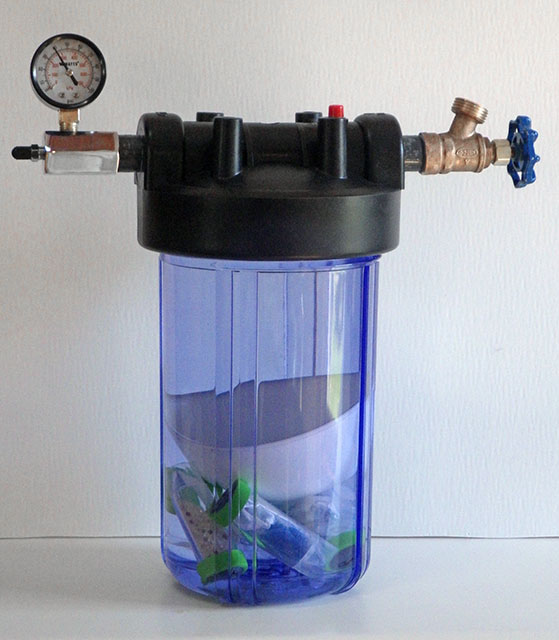
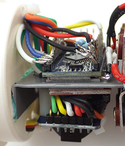
Only RTC, SD, & interrupt lines soldered to the mcu.

Join the forums: Everyone says read the datasheets first….well from this beginners perspective that’s B.S.  Even when I started to understand all the terms I was reading, it was still a major leap of understanding to realize what the information in the data sheet implied… (and I still go through it with each new sensor)  If you want to get rolling on something start with the discussion forums, because it’s likely that someone there has already walked down your path, or one very close to it. Thirty minutes Goggling Sparkfun, Stack Exchange, or searching through places like the Arduino Playground, will get you farther than several hours reading the datasheet. Of course you will eventually end up doing that too...just don’t start there.  Often the forums lead you to some well commented GitHub code examples.  It is so much easier to understand the data sheet, when you have a piece of relevant code in front of you at the same time. Datasheets are written solely for corporate electronics engineers, because unless you represent the 10 to 100 thousand unit MOQ,  you simply don’t show up on company radar.

( Sometimes it even seems that a company deliberately tries to hide the functions built into their own ICs from the maker community.  For example: the mysterious Digital Motion Processor (DMP) functions of the invensense 9150. I have yet to find a single example of an Arduino script accessing these features though the 9150 is commonly used in quad copters. I’d have thought that having Euler angle & 9DOF quaternion calculations done for free, would have drawn some serious attention from those those guys.)

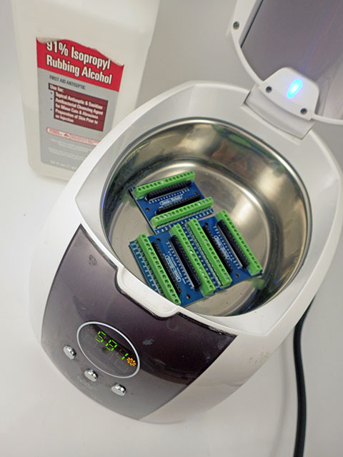
You need one completely “trusted” set of kit:  Which you will pay dearly for, but you need it to test out each new component you are thinking of adding to your project. (I still haul out my original Uno for this from time to time, because the darned thing is virtually indestructible…)

More than a few of the cheap eBay boards are D.O.A.

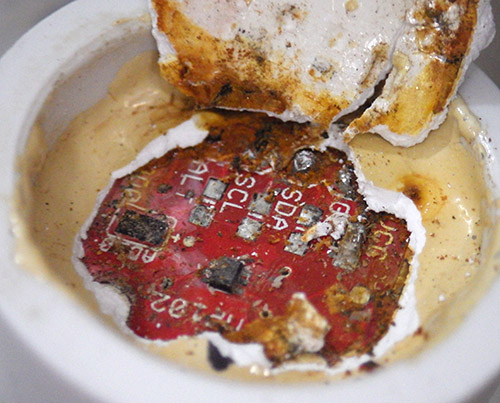
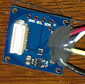
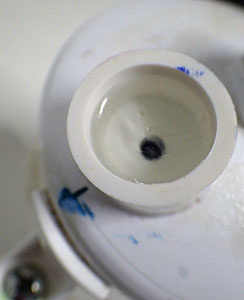
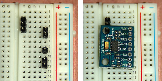
About 1 in 10 of the cheap eBay boards are D.O.A. This  ADXL345 board had a pretty typical alignment skew: X & Y axes were ok, Z did not read.

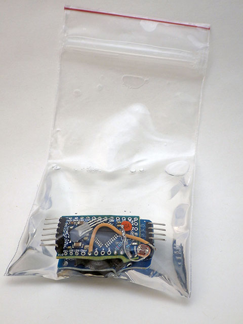
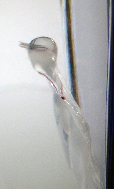
Connect new parts one at a time:  Do not add to your grief by connecting two new untested pieces of equipment to each other at the same time. (like, for example, a new FTDI board, and an Arduino clone of off eBay….grrrrr….) I am slowly learning what it is that you are paying for when a given sensor module sells for $20 from a trusted source like Sparkfun and $2 from China.  It’s probably not the components (although I hear there are fake IC’s out there) but something else that’s just as important.  If you watch the Tiny Circuits promo vid, around the 5 minute mark you see a person manually re-positioning the components that the pick and place machine laid down, and then around 7:15 you see someone testing each board before shipping. At this point I have seen enough of the eBay stuff that I am pretty sure that these two steps are never done on the clone boards. So If you go down that route, you are implicitly agreeing to do those jobs yourself (in addition to cleaning off all the excess flux left on the boards…)  This is not a problem when I am just hacking something together, and then testing it on the bench (or in the bathtub…) but not a risk I will take lightly for the fieldwork units.

And while we are on the topic of those cheap modules, they almost always arrive with connections broken out for both SPI and I2C, but you will likely use them as one or the other, meaning that you often need non adjacent pins soldered onto the breakout. I used to fiddle with crappy metal “helping hands” things (now replaced by a far more effective Panavise Jr)  to get those single pins soldered into place, but now I simply use a bread board to hold the pins in the correct locations before soldering:

Many thanks to my bother Mike for showing me this soldering technique!

Many thanks to my bother for showing me this soldering technique!

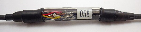
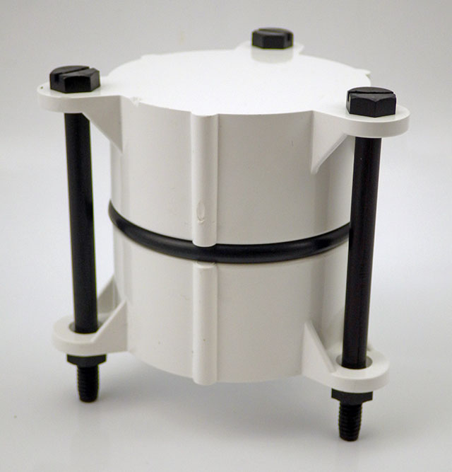
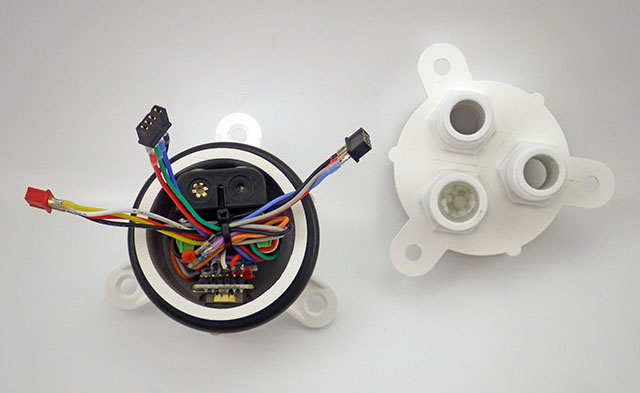
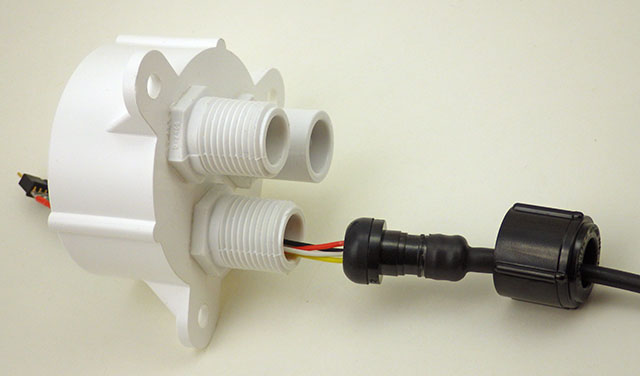
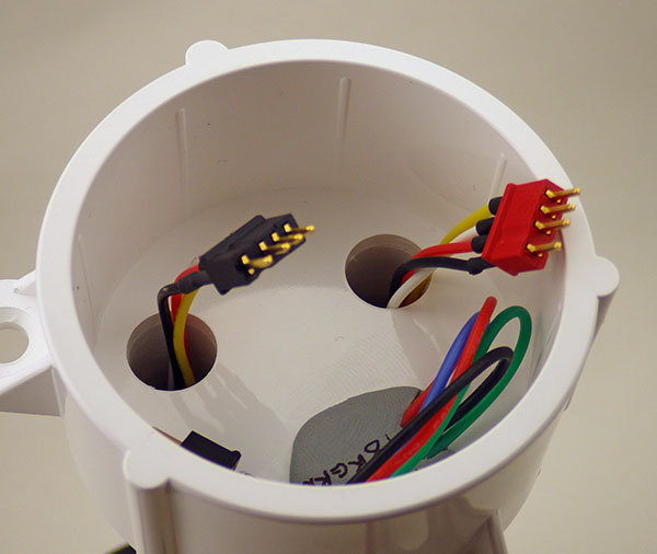
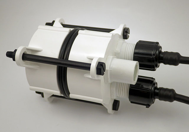
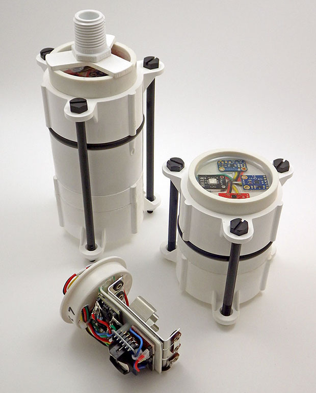
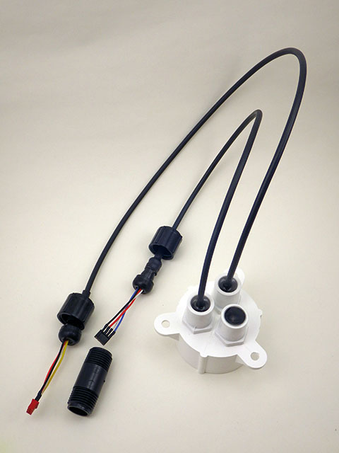
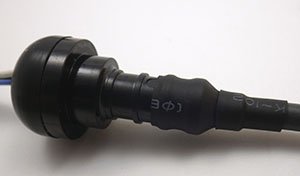
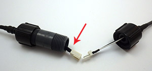
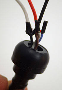
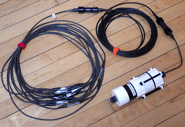
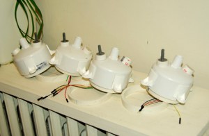
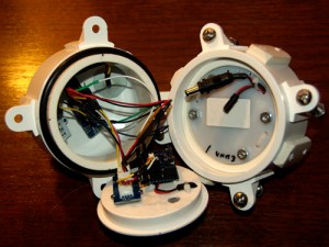
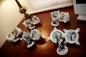
Modularize your designs:   Breadboards were never very practical for me because most of my projects get bashed around, and are supposed to run while the whole thing is in motion. But even after the prototype stage my sensors are not usually soldered directly to the data loggers. Yes, it’s a pain constantly making custom all those custom interconnect cables, especially since I color code everything – I2C bus, interrupt lines, …everything. And once you get an early prototype working, immediately build another one, and do all of your tests, etc., on the second unit, with the first working unit just sitting on the shelf.  Then if something stops working, you can use process of elimination with the known good modules to isolate the cause of the problem quickly. Often this technique helps me identify that the problem is actually in the software, and not with the hardware at all.  But I am still wading my way through the wonderful world of crimp connectors for ones that will prove robust enough for fieldwork. (note: I’ve adopted Deans Micro Plugs for my current builds…)

Coding:

Hit the verify button often, even when you make “simple” changes:  Don’t wait till you have been working for half an hour because humans can only remember 7±3 things (for this human, even less than that…)  You will be backtracking allot and error messages in the AVRc programming environment are usually about as helpful as a baby crying. You know something is wrong, but often you cant figure out what the problem is from the feedback it give you.  Something as simple as: “Hey man,  you left out a semicolon at the end of line 17” can be reported with anything from a one line “Expected X before Y” error to twenty (or more…) lines of cryptic compiler faults. Sometimes Google is your only friend when this happens.

The utility of a piece of code is directly proportional to how dangerous it is to use: For example: Global #define statements are tricky…especially when you are using libraries, because you never know when you have tried to “re-define” something hidden in one of those libraries. Interrupt handling is another example of something tremendously useful, and really easy to screw up when you have more than one sensor generating interrupts in the same piece of code, at the same time.

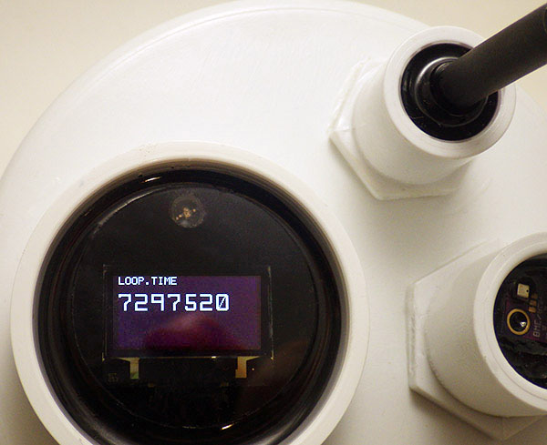
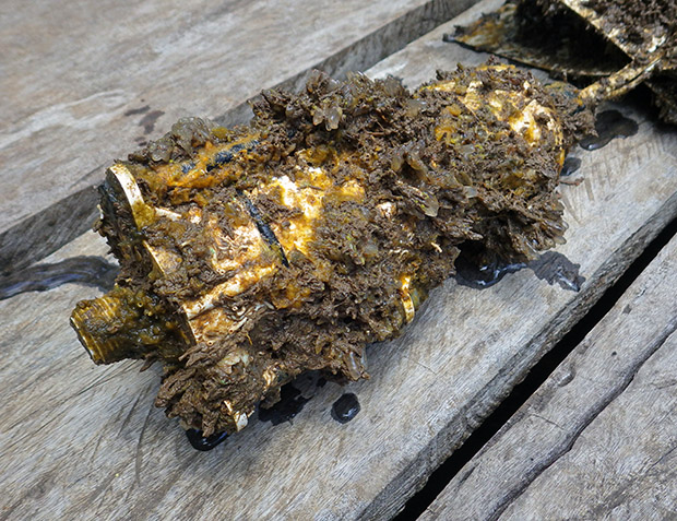
Software faults almost always show a repeating pattern of behavior: At least that’s been my experience so far. Bad wiring, or some other issue with the physical build, (like a v. regulator thermaling out…) hangs the system in a way that is much more unpredictable.  Of course, finding those patterns is a heck of a lot easier when your project is a data logger in the first place…

Physically putting “stuff” together:

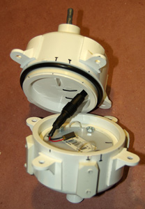
Third time’s a charm:  If your alpha works at all; that’s a great success. The holes will be in the wrong place, you will use too much epoxy, and it will be a clunky octopus of dodgy wiring. But even if it only runs for a single day, it has done the job of showing if the idea will work. (and they make such stylish book-ends…right?) The second build lets you sort out the right physical locations for all the components, and eliminates that hour of laborious hand-sanding that you really did not need to do.  This is also the model that lets you work out most of the software bugs, because it is usually much easier to open & close without breaking fragile jumpers all the time.  But for me at least,  it’s the third build that usually comes together in a way that feels right.

This type of bench vise is worth finding. I picked this used one up for $10, and it has been fantastic for holding parts together while epoxies cure & solvents weld PVC parts.

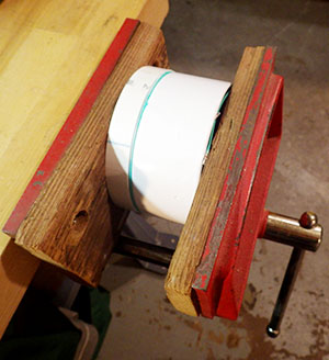
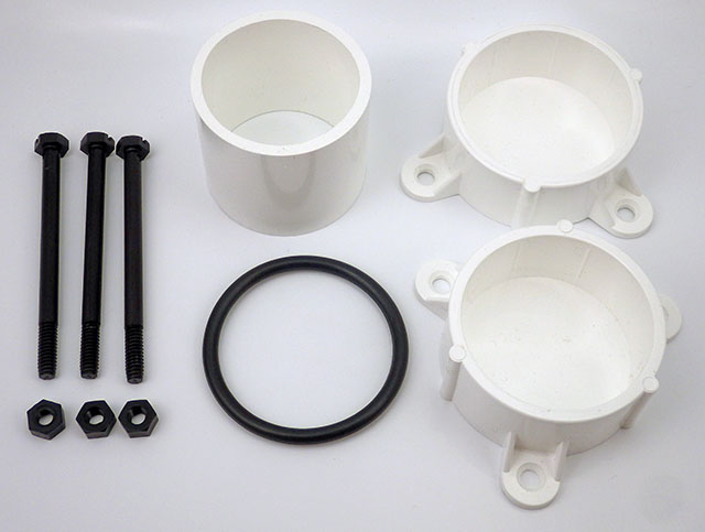
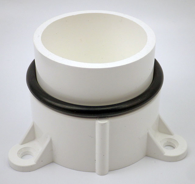
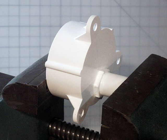
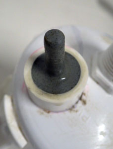
This type of bench vise is handy. I picked this one up for $10, at a garage sale and it has been fantastic for holding parts together while epoxies cure & solvents weld.

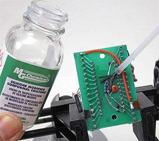
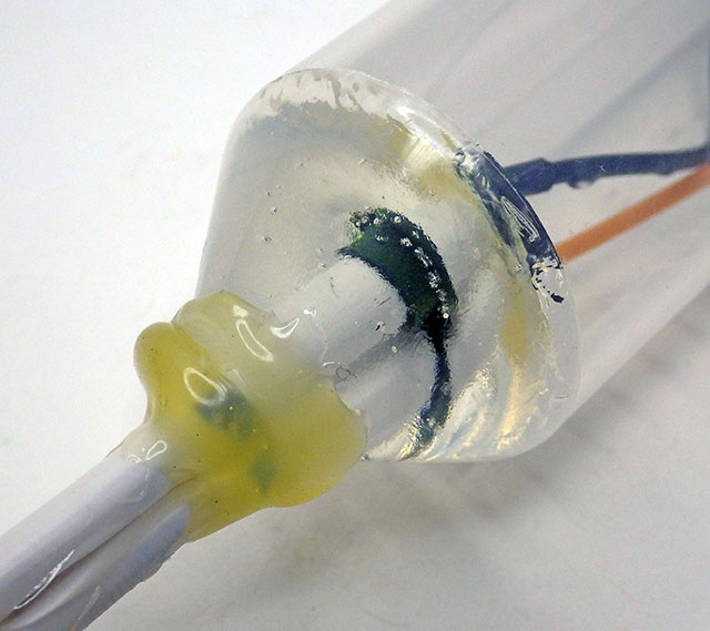
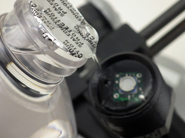
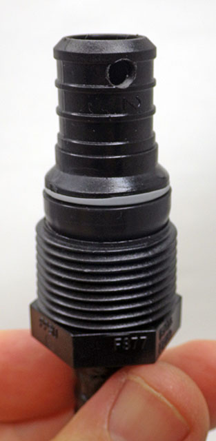
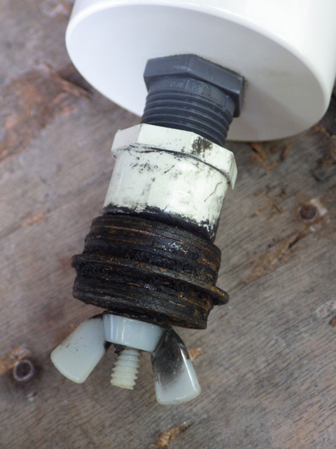
Adhesives & epoxies can be one of the most expensive components in your physical build:  (I wasn’t expecting this one) I go through a fair bit of Loctite E30-CL  (or E00CL for better PVC bonding) for my hull pen-etrations, and I love the fine control of the applicator gun.  But the mixing nozzles alone are more than a buck each, and they are elegantly design to waste a large volume of that precious epoxy with every use, which then solidifies inside the nozzles turning them into expensive single use devices.  That irritated me enough to start experimenting, and it turns out that Goof-off  (mainly xylene, and 2-ethanol) cleans out those applicator nozzles relatively easily. (Acetone would also work) I usually buy my adhesives from Zoro Tools. (note: their product search function is terrible, I use Google Shopping to hunt for stuff on Zoro’s site)  There are plenty of cheap Loctite sellers on eBay, but many are hawking expired lots.  In a pinch, I fall back to good old JB weld, and I use PlasticWeld putty absolutely everywhere because it nicely adheres sensor boards to both PVC & ABS in a way that is strong, but still removable (sort of..) if you have to repair something. Be careful not to bridge contacts with your adhesives on really sensitive sensors.  Most of these epoxies do not conduct electricity, so I use JB weld to shore up weak jumpers on I2C lines all the time. I have had problems with some sensors not working after gluing, probably because the cured epoxy added capacitive effects to the circuits. I have also started experimenting with 3M’s VHB double sided tape (for low surface energy plastic & acrylic substrates) to see if that is easier to work with. (Note: after testing the VHB did not work as well on the pvc as the standard 5lb mounting tape)

(…and if paying an “arm and a leg” for your adhesives wasn’t bad enough, those cheerful, brightly colored labels hide some fairly dire warnings about skin contact literally causing cancer, or vapors so dangerous that use of the product anywhere other than a open field is guaranteed to give you brain damage & significantly harm your … uhhh … “reproductive capacity”. Don’t believe me? Get a 200x microscope and read that fine print for yourself… just make sure you do it some place far away from stoves, heaters, electric motors and all other sources of ignition…like soldering irons 🙂 )

The shop course that you only took in high school to boost your marks will finally start to come in handy:  Turns out that working with PVC is almost the same as working with wood, so I was surprised by how much time I spent scoping woodworking forums while figuring out how to cut weird angles and then re-assemble things.

BigIron

An angle grinder pulls the rust off of old school tools in short order.

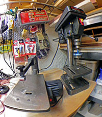
You can build anything with three pieces of  “iron”: A good soldering iron, a drill press, and a 13″ bench top scroll saw (which cuts PVC and trims circuit boards beautifully).  I have not regretted for one second putting down $100 for my little Haiko from Adafruit. (Wish I had bought the thing at the very start of this adventure.) But my other two irons are vintage Sears Craftsman models which cost next to nothing because when I bought them, they looked like flea-market clunkers from the days before plastic was invented. Cleaning them up was worth the effort because they weigh a ton, and are rock solid stable. In fact, these days I actually go out of my way to get old tools for my workshop. So if you see me one morning, at yet another garage sale, don’t be surprised if my hands are full of weird drill bits,  strange clamps, and other rusty lumps of metal that are even older than I am.

And last but not least:

I know everyone has their own taste, but I find that Pandora’s “Chillout” channel (in the Dance/Electronic genre section) just has a really good vibe for working on the bench. Spacey electronica wallpaper-music smoothly delivers the hyper focus I need to sustain a long soldering session, especially when the clock ticks on into the wee hours… .

Addendum 2014-07-29 

I have another one to add to this list but it stands outside of any category because it seems to apply equally. I call it the ‘Principal of Equivalent Annoyance’, and it’s just the observation that the dumb little things on a project take up at least as much time as the big important things. For example: when you connect allot of parts together, the physical behavior of your wires matters more than you’d expect because the difference between good insulation and stiff hard plastic puts quite a bit of pressure on the wires when you fit everything into the housing. Once and a while I am left with some excess lead wire from a sensor and when I open up the left over multicore cable I sometimes find a meter or so of the perfect wire.  Soft silicone insulation, 12 or more strands, no tinning… the stuff is fantastic to work with and is so flexible that it doesn’t stress the connections. Of course it never has any identification marks on it that might lead me to the source.  So I am slowly working my way through every brand of hook-up wire on the market, searching for this holy grail, and wasting more time on it than I even want to think about.  I suspect this is kind of thing happens on every project.

Addendum 2014-09-13

There are a few contenders so far in my ongoing search for “the perfect wire”: 

Adafruit sells 26AWG in multiple colors. This is my current favorite wire because they sell it in easy to handle packages (~0.95/2m) and they have the only grey & orange colored stuff I have found so far. It probably sounds silly to mention the packaging, but from other vendors like Hobby king, or eBay, you can expect to spend at least an hour untangling the spaghetti when your wire arrives. Their 30AWG is 0.70/2m, and is very handy for running jumpers across the surface of a breakout board.

Sparkfun sells their red & black silicone hook up wire at a good price, I just wish they had more colors.

Cal Test Electronics CT2956 Test Lead Wire:  (24awg $9 for 10 m, green, white) It is soft multi-strand bare copper and there is some variability in the stiffness as they seem to use different stranding depending on the color you order, but all of it is much more flexible than pvc insulated wire.  The insulation is nice and thin, so it crimps well into the standard 0.1″ connectors, and it is a bit stiffer than the Turnigy, so it will hold a bend you put in the wire.

Turnigy Soft Silicone Wire: (24awg $.60-$1 per meter, red, black, yellow blue) which is popular in the RC plane/Quadcoper crowd. Multi-strand “tinned” copper, with lots of colors. The very soft insulation is about twice the thickness of the Cal Test, but it still crimps nicely. (note: Hobby King does not let you mix warehouses on orders…)

There are two drawbacks to to using really soft silicone wire: You can not push the female crimp connector ends into the housings as you normally would with jumper wire. You have to dig in and pull the connector through the enclosure with tweezers.  The other issue is that because the silicone conducts heat so much faster than pvc, you will burn your fingers more often while soldering if you are not careful. In return,  you can stuff as much spaghetti as you want into a very tight housing without putting pressure your the solder joints in the process.  The wire stripper from Pololu, works well on both types of wire.

Addendum 2016-03-11

More eBay vendors for silicone jacket wire are appearing over time, and they are a great place to find a wider selection of colors like brown, purple, & pink. With module & jumper builds like mine, you need as many different colors as you can get your hands on. 

Addendum 2015-01-09 

I received a 10″ craftsman 21400 band saw for Christmas this year. And just like the night & day transition that occurred when I went from a crummy soldering iron to the lovely Hakko, my cuts have now become more accurate and virtually effortless.  No more risking my fingers trying to cut pipe on the table saw! And free-handing with a band saw accomplishes 90% of what I could do with the the jig saw as well.  If you can only afford to own one cutting machine, then I am now convinced it should be a bench-top band saw. Wish I had it from the beginning…

Addendum 2015-01-16

Looks like I am not the only one who is irritated by the waste generated by the Loctite 50ml nozzles. The folks over at RCuniverse confirm that acetone makes a good solvent for cleaning out the mixing tubes, and that its easier to do if you remove the white plastic mixing baffles first. They also mention that putting the nozzles in bags in the freezer will prevent the epoxy from setting, so I might try this trick to see if I can get the tubes to “self clean” by gravity. Looks like All-Spec is the cheapest source for the nozzles, but I keep finding “generic” mixing nozzles on eBay that claim they work with both 3M and Loctite adhesives. Haven’t tried them yet though.

Addendum 2015-02-02

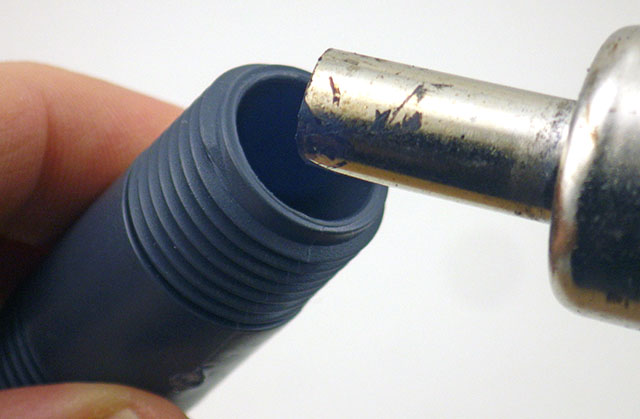
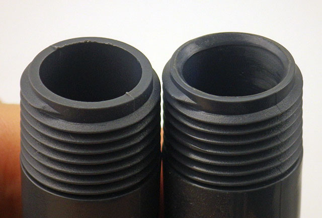
I bought some of the cheep MA5.4-17S 17 element mixing nozzles, and although the fit perfectly onto the 50ml dispenser, they were much shorter than the 15cm, 20 element, Loctite 98623 nozzles I usually use:

TopCheap_BottomLoctite

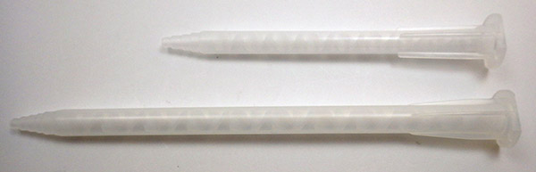
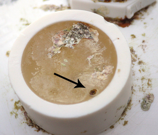
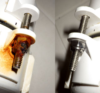
I thought this was a good thing, as I hate wasting all the epoxy that is left in the dispenser after every use and these smaller ones only retained 1.68ml in the barrel. I did some test pours under nearly identical conditions, and the smaller nozzles left a significant “swirly” pattern when the cured epoxy was examined close up a few days later:

Left side: Loctite Nozzle Right Side: Short Generic Nozzle

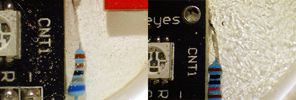
Left side: Loctite Nozzle                                                   Right Side: Short MA5.4-17s nozzle

I am interpreting this as a density gradient formed by inadequate mixing in the shorter nozzles. The epoxy has still set hard as a rock so I am not sure if this compromises the integrity too much. There are also listings for MA6.3-20S and MA6.3-21S nozzles, and I will try some of those next time.

(Note: the MA6.3’s worked great, as did the $10 applicator guns on eBay)

The new fleet of flow sensors is ready to sail!

Hi everyone. I wrote most of this entry on a plane today, as it was almost the first free time I’ve had “away from the workbench” since the initial proof of concept loggers were deployed last year. I have redesigned the Cave Pearl data loggers into a more modular platform that should be flexible enough for quick field repairs, while enabling future development with more sensors.  (I want at least CTD, and my wife has an infinte supply of other suggestions  🙂

The loggers are now assembled in four interchangeable components, which from top to bottom are:

1) Upper housing

It was too cold in the basement for the epoxies to set properly...

It was too cold in the basement for the epoxies to set

Lots of lessons have been learned here about sealing the hull penetrations thanks to the diy ROV crew. Sort lengths of 3/4 pipe form “wells” to protect the sensors, with JB Plastic Weld putty wrapped around the wires as they initially pass through from the inside of the housing. The putty sets on the roughened surface, pluging the hole and holding the sensors in position, but I found that the silicones I tested flex quite a bit after curing, so they are too easily “sheared” away from the pvc surface. As a result,  the current builds use JB weld around the DS18B20 thermal sensors, and Loctite E-30CL to for a transparent seal over the “heartbeat” LEDs which pip when the samples are taken. Experience has shown me that you must have some way of knowing your units are working happily (or if they are in an error state…) before you dive them into the cave.

2) Main electronics platform

The LED is an Octopus Brick because they had a good buckled connector, and the RTC is a cheap DS3231 module from eBay because I wanted the AT24C32 it had on board.

The LED is an Octopus Brick because they had a good buckled connector, and the RTC is a cheap DS3231 module from eBay because I wanted to use the AT24C32 eeprom it also had on board.

I am still quite happy with Tinyduino, as the package integrates the mcu, accelerometer, and now digital compass, with the smallest footprint and the least amount of extraneous wiring. I put riser pins on their new overhanging protoboard, and this jumps out to a grove I2C hub as a central interconnect system allowing me to interchange the logger platform with housings that will sport different sensors in future.  All of the electronic components have had a good bath of conformal coating this time around, so hopefully they will be a bit more robust. (I might try Rustoleums Neverwet next time)

3) Power supply

The gap between the two shells provides room for the interconnect, and some filtering caps, etc. if needed.

The gap between the two shells provides room for the interconnect, and some filtering caps, etc. if needed.

Physically it’s just two pvc knockout caps held together with four bolts & a 1cm “hold down ring” to keep it in place in the lower housing. Electronically there are two versions. The first is an unregulated supply uses two banks of 3 AA batteries, through Shottky diodes to prevent the banks from draining unequally. This supply will drop from 4.5 volts down to a lower cutoff of 2.8 volts before the system stops logging, so it needs fairly robust sensors. The second power supply uses three banks of 2 AA batteries (with three Shottky’s) feeding into an NCP1402 3.3 volt boost regulator which then powers the logger. Several of the sensors I want to use have a strict 1.8-3.3v input range, so they can not be used with an unregulated system. It will be interesting to see if the greater “draw-down” enabled by a boost regulator compensates for the power it wastes (here about 25%). This deployment will hopefully be some months long, so I will find out how the regulated VS unregulated systems actually perform.

4) Lower housing & external weight system

This series needs about 100-150 grams of ballast mass to be neutral.

This series needs about 100-150 grams of ballast mass to be neutral.

The buoyancy troubles we had on the initial deployment showed me that I needed some form of external system to compensate for changes in battery mass, cable buoyancy, salinity, etc. So I have a simple solution using a bolt through a threaded end cap which holds a number of washers as ballast. All stainless steel, but I am curious to see how long they actually last in the near marine environment. The buoyancy mass will be spit evenly on the top & bottom of the units to prevent rotational torques which which would affect the angle readings.

The battery run down tests are still looking very good for one year + deployments!

The battery run down tests are still looking very good for one year + deployments!

So this is the new fleet: Four pendulum units and one high resolution temperature &  pressure sensor that will remain stationary.  Hopefully they will all be underwater logging in a few days. Looking back at the build journal, I should add that there has also been a fair bit of coding, but I will post details on all that later, after I have integrated support for the HMC5883L digital compass & MS5803 pressure sensors into the main logger script.

BUT before we deploy these new units,  we need to go and retrieve Beta’s 1&2 which we left in a cave last December.  My fingers are crossed that they have survived these last few months under water…

<—Click here to continue reading—>

Addendum 2015-01-07

For the DIYers out there, I should mention that this housing style proved quite robust through several deployments in 2014, and probably could go to substantial depth due to the thickness of the 3″ end caps.  But in early 2015 I came up with a new design built with Formufit table caps, which is much easier to assemble provided you can squeeze your electronics package into 2″ pipe.

Field Report 2013-12-06: The moment of truth…

A couple of days into the UNAM research, there was break in the schedule, so we had the opportunity to go back and retrieve the units. When we arrived at the installation site, everything looked exactly as we had left it, with no apparent leaks or other damage to the housings.  But on closer inspection, we did observe that the two units were not exactly behaving the same way:

After catching a little more video, we spent a few minutes collecting the sensors. A short while later we finished the dive, and soon I was carefully cradling the loggers on my lap as we drove back to the CEA dorms. Once there I made sure that the units were absolutely dry before I opened them up to retrieve the SD cards.  I could see from the size of the files that both units ran smoothly, and had logged data. But what had they recorded?

Once the files were on the laptop, my wife, an Excel virtuoso, took over.  Within moments we were starting to see bumpy graphs displaying the three axes of the accelerometer.
A little more adjusting, a few labels, and we were looking at this:

3 days of raw data from the very first deployment.

Raw data from the first deployment: x,y&z axes, but with different orientations relative to flow direction.

“Is that good?” I asked. I could barely contain my excitement.

“Yes,” she replied with a big smile, ” for uncalibrated, first run data, this is pretty good.”

“Why two peaks per day?” I thought there might be a problem with the sensors.

“Actually.” she added, “That’s normal.  This area has semi-diurnal tides, and the velocity curves are often asymmetrical like that.”

“Yaayyyy!” I whooped, “We did it!” And I think I even started dancing.  Months of noodling around in the basement, and combing through forums, had just been transformed from “another one of Ed’s crazy projects…” into two real working prototypes!

It was well into the evening by this point, so we headed out for a late dinner, and a couple of celebratory ‘cervezas’.  We discussed where we might put them next, so that we could learn more about the quality of the data they were generating. I wondered about how we might calibrate them against some commercial units, and Trish said that even without ‘absolute’ velocity numbers, the information would still be useful to her research. But for me,  the real bottom line was the moment when she asked:

“How soon can you make me some more of these things?”

<—Click here to continue reading—>