

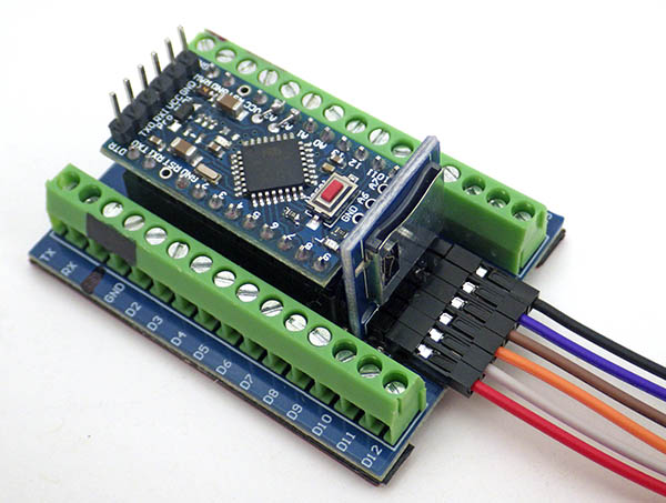
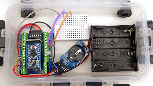
2020 update to the Cave Pearl Classroom logger. This is a combination of inexpensive pre-made modules from the open-source Arduino ecosystem, and can usually be assembled by beginners in 1-2 hours.
(Latest Update: Mar 9, 2022)
Covid has thrown a spanner into the works for hands-on learning because even if you have the space to run a ‘socially distanced’ course, your students could still be sent home at any time. With that in mind, we’ve divided the build tutorial from 2019 into separate stages that make it easier to restructure the labs:
1) Component prep: requires the equipment you normally have access to in the lab like soldering irons, heat guns, drills, etc.
2) Logger assembly: can be done remotely with scissors, wire strippers & a screwdriver. All connections are made by Dupont connectors or by clamping wires under screw terminals.
The complete tutorial can be run in person or if students are ‘distance learning’, the instructor can do the soldering (~15-20 minutes per set) and send out kits for the overall assembly. Even that will be challenging through a zoom window, so you might want to add USB isolators to protect tethered student laptops from accidental shorts. One big challenge of running a course remotely is the extra time to test all the parts before sending them out. A ‘breadboard logger’ like the one shown later in this post lets you do that testing quickly. Another challenge is that other USB devices can push the bus too fast for the slow serial UARTS, causing them to drop off the system due to timing conflicts. (this is more common on Apple computers).
During ‘normal’ runs if a student gets a bad component, or accidentally zaps something in one of the labs, then it simply triggers a brief process-of-elimination lesson while they swap in replacements from the storage cabinet until things are working. But remote students won’t have that option unless you send two of every part – which might be viable approach considering how cheap these components are:

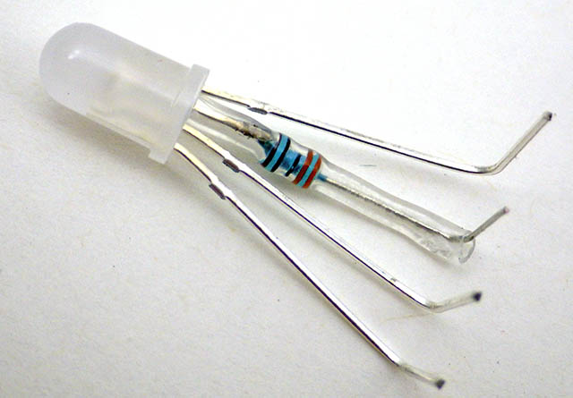
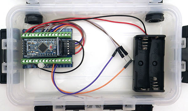
This is a variation of the logger described in our 2018 paper but we’ve removed the regulator/ voltage divider and added screw terminals + breadboards for faster sensor connections during labs. Bridging the I2C bus over the A2 & A3 pins leaves only two analog inputs on the screw-terminals. However for ~$1 you can add a 15-bit ADS1115 which provides differential analog readings using a fixed internal reference. So it’s unaffected by changes in battery voltage.
The main components:

(NOTE: complete parts list with supplier links can be found at the end of this post) You don’t need the cable glands if you are using sensors that will work inside the housing (light, temp, acceleration, magnetometers, GPS, etc.) Don’t put holes in your housing unless you are sure you need them.

Two FT232 adapters (in red) & a CP2102 UART module (blk) with a pin order that matches the ProMini headers:[DTR-RX-TX-3v3-CTS-GND]
You will need a UART adapter module to program your logger – This must support 3.3v output & is easier to use if the pin order matches the ProMini connections. UART modules available with the FT232, CP2102, & CH340 chips will all work if the chip maker supplies drivers for your operating system.
The Arduino IDE will NOT be able to communicate with your logger unless the driver for your UART module is installed on your Windows or MAC operating system. We use FTDI basic UART modules & you can download the driver at the FTDI website. There’s a basic installation guide at Adafruit , a more detailed one at Sparkfun, and PDF guides from FTDI.UART chips can only supply ~50mA so if your sensors need more current you might run out of power causing a restart of the ProMini. (A somewhat common problem when testing high-drain GPS modules or wireless transmitters)
(NOTE: I have connected ProMini’s to UART modules the wrong way round many, many, times, and none have been harmed by the temporary reversal. Also note that FAKE FTDI chips are a common problem with cheap eBay vendors, so it might be safer to buy a SiLabs CP2102, or CH340 UART from those sources. If you are using the ‘cheap ones’ it’s a good idea to include UART modules from two different manufacturers in the student kits to deal with the inevitable driver compatibility issues.)
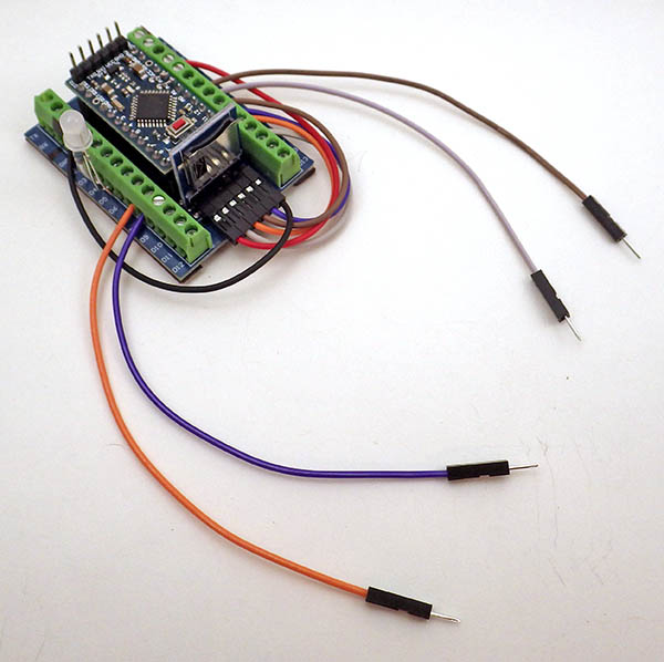
Component Prep. Part 1: Pro Mini ( 3.3v 8Mhz ) (click any image to enlarge)
 With a known good Promini: Remove the power LED [in red square]. SPI bus clock pulses will flash the pin 13 LED – so leaving the pin13 LED connected will show you when data is being saved to the SD card. |
 Carefully remove the voltage regulator from the two leg side with snips. System voltage will vary over time, but the logging code we’ve provided on gitHub records the rail without a voltage divider by comparing it to the 328p’s internal bandgap. Lithium AA’s also provide a very flat discharge curve. |
|
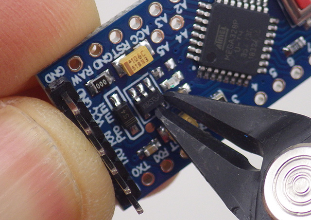
 Add header pins to the sides but DO NOT SOLDER THE RESET pin HEADERS – we will be using those screw terminals as power rails. |
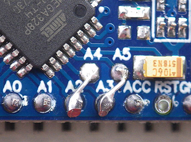
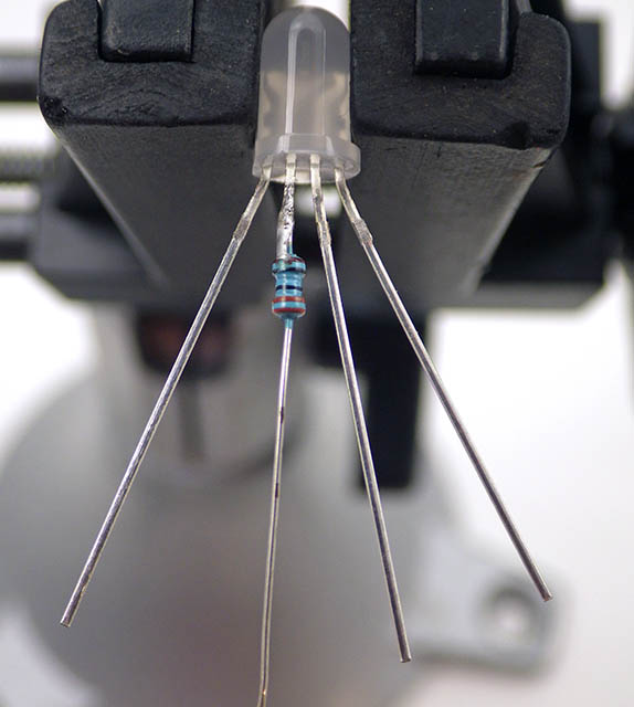
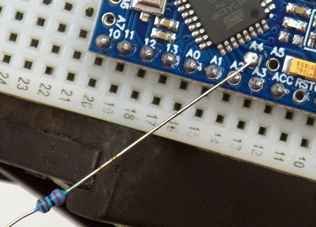 Bridge the two I2C bus connections with the wire leg of a resistor. Connect A4->A2 & A5->A3. |
 Adding: DIDR0 = 0x0F; in Setup disables digital I/O on pins A0-A3 so they can’t interfere with I2C bus. |

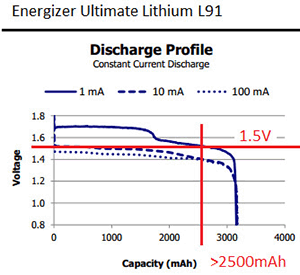
Lithium AA batteries are preferred when running a 2-cell unregulated system because the slope of an alkaline discharge curve will reach the ProMini’s 2.7v brown-out with >50% of the battery capacity unused. (note that SD cards are safe down to ~1.8v) While the voltage of a newLithium AA is usually 1.8v/cell, that upper plateau usually settles at ~1.79 v/cell within an hour or two of starting the logger. That briefly dips to 1.6v/cell during >100mA SD card save events at room temp. At temps near 5°C (in my refrigerator) the SD write battery-droop reached about 1.5 v/cell while on the upper plateau. Lithium cells only deliver ~50% of their rated capacity at temps below freezing, but that’s still an improvement. And alkaline batteries leak quite often – even when they are not fully discharged. To date, leaking batteries have been the most common reason for data loss on our project.
The MIC5205 regulator is not efficient at low currents, so removing it reduces your sleep current by ~50%. However that modification also forces you to deal with a rail voltage that changes over time. Thermal rise from 15 to 45°C will raise your rail voltage by about 100 millivolts on lithium cells that have been in service for a few months. (~ 5mv /°C) If your sensor circuit is a voltage divider that is being powered by the same voltage the ADC is using as a reference then the ADC readings are unaffected by this. However you will need to compensate for this in your calculations if your analog sensor circuits are not ratio-metric. Battery thermal mass will cause hysteresis unless you read your reference resistors under the same conditions. Regulated ProMini’s usually see the rail vary by ~10-20 millivolts over a similar range of temperatures however it’s worth noting the reg/cap combinations on cheap eBay modules can be subject to other problems such as noise; which can be even more problematic wrt the quality of your data. Most chip-based I2C sensor modules carry their own regulators (usually a 662k LDO) and use internal bandgap reference voltages so they are unaffected by the changing rail.
So making students deal with deal with power supply variation right from the start will save them from making more serious mistakes later because every component in your logger is a temperature sensor.
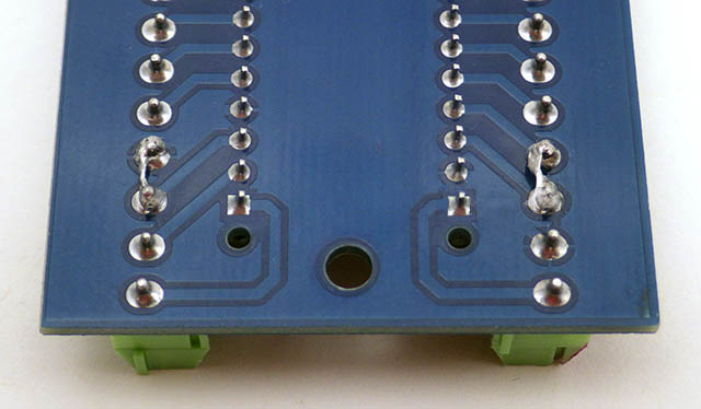
Component Prep. Part 2: Screw-Terminal Board & SD adapter
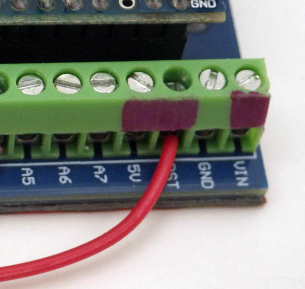
 At the UART end of the board: Use a tinned resistor leg to repurpose the RESET terminals: Join RST & GND pins on the digital side and link the pins labeled RST, 5v and Vin for the positive rail. (include Vin only if the reg. has been removed! ) |
 Label the screw terminal blocks that were connected under the shield with red & black markers to indicate the power rail connections. We have no reverse voltage protection – so insert AA’s w the correct polarity or the polarized Tantalum caps will burst. |
 Gently rock the Pro Mini back to front (holding the two short sides) until the pins are fully inserted. Some ST shields have slightly misaligned headers so this insertion can be tricky. |
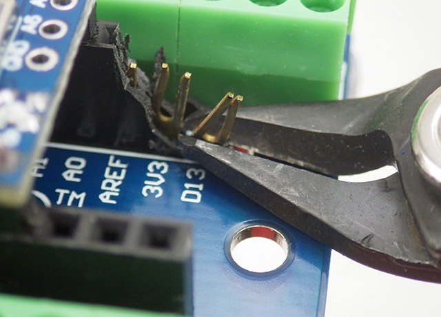 Remove the last three ‘unused’ female headers to make room for the SD adapter which fits perfectly into that pocket |
 NOTE: The SDfat library uses SPI mode 0 which sets the SCLK line low when sleeping causing a 0.33mA drain through the 10k SCLK pullup on the module. |
 Remove the bottom 3 resistors from the SD adapter – leave the top resistor near the C1 label in place! |

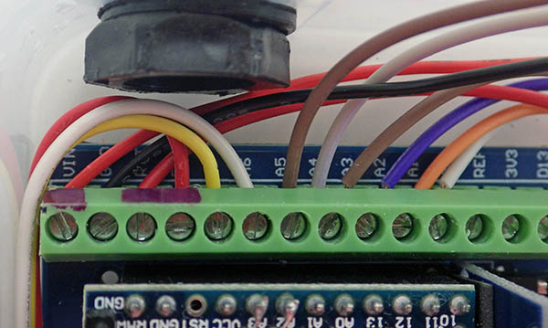
NOTE: The Screw Terminal board we use in this build was designed for the 5v Arduino NANO, so the shield labels don’t match the Pro Mini pins on the ‘analog’ side. (the digital side does match) To avoid confusion may want to tape over those incorrect labels and hand write new labels to match the pattern above. Wire connections in this tutorial will be specified by ProMini pins: D10-13 are used for the SD card, A4/A2 is the I2C Data line, and A5/A3 is the I2C clock line.
Technically speaking, bridging the I2C bus (A4=data & A5=clock) over top of A2 & A3 subjects those lines to more capacitance and pin leakage. (regardless of whether that channel is selected as input for the ADC p257). However in practice, the 4K7 pull-up resistors on the RTC module handle that OK at the 100 kHz default bus speed.
Adding DIDR0 = 0x0F;
in setup disables digital I/O on pins A0-A3 to prevent interference with A0/1 ADC readings and the I2C bus on A2/3. If you want to disable only the digital IO on only A2 & A3 add
bitSet (DIDR0, ADC2D);
bitSet (DIDR0, ADC3D);
to setup{}.
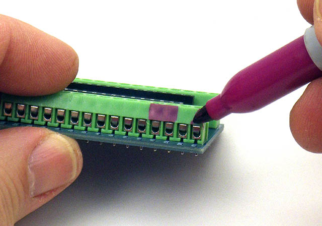
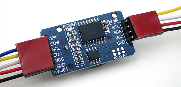
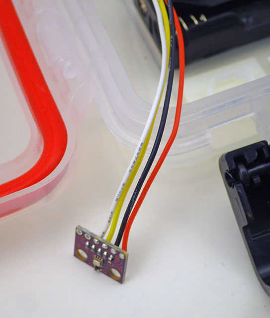
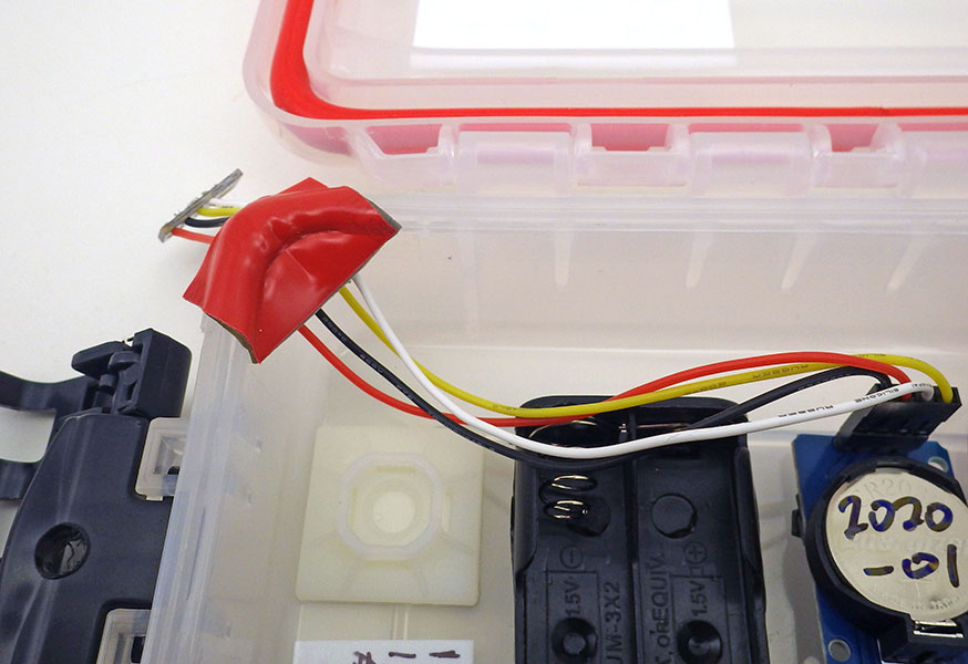
Component Prep. Part 3: RTC Module, Indicator LED & Plano 3440 Housing
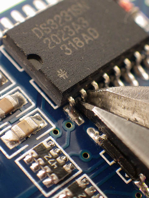
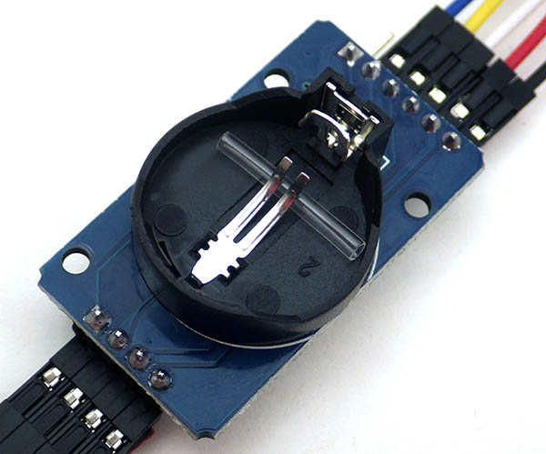
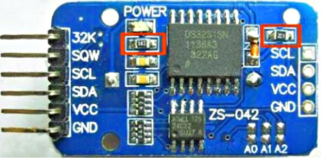 Remove two SMD resistors from the RTC board with the tip of your soldering iron. Note that this module includes 4k7 pullup resistors on SQW, SCL & SDA – leave those in place! |
 Optional! Cutting the Vcc leg lowers sleep current by 0.1mA but no I2C bus coms until coincell is installed. |
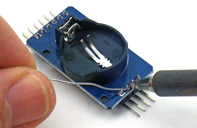 Add 90 degree header pins to the I2C cascade port. Note: Cutting the VCC leg also requires you to ‘enable alarms from the backup battery’ with a registry setting. |
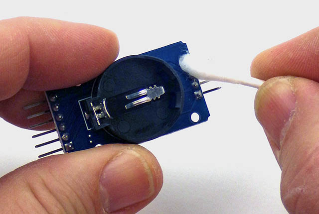 Clean flux residue from both the main & cascade header pins with 90% isopropyl alcohol |
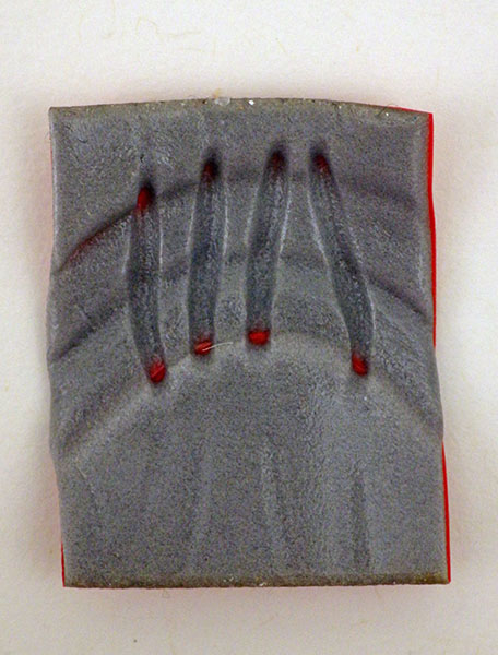
 Use a coin cell to determine the GND leg of a diffused common cathode RGB LED |
 Solder a 1-2k ohm limit resistor on the common GND. The precise value is not critical. |
 Add heat shrink, bend & trim the pins for connection to the screw terminal board. Pre-made 5050 modules also work but are not as good in light sensing mode. |
 Add holes in the rear struts of the Plano 3440 Stowaway housing to provide logger tie-down points later. |
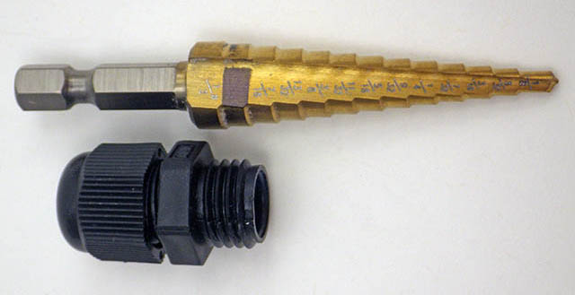 Stepped drill bits make clean holes in plastic housings for different thread diameters. We use glands with waterproof DS18b20 sensors on 1m cables. |
 Centered holes are ‘slightly’ closer the bottom of the box to allow the gland to rotate without hitting the rim. Inner nuts must also be able to rotate for tightening. |
 Rubber washers are added to both the inside AND the outside surfaces. PG7 sized washers also fit the M12 cable glands we use. |
 A 3440 Plano Box configured for two external sensors with nylon M12 cable glands for 3-6mm cables. After threading sensor cables I often seal the outside of the glands with a layer of silicone goop or nail polish. |
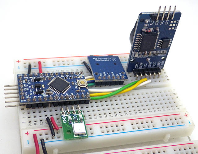
As with the ProMini, it’s worth testing the RTC modules & SD adapters before logger assembly. I keep a breadboard version of the logger handy so I can test several at a time. If the RTC temp register reads too high I throw them out because the clock time is corrected based on those internal readings. You could also set the clock at this point if the coin-cell is already in place. Note the 5050 LED module on the breadboard shown above could replace the 5mm LED in this tutorial.
Forcing the RTC to run from the backup coin cell reduces sleep current by ~0.1mA, bringing a typical “no-reg & noRTCvcc” build to ~0.15 mA between readings. (with most of that for the sleeping SD card) As a rough estimate, Lithium AA’s provide ~7 million milliamp-seconds of power, and your logger will burn ~12,960 mAs/day at 0.15mA. So ‘in theory’ you could approach a year before you fall off the ‘upper plateau’. The clock will reset to Jan 1st, 2000 if you disconnect the RTC’s coin cell with a hard bump, but a couple of drops of hot glue should prevent this. If a reset does occur the time stamps will be wrong, but the logger will continue running the next day once the clock rolls around to the previous hour/minute alarm that was set. A CR2032 can power the RTC for about four years but if you cut the vcc leg you must set bit six of the DS3231_CONTROL_REG to 1 to enable alarms or the logger will not be able to wake up. (NOTE: our logger code does this by at startup with the enableRTCAlarmsonBackupBattery function, which only has to run once – the RTC remembers the setting after that)

The soldered components ready for assembly.
Cutting the Vcc leg on the RTC is optional: if you leave the RTC power leg attached you’ll see typical logger sleep sleep currents in the 0.25 mA range, which should still give at least 4 months of operation before you trigger a low voltage shutdown. I’m being conservative here because runtime also depends on sensors and other additions you make to the base configuration.
See our RTC page for more detailed information on this DS3231 module.
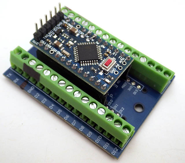
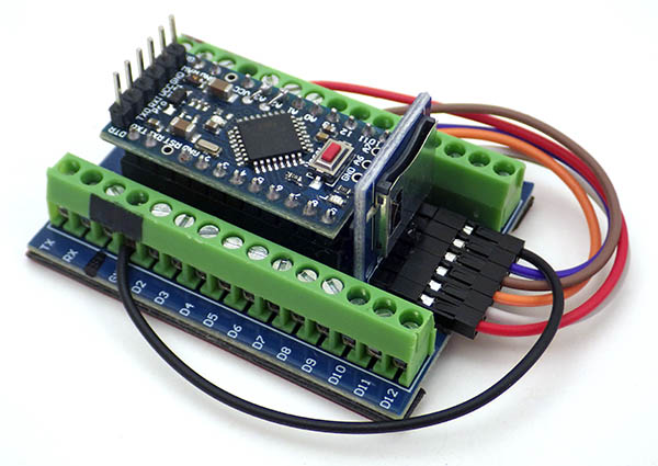
Assembly Part 1: The Screw-Terminal Stack
Part 1: This stack is the ‘core’ of your data logger.
It is very easy to get a couple of wires switched around at this stage so work through these instructions slowly & carefully. Connect the Dupont jumpers to the SD module so that the metal retainer clips are facing upwards after the logger is assembled. That way you can diagnose connection issues with the tip of a meter probe on the exposed metal and, if necessary, pull out & replace a single bad wire without taking everything apart. The extra wires you trim from the SD module are re-used.
 Add 2-3 layers of double sided foam tape to the sides & center of the screw terminal shield. The tape needs to extend farther the height of the solder points. |
 Add single wires from the 20cm M-F Dupont cable to the SD adapter. 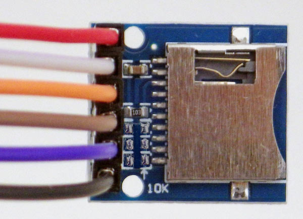 The ‘metal tabs’ of the Dupont ends are facing the large metal shield over the SD card. |
 A layer of double sided foam tape secures the connectors & extends over the solder points.
|
||||||
 Tape the SD adapter into place on the area that’s been cleared at the back of the screw terminal board. |
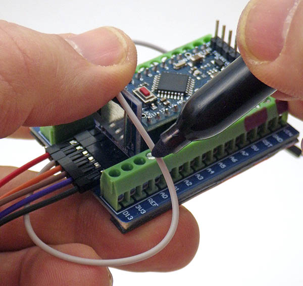 Bend the jumper wires into place, mark the length & trim the original 20cm wires so that the final insulation length is 9cm or less. |
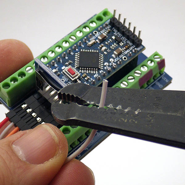 Score the wire insulation about 1.5cm back from the wire end but do not remove the insulation. |
||||||
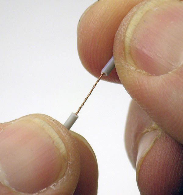 Gently ‘pull & twist’ the scored insulation away from the wire to wind the thin strands together. |
 ‘Fold-back’ about half of the stripped wire to provide more copper surface for the screw terminals to bite on to. |
 SD Connection pattern: Grey (CS) to ProMini D10, Orange (MOSI) -> pm D11, Purple (MISO) ->pm D12, Brown (CLK) -> pm D13 (NOTE the shield labels say A0-A3 which do not match the D10-13 pattern of the Pro Mini pins) |
||||||
 Bring the red SD wire over to the re-purposed RST power connection |
 and the black wire to GND on the digital side. At this point you could test the connections by inserting an SD card & running the CardInfo utility. |
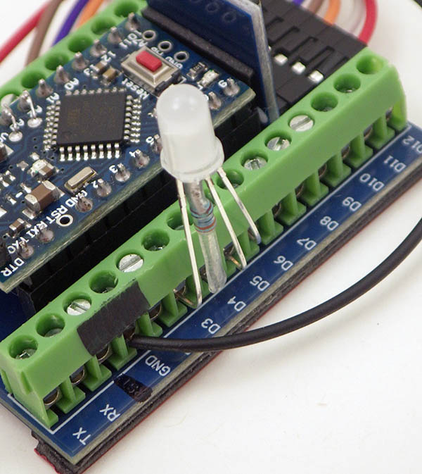 Connect the legs of the indicator LED at: D3=red, D4=GND, D5=green, D6=blue |
||||||
 Use the male ends of the wires you trimmed from the SD module to break out pin connections: Grey to A0, Brown to A1, Orange to D7, Purple to D8. |
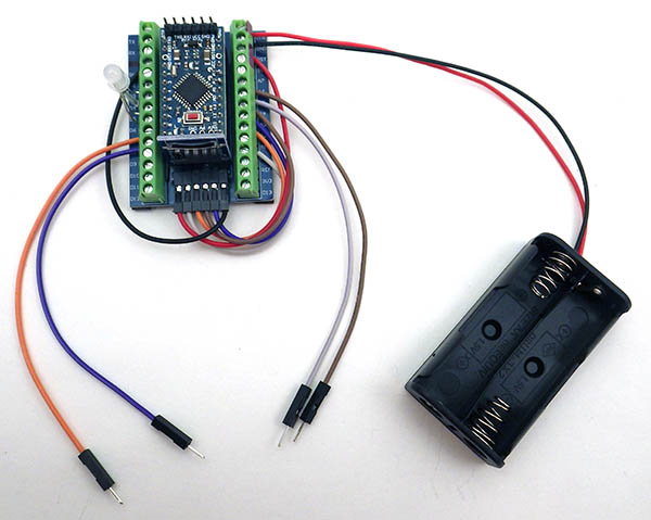
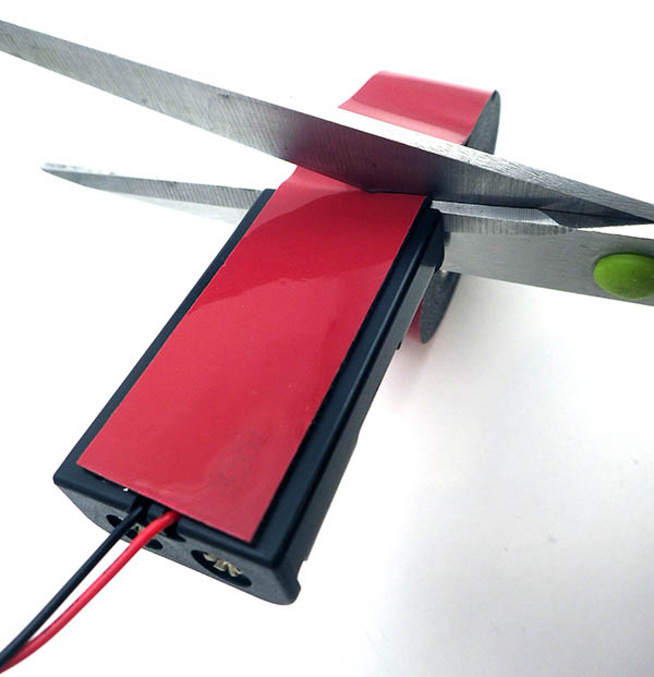 Add a layer of heavy duty (30Lb) double sided mounting tape to the back of the 2xAA battery holder. The battery holder wires need to be approx. 6inches/15cm long. |
Attach the battery holder wires to RED>Vin & black>GND. The breakout wires from A0/1 & D7/8 should be about 12cm long to comfortably reach the breadboard area. |

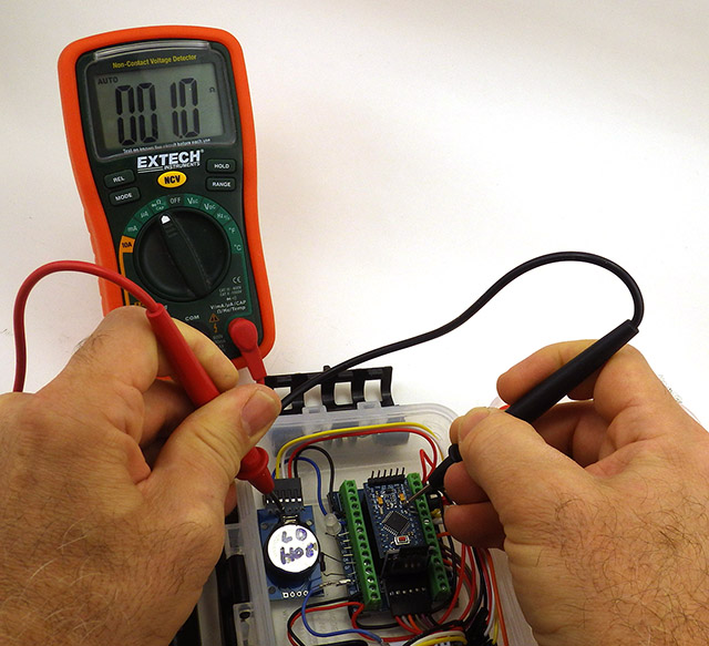
Checking continuity to the top of the ProMini confirms the header pins & solder connections under the terminal board are good.
Take a moment to check the continuity of the SD module wires. With one probe on the Dupont metal & the other on top of the corresponding ProMini pin – you should read ~1 ohm or less for each connection path. Occasionally you get a bad crimp-end on those multi-wire Dupont ribbons, and it’s easier to replace a bad wire at this stage than it is after the parts are in the housing.
Note: We’ve used the hardware interrupt port at D3 for the red LED channel, but if you have sensors that need that simply shift the LED over by one. Any digital I/O pins can be used for the LED, but 3,5 & 6 have PWM outputs which lets you do multi-color fades with analogWrite()
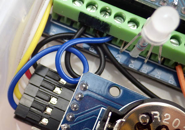
Assembly Part 2: Add RTC Module Jumper Wires
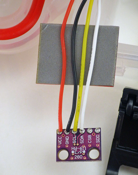
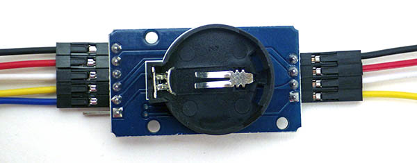 Attach Dupont jumper wires to the RTC module using White=I2C Data, Yellow = I2C Clock. Blue is the SQW alarm output line. Nothing is attached to the 32k output pin (cutting the Vcc leg disables 32k output) |
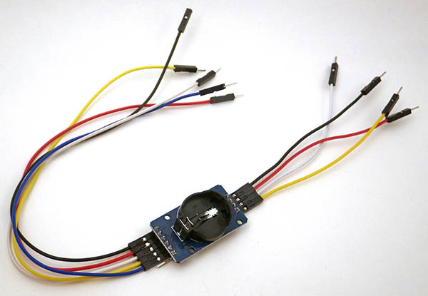 Use 20cm M-F jumpers on the 6-pin side of the RTC module and shorter 10cm M-F wires on the smaller 4-pin cascade port. |
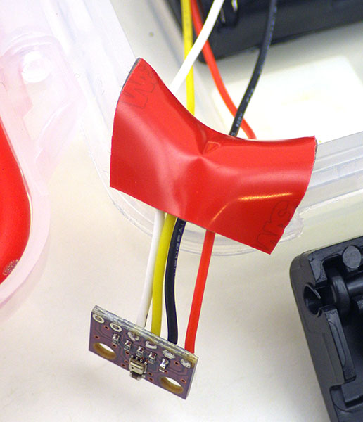
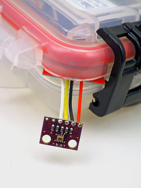
 Add a layer of double sided tape to secure the jumper shrouds, and provide housing attachment points for the module. |
 Add as small piece of 1/16″ heat shrink tubing to reinforce the contact spring. This reduces the chance that the connection will be bumped loose if the logger is dropped. |
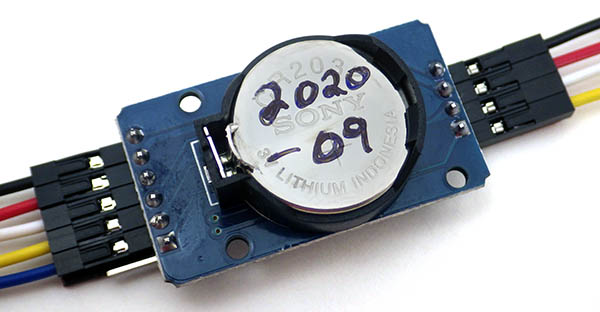 Write the installation date on the coin cell with a marker. A new coin cell should power the RTC for about 4 years. To avoid accidentally disconnecting the coin cell battery after the logger is assembled -> |
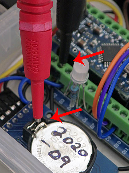 Always check the backup voltage by placing the positive probe tip between the spring plates rather than on the surface of the cell. |
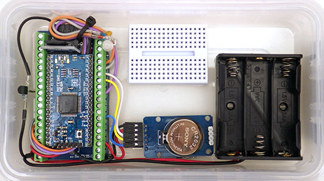
Assembly Part 3: Connect modules inside the housing:

Part 3: This is what you are aiming for. (click any images in the table below to enlarge them)
The final assembly stage can be a bit tricky – sometimes the metal contact flaps under the green screw terminals are ‘sticky’ so take some time to loosen the screws and poke with the sharp end of your tweezers to make sure you can insert the bus wires from the RTC. It’s helpful to mark the wire lengths with a pen before cutting or stripping the RTC connections. When in doubt leave them a bit long. With screw terminals you always have the option of shortening those wire later on.
 Attach the screw terminal stack onto the upper left corner of the housing, and the 2xAA battery holder in the lower right corner. These parts sb as far from each other as possible. |
 Add the first mini breadboard against the back so that it’s rear right edge aligns with the second rear support strut on the housing. Connect the long stack jumpers to that bboard to keep them out of the way. |
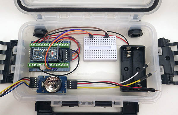 Tape the RTC module into the lower left side of the housing, The blue board should be up against the front edge of the housing so that you can easily access the nearby screw terminals. |
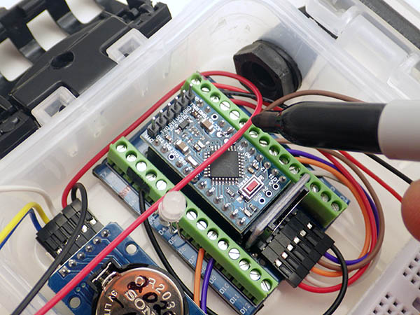 Measure, mark and trim: Red=3.3v, Yellow=>A3/A5 I2C clock, & White=>A2/A4 I2C data with enough wire to twist & fold the stripped ends under the terminals (~10cm of insulation length) |
 RTC module power & I2C bus connections: All ports on the analog side of the Pro Mini / Shield combination are occupied with a wire connection. |
 Connect the black wire to the re-purposed RST=GND, and the blue alarm wire to D2, leaving some extra wire length in a loop for strain relief. (5-6cm of insulation length) |
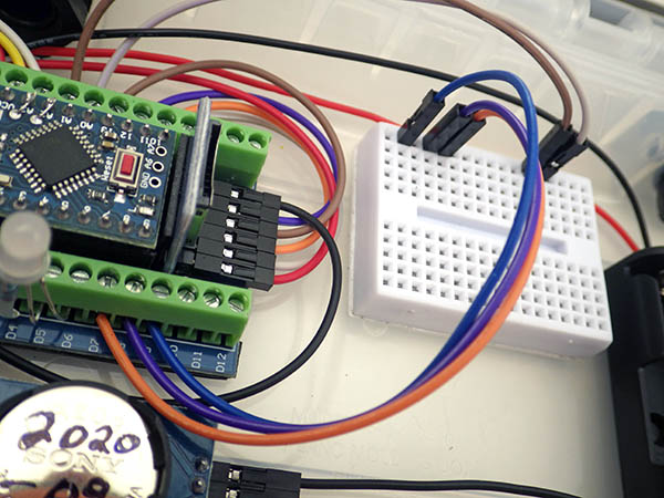 Use the other side of the trimmed blue jumper wire to extend the D9 connection over to the breadboard. You want enough wire length that the pins reach back-most row on the breadboard. |
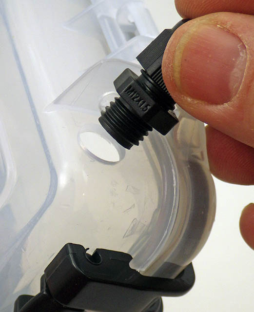
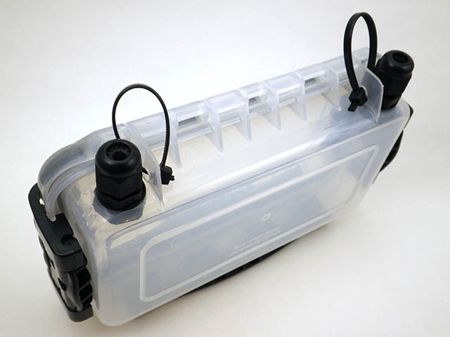
 Attach a cable mount to the back of the housing, as close to the bottom of the box as possible so that it does not interfere with closing the housing lid. You can trim those plastic mounts with scissors to make them thinner. |
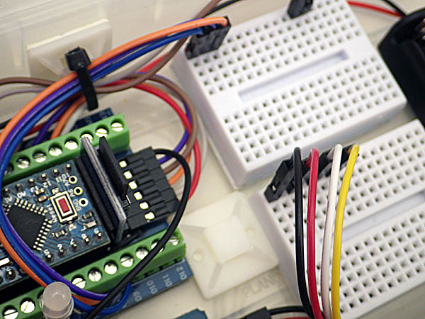 ‘Loosely’ tie the long wires to the rear mount. Add another cable mount near the center and attach the 2nd b-board leaving equal side of the 2nd board. |
Every year at least one student gets confused about the orientation of the connections inside the breadboard and connects all the jumper wires together in the same row – including the red and black power wires. The resulting short circuit usually kills either the Pro Mini, the UART module, and/or possibly even the USB port on the computer it’s connected to:
 |
 Each 5-hole row on the top of the breadboard is connected by a metal rail of spring contacts. |
Also note that the internal connectors do not cross the ‘gutter’ depression in the middle, so each side of the breadboard board has its own separate set of connections.
Your Logger is now ready for testing!

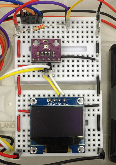
A typical I2C sensor configuration with: BMP280 pressure, BH1750 lux & 0.96″ I2C OLED display – connected by short jumper wires made with a crimping tool. The combination shown above averages ~10mA with screen & cpu running, and a sleep current of 0.147 mA with a 1Gb Sandisk SD card. Without the SD, the sleep current on this unit was 37µA; with the sensor modules needing 2-3µA each & the sleeping 0.96″ OLED drawing ~7µA. A 25µA sleep current from the ProMini clone hints that the MCU might be fake but with a AA power supply it doesn’t really matter. Anything up to 250uA sleep current for a student build with an SD card connected should be considered good. Watch out for SD cards that don’t go to sleep properly as they can draw up to 30-50mA all the time.
(Note: Most of the time the tests listed below go well, however if you run into trouble at any point read through the steps suggested for Diagnosing Connection Problems at the end of this page.)
1. If you have not already done so, Install the UART driver. The IDE will NOT be able to communicate with your logger unless the driver for your UART module is installed on your operating system.
2. Install the Arduino IDE into whatever default directory it wants – we’ve had several issues where students tried to install the IDE into some other custom sub-directory, and then code wouldn’t verify without errors because the IDE could not find the libraries. The programming environment is written in Java, and the IDE installer comes with its own bundled Java runtime so there should be no need for an extra Java installation. However we have seen machines in the past which would not compile known-good code until Java was updated on those machines; but this problem is rare.
If you have not already done so, there are three things you need to set under the IDE>TOOLS menu to enable communication with the logger:
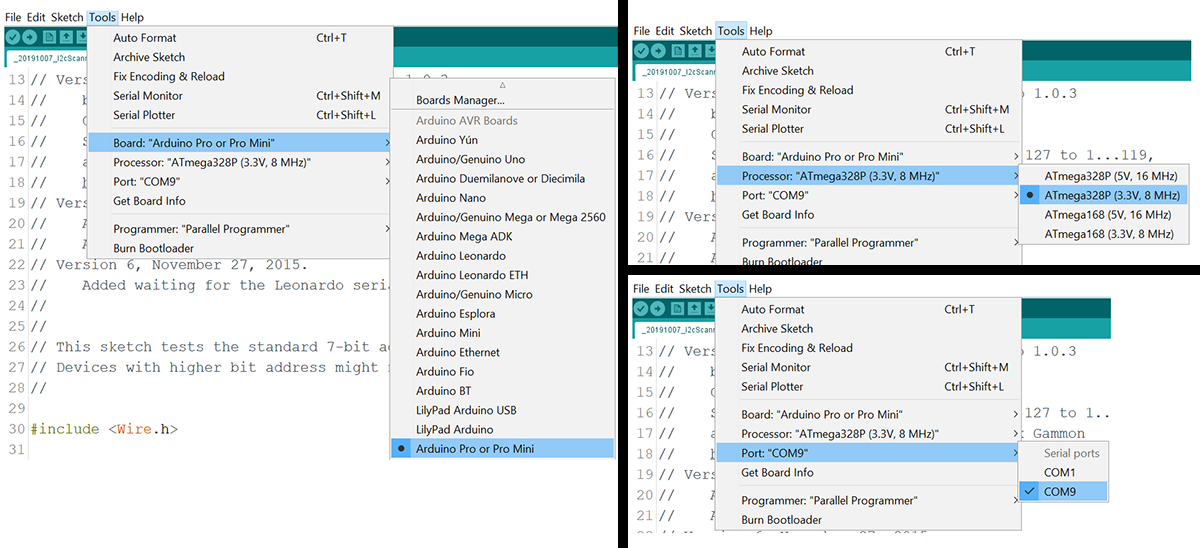
Note: that the “COM’ setting will be different for each computer, so you will have to look for the one that appears on your system AFTER you plug in the UART module.

Using 22AWG solid core jumpers to bridge a set of ‘power rails’ along each side keeps the wiring tidy. If you are using several I2C sensors you could also do this with those bus lines. After testing your prototypes, you can make them permanent by transferring your circuit to solder-able mini breadboards.
The one that’s easy to forget is choosing the 328P 3.3v 8Mhz clock speed. If you leave the 328p 5v 16mhz (default), the programs will upload OK, but any text displayed on the serial monitor will be random garbled characters because of the clock speed mismatch. Also be sure to disconnect battery power (by removing one of the AA batteries) whenever you connect your logger to a computer. There is no power switch on the loggers, which are turned on or off via the battery insertion. Use a screwdriver when removing the batteries so that you don’t accidentally cause a series of disconnect-reconnect voltage spikes which might hurt the SD card.
3. Test the LED – the default blink sketch uses the pin13 LED, but because that pin is shared with the SD card’s clock line it’s recommended that you test the RGB indicator instead by adding commands in setup which set the digital pin 4 act as the ground line for the LED:
pinMode(4, OUTPUT); digitalWrite(4, LOW);
Then change LED_BUILTIN in the blink code example to the number of a pin connected to your led module. (ie: for Red set it to 3, for Green use 5, or Blue use 6)
4. Scan the I2C bus with the scanner from the Arduino playgound. The RTC module has a 4K eeprom at address 0x56 (or 57) and the DS3231 RTC chip should show up at address 0x68.
The address of the eeprom can be changed via solder pads on the board, so it may have a different address. If you don’t see at least these two devices listed in the serial monitor when you run the scan, there is something wrong with your RTC module or the way it’s connected: It’s very common for a beginner to get some of the wire connections switched around during assembly but with the screw terminals this takes only a few moments to fix.
5. Set the RTC time, and check that the time was set – The easiest method would be to use the SetTime / Gettime scripts from our Github repository, but you first you need to download & install this RTC control library The SetTime script automatically updates the RTC to the moment the code was compiled (just before uploading) so only run SetTime once, and then upload the GetTime sketch to remove SetTime from memory. Otherwise SetTime will keep setting the RTC to the old ‘code compile time’ every time it runs – and one of the quirks of the Arduino environment is that it restarts the processor EVERY TIME you open a serial window. The SetTime script also has a function which enables the alarm(s) while running the RTC from the backup coin cell battery.
Note: the RTClib by Mr. Alvin that we use has the same name as the Adafruit library for this RTC and this can give you compiler errors if you let the IDE ‘auto-update’ all of your libraries because it will over-write the Alvin RTClib with Adafruit’s library of the same name. You then have to uninstall the Adafruit library ‘manually’ before re-installing Alvin’s RTClib again. This problem of ‘two different libraries with the same name’ was common back when this project started many years ago, but back then the IDE didn’t try to update them automatically.
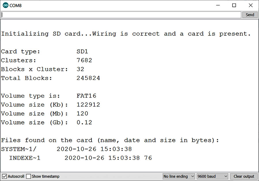
Typical Cardinfo output on a windows computer when the connections are correct. If you format your SD card on an Apple computer there will also be a long list of ‘invisible’ .trash and .Spotlight files/folders at the root of the SDcard that show up with a CardInfo scan.
6. Check the SD card with Cardinfo
Note that the SDfat library we use to communicate with SD cards works well with smaller cards formatted as fat16, but ‘some’ Apple users find they can not write to cards in that format, requiring the SD cards to be reformatted as fat32 (note that most Apple systems have no problem with the fat16 SDcards). With either OS you should format the micoSD cards with this SDFormatter utility. With a 15 minute sampling interval, most loggers generate ~ 5Mb of CSV format text files per year. Older, smaller SD cards in the 256-512Mb range often use less power. Note that we apply internal pullup resistors on some of the SD card lines in setup to help the SD cards go into low power sleep modes more reliably.
7. Calibrate your internal voltage reference with CalVref from OpenEnergyMonitor.
This logger uses an advanced code trick to read the positive rail voltage to ~11mv resolution by comparing it to an internal 1.1v bandgap reference inside the processor. That internal ref. can vary by ±10% from one chip to another, and CalVref gives you a numerical constant which usually brings the starter script’s rail=battery readings within ±20mv of actual. An accurate rail reading is more important when you are using ANALOG sensors where the positive rail directly affects the ADC output, but you can skip this procedure if you are only using digital sensors because they use their own internal reference voltages.
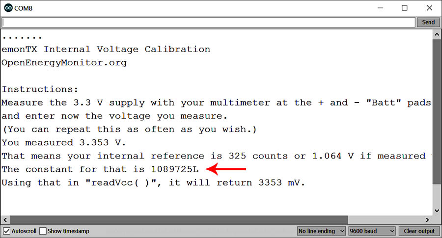
Typical CalVref output (click to enlarge)
Load CalVref while the logger is running from USB power and then measure the voltage between GND and the positive rail with a voltmeter. (this voltage will vary depending on your computer’s USB output, and the UART adapter you are using) Then type that voltage into the entry line at the top of the serial monitor window & press the enter key. Write down the reference voltage & constant which is then output to the serial monitor window. I write these ‘chip-specific’ numbers inside the logger with a black marker as they are related only to the 328p processor on the ProMini board used to make that particular logger. You then need to change the line #define InternalReferenceConstant 1126400L in our starter code to match the long number returned by CalVref. Alternatively you could just tweak the value of the reference constant ‘by hand’, increasing or decreasing the value till the reported rail readings match what you measure with a voltmeter. Add or subtract ~400 to/from the constant to raise/lower calculated output by ~1 millivolt. After you’ve done this once or twice you can usually reach the correct value with a few successive guesses.
8. Find a script to run your on logger. For test runs on a USB tether, the simplest bare-bones logger code is probably Tom Igoe’s 1-pager at the Arduino playground. It’s not really deploy-able because it never sleeps the processor, but it is still a useful ‘1-pager’ for teaching exercises and testing sensor libraries. In 2016 we posted an extended version of Tom’s code for UNO based loggers that included sleeping the logger with RTC wakeup alarms. Our current logging “Starter Script” has grown since then to ~750 lines, but it should still be understandable once you have a few basic Arduino programming concepts under your belt.
Using the logger for experiments:
It’s important to understand that this logger was designed a teaching tool rather than a off the shelf, plug-&-play solution. Learning how to solder and getting some experience physically ‘putting things together’ are key outcomes. Wrangling code into shape driving some new sensor combination is another vital part of that process. So perhaps the best piece of advice I can give to new builders is:
Test, Test, and when you think your logger working: Test it Again
It’s nearly impossible to write code without little bugs and the only way to root them out is with multiple test runs. And even if the script you wrote is ‘perfect’ the processors on the sensor modules are also running code that you don’t have access to. For example, the mcu inside your SD card memory is more powerful, and may have more code on it than the ProMini at the heart of this logger. The only way to catch timing errors that might not get triggered until the 10th or 200th(?) pass is to run your code with a short 1 minute sampling interval until it’s crossed those roll-over thresholds many times. Use “Starting sensor X read” & “Finished sensor X read” print statements liberally during early USB tethered tests so you can observe the timing of events.

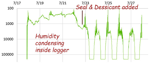
If you see water condensing like this on the lid of your logger then it’s time to examine the o-ring and add some extra sealant (nail polish or silicone) around the exterior of the cable glands. This logger quit after one week and it only lasted that long because of the desiccant pack.
Same thing applies to the sensor hardware in terms of durability, only now you have moisture to deal with. Everything that can be sealed in adhesive lined heat shrink, or potted in epoxy should be, once that hardware has passed your ‘dry’ tests. As a general rule no $10 sensor is going to be rated past IP68 which at best gives you 2-3 weeks of operation in the real world before water works it’s way in because of pressure imbalances caused by daily thermal cycling. You’d be surprised how easily moisture can wick along the air space ‘between the copper strands’ inside wires.
A doubling schedule works well for testing: Check the logfile at 1 hour, 2 hours, 4 hours, overnight, 1 day, 2 days, 4 days, 8, 16, 32… etc. Move to the next longer test only when the data from the previous run is confirmed. Keep a close eye on that battery burn down rate: Until you get the hang of putting your sensors into low current ‘sleep’ states – getting your first logger builds to run for a couple of months on new batteries should be considered a spectacular success. At every startup watch and wait for the pattern of LED flashes to confirm that the launch went smoothly – it is very easy to insert a battery or SD card crooked by ‘just enough’ that the unit does not start, and it’s very frustrating to discover you have no data a week later.
You never really know how long a sensor is going to last until you’ve deployed it – no matter what the manufacturer says in the data sheet. Even then we usually deploy three of every ‘new’ combination, and if we are lucky we get one complete data set for the year. Batteries leak, critters love to chew on things, and whenever humans come across something they’ve not seen before they will pick it up – especially if you had to invest a good deal of time securing your logger in exactly the correct position in the stream, on the tree, etc. We never deploy anything for real research until it has passed a several week-long rapid sample ‘burn-in’ test.
One positive aspect of the relatively loose fit of the Plano box lid is that it lets you run sensor tests quickly if you jumper your sensor module with thin 28-30 gauge wires:
 A BMP280 pressure sensing module on long wires with crimped male dupont ends in the breadboard. |
 ~1″ square of foam mounting tape with wires spaced evenly |
 Leave the red backing facing up as you fold the tape & wires over the corner edge. |
 The front corners of the box exert less pressure than the back corner shown here. |
 The sharp inner edge of the lid would cut the wire insulation if the tape was not there to protect, and even then you can only use this trick a few times. |
 The tape over the wires has to be replaced every time. |
This gives you a chance to do some test runs before you commit to modifying the housing with holes or cable glands. For some indoor experiments this might be all you actually need, though I would still coat the ‘non-sensing’ parts of that dangling breakout with either conformal coating or clear nail polish. My general advice is: Do not put holes in the housing unless you are sure you need them. The most common failure mode for student loggers used in outdoor environments is from moisture seeping into the through the cable gland. Natural heating and cooling cycles creates pressure differences between the inside and outside of the logger that drive this vapor exchange. Moisture then condenses when temperatures fall at night, collecting on leftover flux residue to corrode contacts. An outer layer of self-fusing rubber mastic tape is often used on cable glands by electricians on out-door installations – even when using the expensive ones with soft rubber ‘cages‘.
After 1-2 minutes of kneading to mix the epoxy you have ~ 1 minute to work the putty into place. (it will become rock-hard within ~10 minutes). Be sure to leave yourself enough extra wire/space inside the housing so that you can open and close the lid easily without disconnecting anything after the putty hardens. This seal is not strong enough for underwater deployments, but it should easily withstand exposure to rain-storm events. HOT GLUE also works to seal pass-through ports with smaller wires & cables. Both pass-through methods can be helped by a layer of silicon caulking, nail polish, or conformal coating applied to the outside edges.
For a classroom project you could simply drill small a hole through the lid and stick the sensor/module on top of the housing, sealing the hole with double-sided tape. Thicker pass-throughs can be also be sealed reasonably well with plumbers epoxy putty which is non-conductive, and adheres quite well to metal, glass & plastic surfaces-> This putty is also a quick way to make custom mounting brackets, or even threaded fittings if you wrap it around a bolt (which you carefully remove before the putty hardens completely)
No matter which pass-through method you are using: Silica gel desiccant packs are important for any outdoor deployments and 5-10 gram packets are a good size for this logger.
Don’t subject these loggers to a lot of bashing around by deploying them in a rough surf-wash zone, or swaying freely in the wind off the end of a tree branch. Solid core wires are pretty good if you cut them to exactly the right length , but longer beadboard jumpers are very easy to bump loose, so once you have your prototype working, it’s usually best to re-connect the sensors directly to the screw terminals before deploying a logger where it could get knocked around. In a pinch you can secure breadboard pins with a small drop of hot glue to keep them from wiggling. Also remember that there are six ‘unused’ screw terminals on the base shield and these can be use to join wires together without soldering.
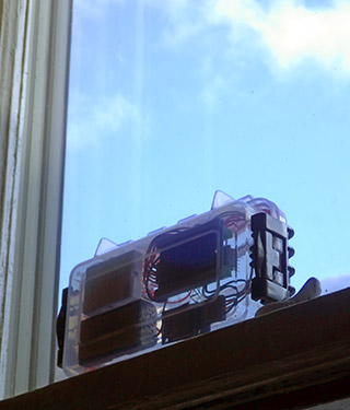
2019 Logger mounted on a south-facing window. The top surface was covered with white label-maker tape to act as a diffuser.
[Click HERE] to read about the many types of sensors can be added to this logger The transparent enclosure makes it easy to do light-based experiments. Grounding the indicator LED through a digital pin allows it to be used as both a status indicator, and as a light sensor. The code we use is a polarity reversal technique that relies on the tiny capacitance inside the LED. (~5 to 20pF & the processor port adds 10pF) This technique requires the LED to connected directly to ProMini inputs because breadboards can add random amounts of changing capacitance. At these sub pF ranges, any humidity that condenses between the pins will also upset the readings, so desiccants are required. And finally the reverse bias decay is affected by the starting voltage, so if you want to use the technique in a rigorous ‘analytical’ setting you should leave the regulator on your logger.
We have integrated this LED sensor technique into the starter script on GitHub. I’ve tweaked the playground version with port commands so the loop execution takes about 100 clock cycles instead of the default of about 400 clock cycles. The faster version was used to generate the following light exposure graph with a generic 5mm RGB LED, with a 4k7Ω limiter on the common ground.

Red, Green & Blue channel readings from the indicator LED (from a regulated logger) over the course of one day (logger photo above) The yellow line is from an LDR sensor the same unit, that was over-sampled to 16-bit resolution. The LED sensor has a logarithmic response and the left axis on the graph is a time- based measurement where more light hitting the LED sensor results in a lower number. Note how the RED signal changes before/after Blue & Green at sunrise & sunset. LED’s work well with natural full-spectrum light, but their limited frequency bands can give you trouble with the odd spectral distribution of indoor light sources. The peak response of LED’s is usually 30–50nm lower than their peak emission wavelength If we assume the Red was Aluminum gallium arsenide (AlGaAs) then that channel probably had an absorption band @ ~680 nm (~15 nm FWHM?) while the blue Indium gallium nitride (InGaN) channel is responding in the UV-A range, the Green channel (probably also InGaN ?) is most likely peaking around 420nm which is blue to our eyes. But without a spectrometer to test, these are just guesses. No temp. or cosine corrections were determined/applied, although blue/green channels tend to have low temperature coefficients because their bandgap is so far from the thermal spectrum. LED absorption bands have very little drift over time.
You can read more about LED based sensing techniques in the post about our leaf testing experiments which used two LEDs for a transmission-based variant of the NDVI ratio.
While the LED sensor idea is fun to work with, it’s a relatively slow method that can keep the logger running for many seconds when light levels are low. Figuring out how to take those light readings only during the day is a good coding exercise for students.
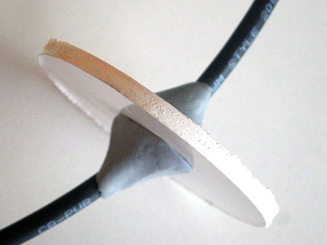
Note: VERY FEW light sensors can withstand exposure to direct sunlight. PTFE is an excellent light diffusing material which available in different sheet thickness. The ‘divot’ on the lid of the Plano box is just a bit larger than 55mm x 130mm x 3mm (depth). The “teflon” tape that plumbers use to seal threaded joints can also be used. PTFE introduces fewer absorbance artifacts than other DIY diffusers like ping-pong balls, thermoplastic, or hot melt glue. Most light sensors like the TSL2561 need 3-5mm of that PTFE sheeting to prevent the sensors from saturating in full sun. LED’s have logarithmic response so you lose quite a bit of detail above 40,000 lux unless you add a diffusion layer to attenuate the signal.
Full sun exposure can also cook your logger. Internal temps above 80°C may cause batteries to leak or damage the SD card. So if you are leaving the logger in full sun, add a bit of reflective film or some aluminum foil around the outside to protect the electronics. Of course if you have a light sensor you’ll need to leave some ‘window area’ for it to take a reading.
The RTC has a built-in temperature register which automatically gets saved with our starter script however that record only resolves 0.25°C, so we’ve also added support for the DS18b20 temperature sensor to the base code. A genuine DS18b20 (yes, fake sensors are a thing) draws very little power between readings and you can add many DS18b’s to the same logger.
Addendum: Diagnosing Connection Problems
If you successfully loaded the blink sketch to test the ProMini during your initial assembly, then issues during the testing stage are often due to incomplete connections to the I/O pins.
If you see only “Scanning I2C….. ” but nothing else appears when running the bus scanner, then it means that the ProMini can not establish communication with the RTC module. One common cause of this problem is that the white & yellow wires have been switched around at one end or the other. It’s also easy to not quite remove enough insulation from the wires to provide a good electrical connection under the screw terminals, so undo those connection and check that the wires were stripped, cleaned & wrapped together before being put under the terminals.
Scanner lockup can also happen if one of the I2C devices on the bus is simply not working: usually about 1 in 6 logger builds ends up with some bad component that you have to identify by process of elimination. (These are 99¢ parts from eBay…right?) It only takes a moment to swap in a new RTC board via the black Dupont connector and re-run the scan. If the replacement RTC also does not show up with the I2C scanner then it’s likely that one of the four bus lines does not provide a complete connection between the ProMini & the RTC module.
On this unit I measured 1 ohm of resistance on the I2C clock line between the ProMini A5 pin (on top of the board) and the SCL header pin on the RTC module. So this electrical connection path is good. It’s not unusual for each ‘dry’ connection to add 0.5-1 ohm of resistance to a signal path.
To diagnose: Unplug any power sources to the logger. Set a multi-meter to measure resistance and put one probe lead on the topmost point of the promini header pins, and the other probe on the corresponding header pin of the RTC module. If there is a continuous electrical connection between the two points then the meter should read one ohm or less. Higher resistances mean that you don’t have a good electrical path between those points even if they look connected:
1) the ground (black) wire should provide a continuous path from the ground pin on the digital side of the Promini board to the GND pin on the RTC module
2) the positive power (red) wire should provide a continuous path from the Promini positive rail pin (the one with the bundle of 4 red wires) to the VCC pin on the RTC
3) A4 (I2C data) near the 328P chip on the Promini must connect all the way through the screw terminal board and through the white Dupont wires to the SDA post on the RTC
4) A5 (I2C clock) nearest the UART end on the Promini must connect through through the yellow Dupont wire to the SCL header on the RTC .
You occasionally get a bad Dupont wire where the silver metal end is not in contact with the copper wire inside because the crimp ‘wings’ did not fold properly. With a pair of tweezers, you can ‘gently’ lift the little plastic tab on the black shrouds holding the female Dupont ends in place, and then replace any single bad wire. Be careful not to break the little black tab or you will have to replace the entire shroud.
Everyone uses short male-to-male Dupont jumper wires when they are creating test circuits because they are so convenient. But pre-made jumper wires are usually too long and so they get knocked around when you close the lid of the logger: so before you deploy take the time to convert your flexible-wire test circuit into one with solid core jumpers:
 Flexible wires get used during the initial testing stages (when the lid of the logger is open). |
 Then the circuit gets re-done with solid core wires |
 Running wires ‘under’ the modules makes it easier to close the lid without disturbing the connections. |
Also look at the little jumpers used to bridge the A4>A2 and A5>A3. If you have a ‘cold’ solder join, or an accidental bridge connection to something else, it could stop the bus from working. Re-melt each connection point one at a time, holding the iron long enough to make sure the solder melts into a nice ‘liquid flow’ shape for each solder point.
The connection diagnosis procedures described above also apply to the connections for the SD adapter board. Sometimes you end up with an adapter that has a defective spring contact inside the SD module, but the only way to figure that out is to swap it with another one.

Here a jumper wire from the ProMini pin is by-passing a bad connection on the screw terminal board. This is also how you would break out A6 & A7 if you need them.
Sometimes those screw terminal boards have a poor connection inside the black female headers below the ProMini. It’s also possible to accidentally over-tighten a terminal and ‘crack’ the solder connection below the board – or there may simply be a cold solder joint on one of the terminal posts. If you have only one bad connection, you can jumper from the ProMini header pins on top, down to the other wires under the corresponding screw terminal. If you accidentally strip the threads on a screw terminal, you can use this same approach but move that set of wires over to one of the three ‘unused’ screw terminals at the far end of the board. (beside the SD card adapter) If you’ve gotten through all of the above steps and still have not fixed the problem, then it might be time to simply rebuild the logger with a different screw terminal adapter board.

If you do accidentally kill the ProMini by shorting a pin, etc, you can carefully lever it up away from the screw terminal shield and replace it without having to rebuild the whole logger.
Build two loggers at a time, because that lets you determine whether problems are code related (which will affect both machines the same way) or hardware related. (which will only affect one of your two units) At any given time I usually have 2-3 units running overnight tests so that I can compare the effect of two different code/hardware changes the next morning. As a general rule you want to run a new build for at least a week before deploying to get beyond any ‘infant mortality’, and reach the good part of the bathtub curve.
An I2C OLED is quite readable through the lid of the housing. I often use Griemans text-only SSD1306Ascii library because it has a low memory footprint and sleeps well. While few loggers need live output when they are deployed, it’s often helpful to view diagnostic messages on battery power during testing. Adding two OLED displays let’s you view text & graphic output at the same time. Adding a capacitive touch switch lets you check your logger’s status at any time.
Addendum: A note about I2C sensors
The I²C bus is slow, so topology (star, daisy-chain, etc.) doesn’t matter much, but capacitance does. Both length & number of sensors increase capacitance. If you find that the devices work when you switch to a slower speed (e.g. 50 kHz), then this is probably your issue, and you need to minimize bus length and/or maybe decrease the combined resistance of the pull-ups to 2 kΩ or less. The DS3231 RTC module has 4k7 ohm pull-up resistors on the SDA & SCL lines & the Pro Mini adds internal 50k pull ups when the wire library is enabled. Typical I2C sensor modules usually add another set of 10k pullups so your ‘net pullup resistance’ on the I2C bus wires is usually: 50k // 4k7 // 10k = ~3k. With a 3.3v rail that means the devices draw 3.3v / 3k = 1 mA during communication which is fairly normal ( 3mA is max allowed) for total wire lengths below 1m. It’s common for pre-packaged sensors to arrive with housings at the end of about 1m of wire. If each sensor also adds another set of 10k pullups, the resistance generally compensates for the extra wire length, so the combination still works OK. But that depends on the cable too. A very bad cable might not even get to 0.5 meters and a very good cable (little capacitance to ground, no crosstalk between the wires) can go up to 6 meters.
For most sensor types there will be some options that draw much less power than others, and it’s always worth a look at the data sheet to make sure you are using one that will run longer. The best chip based sensors automatically go into low current modes whenever the bus has been inactive, but more often you need to ‘manually’ put the sensors to sleep via specific commands. So it’s also important to check if your sensor library supports those ‘go to sleep’ & ‘wake up’ commands – many common Arduino libraries do not.
Addendum: The importance of moisture protection
I was noodling around in the garden recently and installed a few loggers without desiccants because it was only a short experiment. It rained immediately afterward and I noticed a small amount of moisture condensed inside the plano-box housing. While this didn’t prevent the logger from functioning, it completely disrupted the LED light sensors because the increased humidity provided an alternate discharge path for the reverse bias charge on the LED’s:
Green channel data from a 5mm diffused RGB LED used as light level sensor. This logger was under some leaf cover, so there was considerable variability from the dappled light crossing over the sensor. An arbitrary cutoff of 200,000 was set in the code at low light levels.
After examining the O-ring I decided to add a little silicone to the channel holding the o-ring to improve the seal:
 Gently pry the O-ring loose and apply sealant in the groove before replacing. |
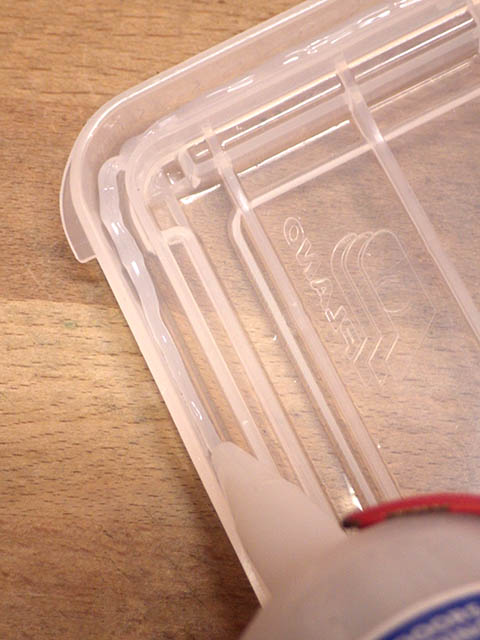 Bead only needs to be 3-4mm in diameter. |
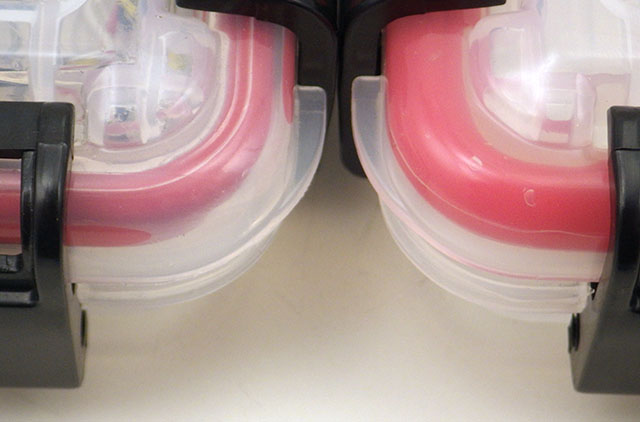 Close the housing & let the sealant set for a few days. The improved seal is especially visible at the corners |
 If you already have your logger assembled, try to find a silicone sealant that does not off-gas acetic acid (smells like vinegar) which could harm your circuits. If you are simply preparing empty boxes before assembly, then any regular bathroom sealant will do provided you give it about a week to finish curing.
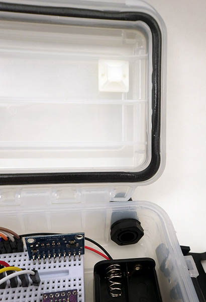
Attach a mounting base to the lid so that a dessicant pack can be secured above the battery holder without interfering with any breadboard jumpers. Use a desiccant pack with color indicator beads, so you can check whether they are still working simply by looking through the transparent lid.
Addendum: If you want to leave the original regulator in place
It’s worth mentioning that an unregulated build will run for many months – even on 2x regular alkaline batteries which reach the system cutoff (at 2750mv) more quickly. The key deciding factor is whether your sensors require tight voltage regulation. The DS18b20 has a nominal low voltage limit of 3v. So if your project is making heavy use of those then there are only a few of modifications to the tutorial shown above to leave the ProMini’s default MIC5205 regulator in place:
 Use straight header pins on the RTC modules cascade port to leave more space for the battery holder. |
 Only bridge the unused RST terminals to the rail connections – Leave the Vin terminal separate for the raw battery input. |
 Add a 10/3.3 Meg voltage divider to read the raw battery voltage on A0 |
You will need more space for the extra batteries. You could go with a 3xAA holder but that leaves about 50% or your alkaline battery capacity unused. Or you could keep the standard layout and use 4xAAA batteries.
 An alternative would be to add a better regulator to some kind of intermediate battery connector. The the photo on the right shows two ceramic 105’s stabilizing an MCP1702-3302E/TO, while the 10/3.3M ohm divider provides a third output line so the ADC channel can monitor the raw battery voltage. This is the simplest way to retro-fit a unit that was built without a reg, with the added benefit that the new regulator is far more efficient than the original MIC5205 on the ProMini. It’s worth noting that even on a regulated logger you can monitor the rail voltage to determine when the main batteries are depleted because the regulators output will fall if the batteries reach a point below the minimum dropout voltage. If the rail falls under load by more than ~40mv, then it’s probably time to shut down the logger. With the regulator in place you probably don’t need the USB isolator, as the reg. itself cant pass more current than a USB port.
Addendum: Things to keep in mind when ordering parts
When a finished module arrives at your doorstep for less than you’d pay for any of its sub-components – it’s because you are doing the quality control.
My advice is to order at least 5-6 of each of the core components (Promini, RTC, SD module, screw terminal board, etc) with the expectation that about 10% of any cheap eBay modules will be DOA or have some other problem. I build in batches of six, and one logger typically ends up with a bad part somewhere. Having replacement bits on hand is your #1 way to diagnose and fix these issues. Bad parts tend to come “in bunches”, so if you scale up to ordering in quantities of 10’s & 20’s then spread those orders to a few different suppliers so you don’t end up with all your parts from the same flakey grey market production run. Order from different vendors in different odd-number quantities (11, 21, 9, etc.) because that will be the only way you can distinguish which supplier, sent which parts, because nothing on the package will be written in English.
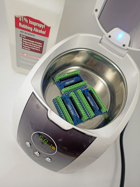
The other thing I can’t stress enough is CLEAN ALL THE PARTS as soon as they arrive. Leftover flux is very hygroscopic, and solder points will start to corrode the moment your logger gets exposed to atmospheric moisture. I usually give everything about 10 minutes in a cheap sonic bath with 90% isopropyl alcohol, rinse with water, and then dry the parts out in front of a strong fan for an hour. Clean parts that can’t take the sonic vibration (RTC modules, humidity sensors, accelerometers, etc) by hand with a cotton swab. Then store parts in a sealed container with desiccant packs till you need them. I also coat the non-sensing/non-contact surfaces with a layer of MG Chemicals 422B Silicone Conformal Coating and let that dry for a day before assembling the loggers. One hint that you may have moisture issues is that the sensors seem to run fine during indoor tests but start to act strangely when you deploy the unit outside.

Used nut containers make excellent “dry storage” once the parts have been cleaned – but any air-tight container will do.
Another insight I can offer is that the quality of a sensor component is often related to the current it draws – if your ‘cheap module’ is pulling significantly more power than the data sheet indicates, then theres a good chance it’s a junk part. Usually if the sleep current is near spec, then the sensor is probably going to work. It is much easier to check low currents with a µCurrent or a Current Ranger. (I prefer the CR for it’s auto-ranging features) Sensors which automatically go into low current sleep modes take time – so you might need to watch the current for several seconds before they enter their quiescent states. A common reason for a short operating lifespan on a logger is an SD card that refuses to go into sleep mode. If there is an SD card connected to your logger you must initialize it (with sd.begin in setup) or it may ‘stay awake’ causing a constant 30-40mA drain and/or may even cause the logger to freeze up. Also with SD cards, if the freshly formatted throughput drops below its rated write speeds when tested with H2testw, then find another card to use. I avoid cards bigger than 2Gb because they usually draw too much current, and it’s rare to need that much space for a logger.
With cheap part variation & beginner soldering skills, student builds range from 0.15mA to .5mA sleep current. But even at that high end you should still get a couple of months of operation of from the logger on fresh batteries.
| Bill of Materials: | ~$22.00 | ||||
|---|---|---|---|---|---|
| Plano 3440-10 Waterproof Stowaway Box Sometimes cheaper at Amazon. $4.96 at Walmart and there are a selection of larger size boxes in the series. 6″ Husky storage bins are an alternate option. |
$5.00 | ||||
| Pro Mini Style clone 3.3v 8mHz Get the ones with A6 & A7 broken out at the back edge of the board. Just make sure its the 8 MHz 3.3v version because you can’t direct-connect the SD cards to a 5v board. Watch out for non Atmel 328p chips. |
$2.20 | ||||
| ‘Pre-assembled’ Nano V1.O Screw Terminal Expansion Board by Deek Robot, Keyes, & Gravitech (CHECK: some of them have the GND terminals interconnected) You will also need to have a few 2.0-2.5mm flat head screw drivers to tighten those terminals down. Since this shield is was originally designed for an Arduino Nano many of the labels on ST board will not agree with the pins on the ‘analog side’ of the ProMini. |
$1.85 | ||||
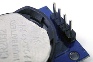
| DS3231 IIC RTC with 4K AT24C32 EEprom (zs-042) Some ship with CR2032 batteries already installed. These will pop if you don’t disable the charging circuit! |
$1.25 | ||||
| CR2032 lithium battery | $0.40 | ||||
| SPI Mini SD card Module for Arduino AVR Buy the ones with four ‘separate’ pull-up resistors for removal if you decide to mosfet-switch the SD power lines. |
$0.50 | ||||
| SD card 256mb -to-1Gb Test used cards from eBay before putting them in service. Older Nokia 256 & 512mb cards have lower write currents in the 50-75mA range. This is less than half the current draw on most cards 1gb or larger. I tend to avoid older cards labeled as ‘TransFlash’ because they seem to have more controller artifacts during saves. Small 128mb & 256mb cards under the name Cloudisk have appeared on eBay, and so far they seem to be working ok. |
$2.00 | ||||
| Small White 170 Tie-Points Prototype Breadboard These mini breadboards for inside the logger are also available in other colors. |
$0.60 | ||||
| 30cm Dupont 2.54mm M2F 40wire ribbon cable Dupont connector hook-up wires might be expected to add an ohm or two of resistance and carry at most 100mA reliably with their thin 28-30 gauge wires. Each 40-wire cable will let you make at least 2 loggers. |
$1.55 | ||||
| 10cm Dupont 2.54mm M2F ribbon cable Sometimes these 10cm cables are harder to find, so you can just use the longer 20cm wires in a pinch. It’s usually also helpful to have a few Male-to-Male 10cm cables for interconnections on the breadboard. |
$1.00 | ||||
| 2×1.5V AA Battery Batteries Holder w Wire Leads If you are running an unregulated system on 2 lithium batteries, then you can use a 2x AA battery holder. If you need to keep the regulator in place to stabilize the rail voltage for particularly picky sensors, use alkaline batteries and a 4xAA battery holder. Watch out for ‘cheap’ battery holders with weak plastic at the connection ends which will slowly bend away from the batteries until they pop out in warmer climates. If that happens you can add a zip tie belt around the holder to keep the cells in place when the plastic softens. |
$0.50 | ||||
| 5mm Common cathode RGB LED Although you might want to use 10mm LEDs to increase surface area when using the LED as a light sensor. They also look better. |
$0.10 | ||||
| M12 Nylon Cable Glands (pack of 20 pcs) You will also need some extra rubber washers. |
$0.70 /2pcs | ||||
| 3.3V FT232 UART Module (get at least 2-3 modules – they are easy kill with a brief short) *jumper the pads on your UART module to 3.3v output before using it!* You will also need a few USB 2.0 A Male to Mini B cables. You may need to install drivers from the FTDI website depending on your OS. These boards can only supply ~50mA which can be tricky if your sensors need more for sustained periods. If you are running the class via distance learning it’s probably a good idea to also get some CP2102 (c231932) UART boards and send your students one of each type. If they are unable to get the drivers working for the FT232, they have a second option. You may have to hunt around for non-FTDI chip boards with the same pin order as the ProMini [ DTR-RX-TX-3v3-CTS/gnd-GND ] The DTR pin is critical for uploading code, while the CTS (clear to send) is an input pin for the FTDI chip only and CTS is not used by the ProMini (so it’s usually just tied to ground). So many UART adapters only have 5 connections and you have to cross the wires over each other to get the connections sorted out. Watch out for 6-pin UART modules that put a (+)ive power connection in the same physical alignment as the GND connection on the ProMini – those boards can create a short circuit unless you re-route the wires. It’s also worth knowing that UARTs can communicate directly to serial sensors like GPS modules for testing. Premade 30cm 6-pin Dupont jumper cables are also available.. |
$2.75 | ||||
| 3M Double-side Foam Tape, LEDs, header pins, 3/4 inch zip Tie Mounts, etc… I use 30lb ‘outdoor’ or VHB (high bond) foam tape, each logger takes ~30cm length |
$1.00 | ||||
| Some extra tools you may need to get started: (not included in the total above) | |||||
| 2in1 862D+ Soldering Iron & Hot Air station Combination a combination unit which you can sometimes find as low as $40 on eBay. Or you can get the Yihua 936 soldering iron alone for about $25. While the Yihua is a so-so iron, replacement handles and soldering tips cost very little, and that’s very important in a classroom situation where you can count on replacing at least 1-2 tips per student, per course, because they let them run dry till they oxidize and won’t hold solder any more. Smaller hand-held heat-shrink guns are available for ~$15, $10 80Watt-AC & $5 USB soldering irons are quite useable. |
$15.00 – $50.00 | ||||
| SYB-46 270 breadboards (used ONLY for soldering header pins ) Soldering the header pins on the pro-mini is MUCH easier if you use a scrap breadboard to hold everything in place while you work. I use white plastic breadboards that only have one power rail on the side since I won’t mistake them for my regular breadboards. I also write ‘for soldering only’ on them with a black marker. |
$1.30 | ||||
| SN-01BM Crimp Plier Tool 2.0mm 2.54mm 28-20 AWG Crimper Dupont JST I use my crimping pliers almost as often as my soldering iron – usually to add male pins to component lead wires for connection on a breadboard. But making good crimp ends takes some practice. But once you get the hang of it, Jumper wires that you make yourself are always better quality than the cheap premade ones. |
$16.00 | ||||
| Micro SD TF Flash Memory Card Reader Get several, as these things are lost easily. My preferred model at the moment is the SanDisk MobileMate SD+ SDDR-103 or 104 which can usually be found on the ‘bay for ~$6. |
$1.00 | ||||
| Side Shear Flush Wire Cutters & Precision Wire Stripper AWG 30-20 HAKKO is the brand name I use most often for these, but there are much cheaper versions. |
$5-10 | ||||
| Dt380 Multimeter Dirt Cheap & good enough for most classroom uses. |
$3.50 | ||||
| Syba SY-ACC65018 Precision Screwdriver Set A good precision screwdriver set makes it so much easier to work with the screw terminal boards. But there are many cheaper options. The screw terminal boards need 2mm (or less) flat slot tips. |
$12.00 | ||||
| Donation to Arduino.cc If you don’t use a ‘real’ Pro Mini from Sparkfun to build your logger, you should at least consider sending a buck or two back to the mother-ship to keep the open source hardware movement going… |
$1.00 | ||||
.. and the required lithium AA batteries are also somewhat expensive, so a realistic estimate is about $25-30 for each logger when you add a couple of sensors. Expect parts from low-end suppliers to take 4-6 weeks to arrive and always order at least 50% more than you actually need so you have spares. If you’re pressed for time everything on this list is also available from trusted first-tier suppliers like Sparkfun, Adafruit, Pololu, etc – but you will pay 5-10x as much, with an additional $10-15 shipping charge unless you pass the minimum order level. Amazon is now in a kind of weird grey zone between the two as many vendors that sell on eBay, are also selling on Amazon for 2-3x the price.
Addendum: Using a more advanced processor
Moteino MEGA based Cave Pearl Logger
After you’ve built a few ProMini based loggers, you might want to try a processor upgrade. The 1284p CPU has twice the speed & 4x the memory, but delivers comparable sleep current & operating life.
Addendum: Low Temp. effects on 2x Lithium powered logger
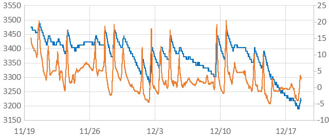
2x LithiumAA millivolts (blue-left) vs RTC Temp °C (orange-right) on cells that have been in service for 5 months. We will leave this unit running over winter to see how DS18b20 on that logger handles it if/when the cells fall below the DS18’s 3V minimum, and then rise back up again. (click image to enlarge)
A crop of these loggers have been running in our back-yard garden since mid-summer with various sensor combinations. Winter is finally reaching us so we can now observe how the cold affects an unregulated 2x Lithium AA supply. This ‘student build’ sleeps at ~170uA and has been running for five months. The battery curve was virtually flat above 15°C but it is now being quite strongly affected. Peak loads from the SD card are in the range of about 150mA and the unit is running with a 5 minute sampling interval.
Note: 2022-10-01: We’ve had several unregulated 2xLithium cell loggers running over winter now, with temperatures varying from -20°C to +40°C throughout the year. On units where the sleep current is in the low 20uA range, we typically see the voltage supplied by two cells in series vary due to that that 60 degree range from a low of 3350 to about 3550 mv on hot summer days. So about 200mV thermal delta in normal environmental conditions.
According to Energizer: In ultra-low drain applications like these dataloggers, the discharge curve has a distinct two stage profile. The first ‘very flat’ plateau occurs at slightly higher voltage (nominally 1.79V (or ~3.58v for two cells) @ 21°C) is nearly independent of depth of discharge. This unchanging stage lasts for about 2/3 of the batteries lifetime. The second stage occurs at a slightly lower voltage (nominally 1.7V (or ~3.4v for two cells) @ 21° C) where the cell voltage then decreases slowly as a function of depth of discharge. In my longer run tests, when the two lithium AA cells in series have fallen below ~3.1v, it’s time to shut down the logger.
Addendum: Adding a TTP233 Capacitive Switch lets you check your logger ‘any time’

With a capacitive touch switch that works through the housing, you can check the status of your logger at any time.
Our next tutorial post in the student logger series: Enhance your Logger with an OLED & T233 Capacitive Touch Switch is an excellent ‘next step’ for people using this logger in a classroom setting. The method is easily adapted to trigger ‘opportunistic’ readings in environments that require manual control, but it’s also handy when you need to check the battery level on a complex installation that you don’t want to disturb before the end of the experiment.
Addendum: Another fine crop of student loggers this year!


A 2-Part ‘mini’ logger released in 2023
Dr. Beddows instrumentation students have been building this Plano-boxed logger for years, and the ability to swap sensors or add an OLED screen has allowed continuous course development. But for those wanting a simpler ‘bare-bones’ version we’ve developed a 2 module classroom logger using 3D printed rails. Without the SD card this unit is memory constrained, and data download is handled via through the serial monitor window in the IDE. This model requires fairly detailed soldering so students get a complete practice lab soldering header pins onto perf-board before attempting the assembly. Running from a coin cell required the addition of several more advanced code techniques than the 2020 student logger at the beginning of this post. But for instructors, this is the least expensive option that still provides your students with an opportunity to change the sensors to develop their own projects.
