
Hi everyone. I wrote most of this entry on a plane today, as it was almost the first free time I’ve had “away from the workbench” since the initial proof of concept loggers were deployed last year. I have redesigned the Cave Pearl data loggers into a more modular platform that should be flexible enough for quick field repairs, while enabling future development with more sensors. (I want at least CTD, and my wife has an infinte supply of other suggestions 🙂
The loggers are now assembled in four interchangeable components, which from top to bottom are:
1) Upper housing

It was too cold in the basement for the epoxies to set
Lots of lessons have been learned here about sealing the hull penetrations thanks to the diy ROV crew. Sort lengths of 3/4 pipe form “wells” to protect the sensors, with JB Plastic Weld putty wrapped around the wires as they initially pass through from the inside of the housing. The putty sets on the roughened surface, pluging the hole and holding the sensors in position, but I found that the silicones I tested flex quite a bit after curing, so they are too easily “sheared” away from the pvc surface. As a result, the current builds use JB weld around the DS18B20 thermal sensors, and Loctite E-30CL to for a transparent seal over the “heartbeat” LEDs which pip when the samples are taken. Experience has shown me that you must have some way of knowing your units are working happily (or if they are in an error state…) before you dive them into the cave.
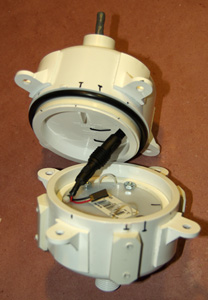
2) Main electronics platform

The LED is an Octopus Brick because they had a good buckled connector, and the RTC is a cheap DS3231 module from eBay because I wanted to use the AT24C32 eeprom it also had on board.
I am still quite happy with Tinyduino, as the package integrates the mcu, accelerometer, and now digital compass, with the smallest footprint and the least amount of extraneous wiring. I put riser pins on their new overhanging protoboard, and this jumps out to a grove I2C hub as a central interconnect system allowing me to interchange the logger platform with housings that will sport different sensors in future. All of the electronic components have had a good bath of conformal coating this time around, so hopefully they will be a bit more robust. (I might try Rustoleums Neverwet next time)
3) Power supply
The gap between the two shells provides room for the interconnect, and some filtering caps, etc. if needed.
Physically it’s just two pvc knockout caps held together with four bolts & a 1cm “hold down ring” to keep it in place in the lower housing. Electronically there are two versions. The first is an unregulated supply uses two banks of 3 AA batteries, through Shottky diodes to prevent the banks from draining unequally. This supply will drop from 4.5 volts down to a lower cutoff of 2.8 volts before the system stops logging, so it needs fairly robust sensors. The second power supply uses three banks of 2 AA batteries (with three Shottky’s) feeding into an NCP1402 3.3 volt boost regulator which then powers the logger. Several of the sensors I want to use have a strict 1.8-3.3v input range, so they can not be used with an unregulated system. It will be interesting to see if the greater “draw-down” enabled by a boost regulator compensates for the power it wastes (here about 25%). This deployment will hopefully be some months long, so I will find out how the regulated VS unregulated systems actually perform.
4) Lower housing & external weight system

This series needs about 100-150 grams of ballast mass to be neutral.
The buoyancy troubles we had on the initial deployment showed me that I needed some form of external system to compensate for changes in battery mass, cable buoyancy, salinity, etc. So I have a simple solution using a bolt through a threaded end cap which holds a number of washers as ballast. All stainless steel, but I am curious to see how long they actually last in the near marine environment. The buoyancy mass will be spit evenly on the top & bottom of the units to prevent rotational torques which which would affect the angle readings.

The battery run down tests are still looking very good for one year + deployments!
So this is the new fleet: Four pendulum units and one high resolution temperature & pressure sensor that will remain stationary. Hopefully they will all be underwater logging in a few days. Looking back at the build journal, I should add that there has also been a fair bit of coding, but I will post details on all that later, after I have integrated support for the HMC5883L digital compass & MS5803 pressure sensors into the main logger script.
BUT before we deploy these new units, we need to go and retrieve Beta’s 1&2 which we left in a cave last December. My fingers are crossed that they have survived these last few months under water…
<—Click here to continue reading—>
Addendum 2015-01-07
For the DIYers out there, I should mention that this housing style proved quite robust through several deployments in 2014, and probably could go to substantial depth due to the thickness of the 3″ end caps. But in early 2015 I came up with a new design built with Formufit table caps, which is much easier to assemble provided you can squeeze your electronics package into 2″ pipe.

Hi, I really like this blog, it is a fun read and I want to make my own underwater housing based on you design. The pictures are good, but I want to make sure I buy the right materials.
Do you use 3’’ schedule 40 PVC end caps, and schedule 40 PVC 3’’ pipe on the inside?
If so, what are the lengths of the two pieces of 3’’ pipe inside the end caps? It seems to me that this important so the o-ring is not squeezed too much by pressure.
A drawing with dimensions and a complete part list would be very nice!
Hi Anders,
Yes, regular schedule 40 pvc, and the most important piece of 3″ pipe is the one that slides into the top cap and forms the backer for the o-ring. I cut that to 2.5cm, and carefully insert it to 1.5 cm depth inside the top end cap, which leaves it extending 1cm . The o-rings (341 EPDM 70A from Amazon) are about 5mm uncompressed, so with the o-ring in place, the 3″ pipe extends a further 5mm into the bottom cap. The assembly trick is to put the solvent glue ONLY on the inside of the 3″ end cap – not on the 3″ pipe – before you join them together. That way you don’t end up with glue extruding onto your polished end cap seats. To keep everything straight, I usually press them together on a level table top.
The other pieces of 3″ pipe is about 1cm (or less) and it is not glued into the lower housing – it is only there as a friction ring to hold the battery compartment in place. So it is optional.
The 3″ o-ring backer pipe that is glued into the upper end cap should not actually come in contact with anything in the lower housing when you put them together – you want at least 2-3 mm of clearance there so that the upper cap assembly, can “slide” into the lower cap, as the o-ring compresses. You actually want the o-ring to compress more as you go deeper under water because that is what keeps the seal strong enough to resist the increased water pressure at depth. The bolts, clamps, or whatever you use to bind the housing together initially, are only there to hold things together near the surface, where the water pressure is too weak to compress the o-ring tight enough for a good seal.
Sorry that I have not released formal plans yet, as the design is still changing with each new build. The last batch had the 3″ end caps cut to 4.5 cm height to the “shoulder”, and I had way too much excess buoyancy (about 150 grams excess, with 6 x AA and the electronics). So I am still modifying things heavily, with the goal of getting rid of all the stainless steel ballast weights on the outside. Once I have the design more or less finalized, I will get the build plans published. I am still experimenting with different sensors & electronics, so that tends to change the internal mass, so I need different buoyancy, so dimensions will change, etc. You will have to experiment to see what endcap dimensions are best for your internal parts.
Note that I got rid of the metal latches on the most recent build, because it was difficult to balance the closure tension between the different clamps. The bolt supports you see on the latest model are cut from 2″ Form-u-fit table leg supports, which you can get from Amazon. In the pictures you can see that I had already glued some square attachment pieces onto the outside of lower housings, but they are just leftovers from the earlier latch clamp design, so they don’t serve any purpose.
Thank you very much for answering so extensively. This clarify everything I was not sure about. It even gave me some new ideas on how to do this for deeper projects (I think the pressure on the o-ring might be too much if you want to go deeper that ~100m; the o-ring might be squeezed too flat and damaged.) This does not apply to your project where you dive to deploy the sensor. I will be interested to keep following your progress, and I really enjoy the Arduino part as well.
Just by luck, a ring of 4″ pvc pipe will “just fit” over the outside of the 3″ endcaps (you will have to hunt for the right brand combination) and you can always heat it up to make it pliable to slide over. If you could get the glue joint clean enough, you would then have enough room for two o-rings to give you a better seal. As I don’t expect to go much below 100-130 feet in the caves, one o-ring is good enough. Also if you are concerned about “too much” compression, I would use grey schedule 80 pvc, which would bring your material burst strength for a 3″ pipe from 260psi (sch40) to 370 psi (sch80). Thinner diameters also raise the strength. And finally, I am using plain old EPDM o-rings – but there are plenty of other o-ring materials out there, and I am sure some of them have a higher hardness rating suitable for greater depth.
P.S. Where are you posting your project? I am sure others would like to hear about it too, as there still is not that much DIY being done under water (outside of the ROV crowd).
Hello Edmallon,
I’ve read the blog with increasing interest. As it is, I’m working on a submersible Arduino based sensor platform in support of Project Baseline here in the Netherlands.
At present, I am building a first prototype of a sensor chain based on the DS18B20 temperature sensor, daisy-chained to allow simultaneous measurement of water temperature on one spot, at different depths.
the buoy used is a PVC pipe with a screwable end-cap and another, smaller one, inserted into the larger diameter pipe. This might be enough for surface and near surface deployments but I fear for submersible operation out to 150 feet deep..
Is it OK if I contact you with specific questions regarding the housing?
Hi Leon
Project Baseline sounds very interesting! I have a post on the DS18B20 on the blog somewhere, so you can grab the script I used to drive the sensor without a library. I have switched over to I2C sensors, but the 18b20 is still a great temp sensor, and “in theory” you connect multiple sensors to the same logger, so you might need to build fewer housings than you think if you can get a proper seal where the cables penetrate the housings.
WRT housings, there have been a few requests now for detailed plans, but I am still prototyping madly for the next bunch of field deployments, and I don’t want to release how-to details until I know the units will actually last a while under water. The currently deployed units are due to come out in the next month or so, and I will try to post an analysis of how well they survived then. If they are still alive, the 4-bolts & O-ring housing design will have proven out at 5 months of salt water exposure. Although we have not done a rigorous set of depth tests yet, I am confident that the current design should go to 150 feet provided you really polish the o-ring seats properly and you use smooth profile bolts that let the housings compress together properly at depth. I hand sand the contact surfaces to 600 grit on a sheet of glass, and then go through three buffing compounds until the PVC has a good shine. I know it’s kind of gross, but I don’t consider the o-ring seats to be ready until they pass the “tongue test”, same as you would do for any new o-ring.
I expect that in mid-Sept I will be able to give you a much better set of guidelines. I would still like to replace the current form-u-fit bolt brackets with something simpler & lower profile to make the shape more symmetrical. But at the moment, I am in full on production mode, so won’t have too much time for emails for the next while. Feel free to post your questions here and I will try to get to them anon.
Cheers!
Hello Edward, thank you for your reply.
I’m keeping track of my build on facebook and have invited you. For project Baseline, here’s more information about it: http://www.projectbaseline.org/
Regards,
Leon