

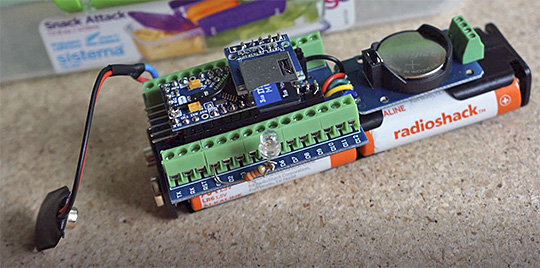
This is a build variation of the basic 3-Module logger described in the Cave Pearl Data Logger paper at Sensors. This configuration sleeps at 0.20 mA or less if you use an Arduino with an MCP1700 series regulator, so a 4xAA battery pack like the one shown should be good for more than a year. If the stacking shown in this tutorial looks a bit too complicated for your skill level, take a look at the EDU version from 2019 where all the parts are flattened out into a pre-made box. It’s quite a bit easier to assemble.
If you need a logger with a rugged waterproof housing, it’s still hard to beat the crimped-jumpers build released in 2016. However sometimes I just want a quick bare-bones unit for bookshelf test runs while I shake down a new sensor. I can whip up a breadboard combo in about twenty minutes, but they stop working if I bump one of the wires loose. I’ve lost SD cards from this half way through a long term test, and I’ve also run into issues with noise & resistance from those tiny breadboard contacts.
To address this I’ve come up with a new configuration that uses a screw-terminal expansion shield originally intended for the Nano. This requires a reasonable amount of soldering, and after some practice, between 2-3 hours to finish depending on how many “extras” you embed into the basic three component core. In return for that time you get all the pins broken out, making this approach almost as flexible as a breadboard, and much more physically robust. Pop them into some pre-made boxes and these little guys qualify as deploy-able for relatively stable environments (though I wouldn’t use those pre-made boxes outside unless I could pot everything inside that housing with paraffin wax)
Connection Diagram:

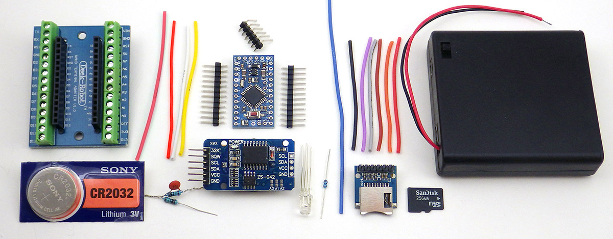
PARTS & MATERIALS
 |
|||||
|---|---|---|---|---|---|
| Bill of Materials: | $8.55 | ||||
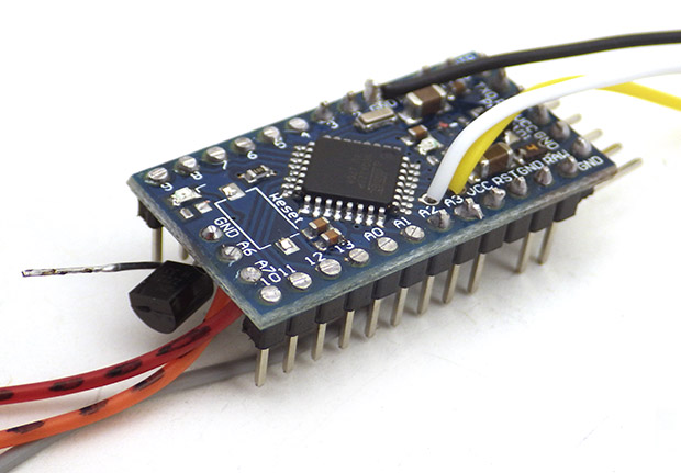
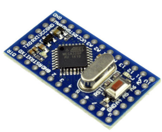
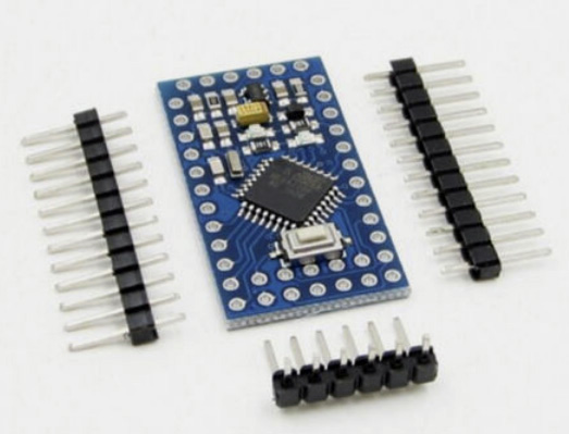
| Pro Mini Style clone 3.3v 8mHz I always get the ones with A6 & A7 broken out at the back edge of the board. |
$2.00 | ||||
| Nano V1.O Screw Terminal Expansion Board Note: To save time, you can spend an extra $1 for pre-assembled boards by Deek Robot, Keyes, & Gravitech. Note that bad vendors show photos of the pre-assembled boards in their listing, but then ship you the no-name assemble-it-yourself part kit. That kind of bait-n-switch tactic is very common with dodgy eBay suppliers. Or if you have a board with unusual dimensions, you could fabricate a custom screw terminal shield from scratch. |
$1.05 | ||||
| DS3231 IIC RTC with 4K AT24C32 EEprom (zs-042) Some ship with CR2032 batteries which will pop if you don’t disable the charging circuit! Also the DS3231N or DS3231SN chips are much better with ± 2-3ppm error, The DS3231M is a very different chip with ± 5ppm, so buy a small number from each vendor until you find out which chips they put on the module. |
$1.25 | ||||
| SPI Mini SD card Module for Arduino AVR Be sure to buy the ones with four ‘separate’ pull-up resistors! The second resistor from the bottom of these boards needs to be removed because it is pulling up the SCK pin, which with our SD driver needs to rest low because the SD card libs uses mode 0. I found the best results by removing the bottom 3 resistors, and then using the Arduino’s internal pull-ups on mosi & miso. |
$0.50 | ||||
| 4xAA 6V Switched Battery Holder The logger works with battery packs holding 3 to 8 AA batteries (with the default MIC5205 regulator). When using non-switched battery holders, I add Amass XT30U Bullet Connectors between the holder and the logger. |
$0.75 | ||||
| CR2032 lithium battery | $0.40 | ||||
| Sandisk or Nokia Micro SD card 256mb-512mb Older Sandisk & Nokia cards have lower sleep & write currents. They also are better suited to access via the SPI interface, while larger newer cards are not. Test used cards well before putting them in service. |
$2.00 | ||||
| Common Cathode Bright RGB LED 5mm ( & 30kΩ limit resistor) A brighter bulb lets you use a larger limit resistor for the same light output. |
$0.05 | ||||
| Double Sided Tape, 2x 10MΩ resistors, 28awg silicone wire, header pins, etc… | $0.50 | ||||
| Donation to Arduino.cc If you don’t use a ‘real’ Promini from Sparkfun to build your logger, you should at least consider sending a buck or two back to the mothership to keep the open source hardware movement going…so more cool stuff like this can happen! |
$1.00 | ||||
| Comment: You might need one of these to get started: (not included in the total above) | |||||
| 3.3V 5V FT232 Module ***Be sure to set the UART module jumpers to 3.3v before using it!*** and you will need a USB 2.0 A Male to Mini B cable. |
$2.75 | ||||
| Micro SD TF Flash Memory Card Reader Get several, as these things get lost easily. My preferred at the moment is the SanDisk MobileMate SD+ SDDR-103 which can usually be found on the ‘bay for ~$5. |
$1.00 | ||||
VIDEO GUIDE
In 2018, a visiting colleague inquired about the steps involved in building a Cave Pearl logger, and I figured the best way to convey that was to simply built one while they recorded the process. This took about three hours, and those videos are now available on YouTube. The order of operations in the videos is slightly different from the written instructions below, but the changes are relatively minor.
COMPONENT PREPARATION

Clean absolutely everything. I go over every surface of every module with 90% isopropyl alcohol and cotton swabs until those boards are squeaky clean. Then all the surfaces that I’m not soldering get a layer of conformal coating. (except the SD card spring contacts…) The pads I do solder get cleaned afterward to make sure there’s not one speck of circuit wrecking flux left, and then I coat those joins too. I usually get several years of continuous operation of these loggers, and I’m convinced it’s because I clean the parts thoroughly during the build process. Just as a reference, I recently took a look at the the ADXL345 module (pictured at right) inside my first drip sensor prototype which I built in 2014. Since it was just a bench prototype, the module did not go through my usual cleaning procedure, and it was never deployed. So this is what happens when uncleaned boards are simply left sitting on a bookshelf inside the house – just imagine what could happen to the parts you actually deploy in the field…

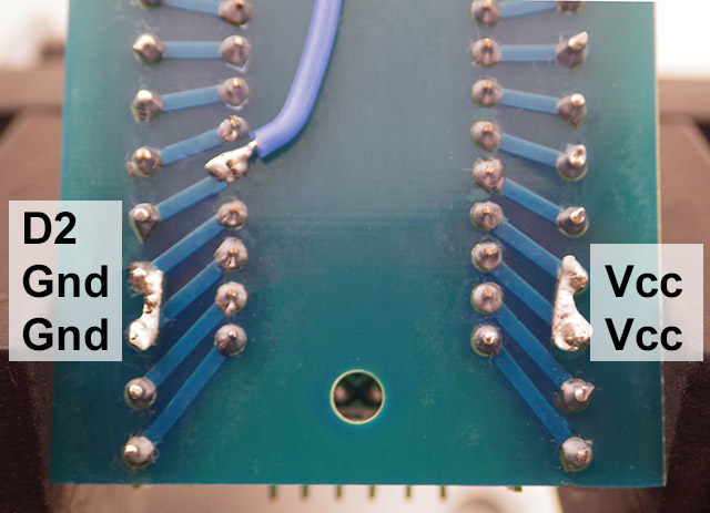
Bread-board your logger before soldering!
With the quality variation you typically see in these cheap parts, I make a pre-soldering breadboard version of each unique combination to confirm that the components in my build aren’t drawing excessive current – especially the SD cards! I bin between 10-20% of the low-end sensor modules I get from eBay, simply because they draw excessive power for no obvious reason, as compared to the others from the same batch…
(note: in the photo to the right D2 is hard wired via a jumper to the rtc SQW line – leaving an unused breadboard row which I’ve re-purposed to bridge vcc to the power rail on the opposite side of the board. And in this example, D4 provides GND for the indicator LED)
The Main Board:
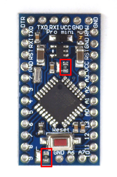
In this build the six serial UART I/O pins must have 90 degree angled headers to make more room for the RTC board which will sit on top of the main board later. Solder those header pins onto your Arduino board, and test it with your UART adapter. Generally speaking, about 10% of the cheap modules I buy from eBay are flakey in some way, and it’s quite annoying to discover that after you’ve assembled a logger. Once you know the board is working, remove the power and pin13 LED resistors. These limit resistors tend to move around from one manufacturer to the next, so you might have to hunting for them on your particular board. You also need to remove the RESET switch from the board, or that button will be compressed when you put the SD card adapter into place:
{Click any images to see larger versions.}
 |
 |
 |
Solder the side rows of straight header pins so that they project from the bottom of the board. I usually skip the two reset pins, so that I can re-purpose those screw terminals later as GND and Vcc (photo 3 below) but if your application needs reset functionality then solder those headers as normal. Add wires to the top of the board for the A4 (SDA white) & A5 (SCL yellow) lines of the I2C interface. Add wires to the A6 & A7 vias so that they project from the bottom of the board.
 |
 |
 |
Once all the pins are in place clean any flux residue from the board with 90% isopropyl alcohol and a cotton swab. The final step for the main board preparation is to trim the pin header solder points on the TOP of the board flush with the surface: D4-D9, D10-D13, and A0-A1. Then affix some double sided tape in place over those trimmed pins, which will mate with the bottom surface of the SD adapter.
 |
 |
The RTC Module:
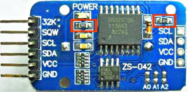
The simplest modification to these DS3231 RTC boards is to remove the charging circuit resistor and power LED limit resistor from the circuit board (indicated with the red squares in the first picture). LIR2032 rechargeable batteries are nominally 3.6v, and will not charge with this module connected to a 3.3v Arduino. Replacing that with a CR2032 will backup the RTC for many years of operation
 |
 |
 |
Add two layers of double sided foam tape, so that the thickness matches the top surface of the DS3231, and the inside edge aligns with that side of the chip. These two surfaces will mate with tape on the SD adapter board.
Since the RTC board already has 4.7k pullups on the SDA (data) and SCL (clock) lines, you will not need to add them to your I2C sensors. This board also has a 4.7k pullup on the SQW alarm line. We will be connecting SDA, SCL, GND and VCC wires to the small cascade port on the module.
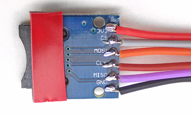
The SD Card Adapter:
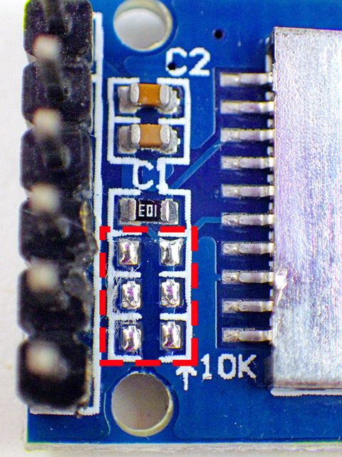
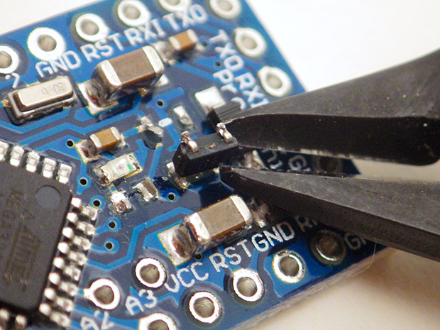
This SD card adapter comes with small surface mount pullup resistors on the MOSI, MISO & SCK (clock) lines (removed from the dashed red line area photo 2 below). The Arduino SDfat library uses SPI mode 0 communication, which sets the SCK line low when the logger is sleeping. This would cause a constant drain (~0.33mA) through the 10K SCK pullup on the module if we did not remove it. I prefer to pull MOSI & MISO high using the internal pullups on the 328P processor, so those physical resistors on the breakout board can also be removed. But be careful to leave the top-most resistor of the four in place to pull up the DAT1 & DAT2 lines. This keeps those unused pins on the μSD card from floating when the cards are accessed in SPI mode.
 |
 |
 |
Add jumper wires to each of the headers pins on the bottom of the SD adapter and trim those solder joints till they have a relatively low profile . Then cut away the vertical header pins from the top of the board. Place a strip of double sided tape on the bottom of the SD card module opposite the soldered wires. This strip acts as a spacer to level the SD board when it is placed in contact with on the double sided tape on the mini style Arduino board.
| The SPI connections: RED: 3.3v regulated Grey: Cable select (to D10) Orange: MOSI (to D11) Brown: SClocK (to D13) Purple: MISO (to D12) BLACK: Ground |
 |
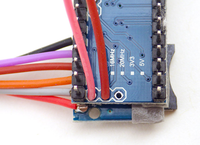
The Screw Terminal board:
These screw terminal boards are designed for use with Arduino Nano boards, but if you orient the two correctly when you connect them, labels on one side of the shield will be in alignment with promini pins:

Drilling a pass-through hole lets you bring the jumpers down to those unused pins, and to make other connections to solder points on the underside of the shield without blocking the M3 mounting holes. It is also possible to fabricate your own terminal board.
ASSEMBLING THE LOGGER PLATFORM
Attach SD adapter to the Pro mini:
The first step is to attach the SD adapter to the board, but this must be done with a slight overhang, so that at least the red Vcc wire on the SD adapter extends beyond the top surface of the pro-mini board. It’s OK to leave more overhang than I’ve shown here, but if you leave less, the wires on the RTC cascade port might interfere with access to the serial I/O pins.
 |
 |
 |
Place a strip of double sided tape across the SD adapter board as shown, taking care not to cover the hole showing the card lock spring. When that tape is in place, bring the ground and Vcc lines from the SD board forward and make a gap in wire insulation so you can splice-solder them to the GND & Vcc pins on top of the pro mini board. This procedure simultaneously connects the rails to the SD adapter, and brings power to the I2C cascade port on the RTC module.
 |
 |
 |
 |
 |
 |
Connect the RTC board:
I recommend that you take a bit of time holding the RTC board in place over the SD & mini combination while the protective covering is still on the tape, so that you get a feel for the alignment before you actually try to stick these parts together. With the cascade port oriented towards the Arduino’s serial I/O pins, the topography of the SD adapter fits snugly into place against the DS3231 chip on the RTC module.
 |
 |
 |
After you stick the pieces together, trim and solder the I2C bus wires to the RTC’s cascade port. Note that it is possible to unstick the parts afterwards by gently levering them apart with a screw driver, but be careful you don’t rip the metal shield off of the SD card adapter in the process.
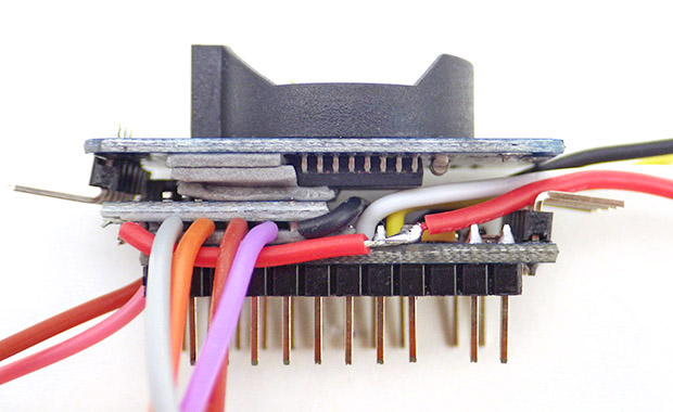
Attach everything to the Screw Terminal Shield:
If you’ve gotten this far, then you can now relax, because all the tricky stuff is done. Trim and tin the four SD lines and bring the down to the D10-13 SPI screw terminals just below. Note that D12(MISO) & D13(SCLK) lines must crossover. Bend the pins on the RTC board downward and solder jumpers onto all but the 32K output line.
 |
 |
 |
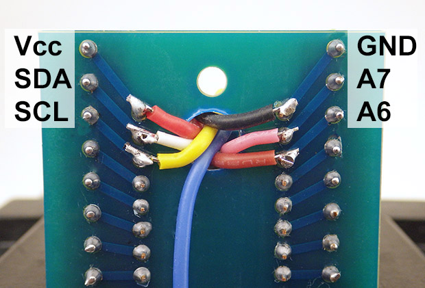
Pass the SQW alarm line (in blue) through the hole and solder it to the D2 pin projecting from the underside of the terminal adapter board. If you left out the reset pins when initially soldering the headers, bridge those unconnected terminal screws to the adjacent Vcc & GND lines. Then patch A6/A7, and the four I2C lines from the RTC board to the unused pins at the end of the screw-terminal shield. I generally run these loggers on 3xAA battery packs with a 2x10M ohm voltage divider providing 1/2 of that battery voltage to A0. So the last step is to add that voltage divider, along with some extra tape to serve as foot pads.
 |
 |
 |
The battery voltage calculation for a divider with equal value resistors is: float batteryVoltage = float((analogRead(A0)/ 511.5)*3.3); But the MIC5205 regulator found on most promini style boards will accept anything between 3.4 to 12v input, so you will need size your resistors to convert the peak battery pack voltage into something below the 3.3v aref limit. To cover that whole range, you’d need a pair that puts 1/4 of the battery voltage on A0, and a R1(high side) = 3*R2(low side) combination would do that, changing the 511.5 constant in the equation above to 255.75 With 5205’s dropout potentially rising to 300mV during 200mA SD writes, I usually shut down the loggers when the main battery falls below 3.75 volts. With Meg-ohm size resistors, I leave that divider connected all the time, but there is a wonderful self-disconnecting voltage divider idea over at JeeLabs for those who want to use smaller resistance dividers. Also keep in mind that resistors you get off of eBay are usually +- 5% (no matter what the vendor claims) which can really throw off your battery readings: ALWAYS measure high value resistors with a good quality DVM before making a divider with them. And with resistances in the megohms environmental contamination such as skin oils, soldering flux residue, etc. can easily reduce the effective resistance in time-varying ways.
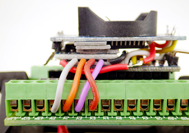
As we removed the pin13 LED back at the start, solder a limit resistor onto the ground of a common cathode RGB and connect that to one of the ground connections, with the other legs going to D4R-D5G-D6B. I usually add a few labels to keep track of the extra terminal connections, and any re-allocated any pins for a specific build. Unfortunately black sharpie marker doesn’t stick to those green terminal shrouds very well.
 |
 |
In this example I’ve re-allocated the screw terminals that would normally have been connected to the two reset pins, but you could use under-board wires to re-assign any of the terminals in a similar fashion. For example, if your application will not be using the RX/TX pair, those could be turned into extra Ground or Vcc points. I’ve never understood why the pro-mini design breaks out reset twice but leaves the Aref pin hidden, so adding a wire to the little aref stabilizing cap would let you fix that issue.
Your Logger is ready to go!
As this is simply a different physical arrangement of the same core components, you can follow the logger testing procedures described at the end of the 2016 Dupont Jumper Build , which also provides links to a basic data logger script to help you get started on your project. For the build described above, the pro-mini’s MIC5205 regulator delivers sleep currents less than 0.25mA (Promini~0.05mA, sleeping SDcard~0.05-0.09mA & RTC~0.09mA)
That should should reach a year of operation on 4xAA’s.
While it took me a day to get the first one of these sorted, the second one took less than three hours, and the third took less than 2 hours. I lost count after that, and now these things seem to be multiplying like tribbles. If you need unobstructed access to the SPI bus, you can move the SD lines to under-side solder connections as we did for the I2C bus. This also makes the logger a little prettier, but since I’m usually making these in a hurry, I often leave those wires on the surface.

The photos in this series were made with Adafruits 26AWG silicone wire, but if you are adding more bottom-side connections, switch to smaller diameter 28AWG wire, or make the pass-through hole a bit larger to accommodate the extra lines. Switching the 90° I/O header pins to the bottom of the promini board gives you more room for the RTC wiring.
 You can make the component stack more rigid by adding a few strategically placed beads of epoxy putty. In fact you could hold the whole thing together that way, so long as you take care not to bridge any contacts – especially where the DS3231 header pins are near the metal top of the SD adapter. Also keep in mind that the putty sets rock hard in about five minutes, so if you make a mistake with that assembly method then you’ve bricked the unit – so test all your connections before this last step!

If you are careful about placement of the batteries, you can fit this new screw-terminal design onto the abs knockout plugs that I’ve been using as mounting platforms. This means that you can still fit the logger into the inexpensive 4″ housings
that I outlined for earlier builds with room under the platform for a second battery bank if needed. Given how often makers need to put a shell around their projects, I’m surprised that no one has taken the old B-Squares idea into three dimensions to create a re-configurable snap-together housing system. These videos from the tutorial set walk you through the method we developed in 2016 to build housings from PVC plumbing parts that are robust enough for real world deployments:
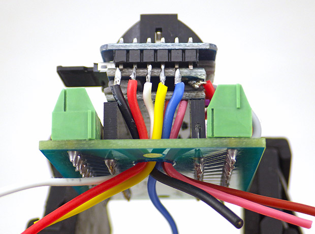
Battery Platform & Sensor Connections
In addition to the I2C bus, I’ve started breaking out A0-A3, rather than digital lines, since those A ports can do double duty as either analog or digital I/O with some code-side settings. With screw-terminals on all lines anyway, I only break those out to connectors for quick sensor swaps in the field.
Potting Sensors & Waterproof Housing Pass-Through Connections
One thing to keep in mind for any project built from eBay parts is that most of those boards use cheap Y5V capacitors; which have terrible temp-coefficients compared to X7R/NPO’s. So you need to test your project extensively if you want it to operate over a wide temperature range. My home freezer tests to date have been running ok, but I’m not relying on the Pro Mini’s oscillator/clock for anything that is timing-critical. I do expect to see bus timing drift out of spec at the low temperatures. For loggers built with I2C sensors, stick with 100kHz for your first few builds, then things “just work every time”…75% of the time. The 1.1v internal band-gap also changes significantly with temperature, so if you use it as Aref, expect to see the readings go up, as the temperature goes down.
Addendum 2017-06-21:
I’ve been on a steep learning curve since the beginning of this project, and you don’t have to dig very far to find stuff on this blog that seemed like a good idea at the time, but later turned out to be completely wrong. I should write some sort of disclaimer, but instead I’ll pass along a recent forum comment that summarizes the kind of criticism we’ve been getting lately:
“In the old days, an embedded enthusiast would have designed the thing (and think AVR) from the outset to meet objectives / specs, not struggle with integrating the various modules and meeting very-so-so sleep currents (while thinking Arduino). Surely, this is a textbook example of how not to do embedded engineering if you are doing it for a salary.”
It’s good to have someone rattle your cage once and a while, and I’ll admit they have a valid point. ( In addition to the fact that I’m not an engineer, and I don’t get paid…) People complain like that about the pitfalls of using modules & libraries all the time, but the thing I like about the Arduino platform is that you don’t have to know everything before you can do anything. I’m just figuring it out as I go along.
Still, an affront like that demands some kind of response. So to defend the honor of my fellow Arduino Kool-Aid drinkers, let’s look at how you might tweak those modules to improve this loggers sleep current performance:
1) Pin Power the RTC:
These DS3231 boards don’t get a lot of love because they have about the worst battery charging circuit ever devised, and an equally useless LED power indicator. But for less than a buck delivered to my door, these boards are considerably cheaper than the raw components they carry: so yeah, I’m going to look under that rock and see what I find. That charger can be disabled with a simple flick of the soldering iron, and at this point we have years of successful run time using a non rechargeable CR2032.
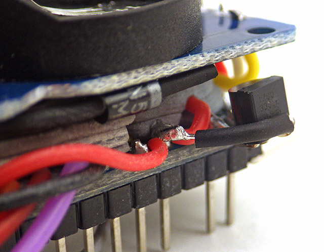
More interesting is the fact that on a 3.3v system, you can leave the charger in place, cut the Vbat line at the battery terminal, and patch in a 1N4148 diode to match the one already on the module. After the CR2032 burns down a bit the two circuits balance out, and the main battery then takes over supplying the 3µA timekeeping current:
This mod cuts your loggers sleep current by about 0.09 mA. Keep in mind that this only works because the RTC was designed for a controlled switch over to the backup power circuit. In general, de-powering I2C devices is not a good idea because the pullup resistors keep the SDA and SCL lines high. When a regular I2C connected chip has no power, you could leak current via SDA and SCL through the I2C device to GND.
2) Buffer your data before saving:
Those DS3231 RTC modules also have a 4K EEprom on the board, and that lets me save data in 32byte page-writes with reasonably simple code. While the I2C bus is dead dog slow by embedded system standards, you can hang oodles of things off those wires without worrying about cable select lines, or some gummy protocol weirdness. For an extra buck, you can add 32K more memory without any significant changes to your Arduino script. That usually buffers about a week’s worth of data before I need to save to the SD, even though I’m still making the unforgivable programming sin of storing everything in ASCII string variables
 |
 |
 |
Small red-board versions of the AT24C256 tuck nicely into the 12mm gap between the headers, but you could just as easily put an I2C sensor into that space. If you get boards with the address pins broken out (the one above doesn’t), you can connect up to four of these eeproms to the same logger. A side benefit is that the 32K eeproms are rated to 400kHz, while the 4k’s are only 100kHz, so the upgrade also lets you accelerate the I2C bus clock, since the DS3231 is also rated for 400kHz.

This DIP-8 carrier module lets you configure up to eight I2C addresses, or you can roll your own.
Even larger eeproms are available in the code compatible AT series, but the wire library limits you to writes smaller than their page sizes. If I had the chops, the path to an IC-only logger is obvious. The AT24C512 is pin-compatible with the SOIC family that includes the 32k AT24C256 and the AT24C32. So you could also just replace the 4k eeprom that comes with the RTC module with that 64k chip possibly taking it all the way up to the 128k AT24C1024.

One thing to watch out for with some eeproms like the 24LC512: “When doing a write of less than 128 bytes, the data in the rest of the page is refreshed along with the data bytes being written. This will force the entire page to endure a write cycle, for this reason endurance is specified per page.” So it’s worth the time to buffer your data until you can do a page write with some eeproms. AT24C512’s have the same 128-byte Page size with 16-bit addressing , but partial page writes are allowed. With most larger eeproms you also need to send ‘block addresses’ in addition to memory locations during a save event.
I’d love to switch over to superfast Fram chips, but Adafruits module lists a very high standby current of 27uA, while most eeproms sleep between readings at about 1uA. In a data logging application that kind of power use between cycles removes the benefit of the faster data-saving. However if I was working with really fast data inputs, I’d consider Fram for something like a ramdisk. Paul Stoffregen’s SerialFlash library is another interesting option, as it allows one to write data to an SPI Flash memory chip with a filesystem-like interface similar that on an SD card.
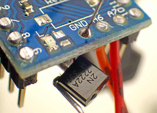
3) Cut power to the SD card:
The Promini clones I’m using have a tap at the back that is conveniently located for ground side switching of the SD cards. This lets me tuck a 2N2222A under the board with that extra eeprom. Cards hit the regulator pretty hard when they initialize, causing significant voltage drops, and if you find that your unit is not saving properly with this technique it’s probably because those transient lows are causing restarts. I usually add caps to provide and extra 30μF on the rails to help handle those spikes, and I may bump that even higher for cold climate deployments since cheap ceramic caps have terrible temperature constants. Older Nokia 256 & 512 Mb SD cards have significantly lower writing currents than modern SD cards – often holding between the 50-75 mA range during init.
 |
 |
 |
 |
 |
Code and information about this technique are described in some detail on the
SD power post This is a relatively high risk strategy, but it can cut your sleep current by another 0.1mA. (Note that while the BJT shown above works fine, on more recent builds I’ve switched to the Supertex TN0702 mosfet for ground side switching with 3.3v logic)
4) Replace the voltage regulator:
The MIC5205 on those pro-mini clones is not very efficient at low power (~10-20%), so replacing that with an MCP1702-3302E/TO can cut your remaining sleep current by more than 50%. The 10uF caps from the original reg. are still in place on the board, so this upgrade has been working fine with the 1700 just hanging off one side. Also keep an eye on the dropout voltage, which on the MCP1700 series can rise as high as 600mv if you push them to their 250mA maximum – many SD cards will pull up to 200mA for brief periods. This requires a fairly high input cutoff around 4v.
 |
 |
 |
If soldering in close quarters like this gives you the heebie jeebies, you can dead-bug the reg & voltage divider onto the battery connector like I did for the 2016 builds. Alternatively you can simply build your logger around a small form-factor boards that already have an MCP1700 series regulator, such as the Rocket Scream Mini Ultra or the Moteino. The HT7333-A is a less expensive TO-92 LDO regulator with similar specs (250mA max out).
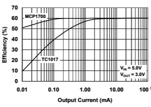
AN1025 FIG 2: Efficiency % ~= VOUT / VIN
All linear regulators (including LDO’s) are less efficient as the raw input voltage increases. (So a 4xAA 6v battery supplying a 3.3v rail system will be about 55% efficient under load) For higher drain processors sometimes people use buck converters (typically 90% or better efficiency) to step down higher input voltages, and then feed that ripply output into an LDO to smooth it out for delicate components. But switching regulators often fall down to 20% efficiency or less at the low micro-amp sleep currents you see with dataloggers, while the MCP1700 keeps chugging along at around 50% until your load approaches its 1.6μA quiescent current.
(Note: that the pin maps are different for each board, so you might need to adapt the wiring connections shown in the information above. Also keep an eye out for fake LDO regulators with high dropout voltages. If you’re not sure what you’ve received, bump the input voltage cut-off to at least 1v. The Promini’s 10uf tantalum caps should be enough to damp oscillations, but it probably wouldn’t hurt to add another on the output for extra stability)
And the result?

This optimised logger is drawing less than 0.02mA sleep current with a MS5803 pressure sensor in tow. That’s 5x more than you’d see from a raw 328p, but not bad considering that we built a fully functional data logger out of 99¢ eBay modules. (Note: with the default MIC5205 reg. in place, the same logger would draw ~0.055mA)
These modifications to the basic build plan probably violate some important electrical engineering rules, and I can almost guarantee that nothing will work properly the first time you try it. But don’t let the fact that you might destroy a few cheap components along the way prevent you from just going for it. Although it might be best if you don’t show your project to any engineer friends at the beginning… unless they’re working on a new textbook 🙂
Addendum 2017-12-22: Low sleep current the easy way with a TPL5110
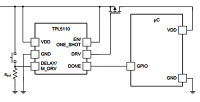
Lady Ada demonstrates their new board HERE. and cfastie has been wiring up his own breakout boards at PublicLab.org
It can take a bit of Kung-Fu to implement the power optimization methods described this post, and if you haven’t quite reached that level the Adafruit TPL5110 Low Power Timer can bring any 3.3v logger down to ~0.02mA for a fiver. Cfastie has is putting this board through it’s paces over at PublicLab.org It’s too bad the TPL5110 timer IC can’t tolerate more than 5.5 volts, because it would be a god-send for all those UNO based loggers out there, but their minimum input is ~6v.
The only problem I can see with the TPL5110 is that you don’t have precise control over the sleep interval [Timer accuracy 1% (typ)], and temporal inconsistency becomes important for many kinds of analysis on time series data over long periods. Since the sleep currents I’m seen now are already in the 20uA range, I probably will not bother with full power-down methods till I start needing to run on tiny batteries. But when I do get there I will probably use the DS3231 RTC alarm (which outputs low) to control a P-channel Mosfet on the high side of the main battery supply. The trick is finding a mosfet with a low enough gate voltage, so that it will be fully turned off till the RTC alarm fires ( AO3401? ). When the SQW alarm goes low, it turns the p-mosfet on and powers everything including the mcu board which would then get to work taking samples and storing data. The final step after everything is done would be to re-program the next RTC alarm, and then write zeros to the alarm flag registers (A1F and/or A2F) which would release the SQW line on the gate of the mosfet. (+ you would need a pullup resistor on the gate to make sure the pFet turned off properly – but that’s just a pullup and could be quite large- in the Meg ohm range). The RTC itself would run off a coin cell, and DS3231 RTC will generate such alarms when running on backup power. Kevin Darrah talks about a slightly more advanced latching kill switch approach that could also be adapted.
My biggest concern about kill switches is that the SD card can be corrupted if power is immediately removed during numerous conditions, so you need to make sure you can safely shut down after buffering all your persistent variables in the eeprom. Most Arduinos will boot in less than a second, but capturing rapidly occurring events like the sensor interrupts we use for our cave drip counters would be nearly impossible.
Addendum 2018-02-13:
 Brian Davis (another builder who tortures his loggers in caves) passed on a neat idea for using Pro Minis with Nano screw-terminal shields. Simply add male pin headers beyond the edge of the board, and then solder the A4/A5 and A6/A7 connections to the top of those pins. Then pull Vcc from the UART connector. If you run the SQW alarm wire over the top to D2, you no longer need to drill a hole in the shield to bring wires down to the bottom of the board like I did, and you can still pull the Pro Mini out of the adapter board later if you have to.
 An alternative hack that may be useful to people wanting to break out those pesky offset A4 & A5 pins would be to jump them over to re-purposed A2&3 pins, which you make available with a couple of trace cuts. Of course this reduces the number analog input lines on your logger, so it’s not quite as functional as Brian’s extended headers.
Addendum 2018-05-23:
Well Brian’s been at it again, coming up with more alternative build ideas:

Another benefit of the screw-terminal board is that you can connect the assembly to a 2″ test cap by simply looping a zip tie through one of the mounting holes.
Both of us are working with the limitations of a 2″ housing tube, and using the battery holder as a mounting bracket is a great solution. I also like the addition of the screw terminals on the RTC’s cascade port (Sparkfuns Quic adapter board is also a pin-matched option there if you are using their sensors ) For the Pearls, we wire the DS3231 in the opposite direction, and we have some high drain multi-sensor builds that require ganged battery packs to go the distance. So for us it makes sense to stick with the ‘stacked sandwich’ arrangement, with the batteries in completely separate containers. With high temperature variations, and long duration deployments, we also see a fair number of battery leaks. This ruins the terminals forcing us to replace the packs more often than we’d like.
Even so, I’m utterly thrilled to see these creative ideas coming out of the logger building community, as that will ultimately give the open science hardware movement some real legs. And while we are on the topic of build variations, it’s worth noting that there are a host of Pro-Mini style board variations out there that may help with these part re-arrangements:
 |
 |
 |
| A4 to A7 on back row | Analog & SPI on the back row(s) Julian Illet uses these in his ammeter build. |
328PB = two hardware SPI serial ports though I’ve had success with software SPI on the analog lines to drive displays. |
I’ve been using the more common variant with GND-A6-A7 on the back row as I bring the I2C lines forward to connect the RTC, but I can see how having those offset pins at the back row could make soldering easier for some builds.
Addendum 2020-04-05: New Underwater Housings for the Screw Terminal Stack

Happy to present the 2020 iteration of our DIY submersible housings, with fewer PVC parts & faster assembly. Using the power mods described above, with the screw terminal stack, reduced the need for batteries & the space they required. With a double 332 o-ring this build is not quite as robust as the original ‘long body’ version described in the 2018 paper, but it still should get to about 10m. Can’t wait to see the first student builds based on this design make it into the wild later this year.

Do you have any schematics?
The schematic for the basic build is the same as the previous years so I did not reproduce it in this post:
https://edwardmallon.files.wordpress.com/2015/10/thebasicdatalogger_1500pxw.jpg
but the enhancements are not included in that, because I figured that people could pick and choose which ever one they felt like implementing. I also did not want to encourage people too much with the SD card shutdown, as there is some risk to your data with that strategy. The basic build is really solid, and I’m just retiring basic 2014 units out of the fleet now because of the relatively high sleep current..but they are still running!
hi how many sensor are you able to add to this datalogger? is the script in previous version functional in this new version?
Since the RTC is an I2C device, the support for that protocol is built-in to the basic script by including the Wire.h library (and there is an I2C hardware peripheral built into the arduino’s 328p processor). In theory you can add up to 128 I2C devices to the bus, though in practice I’d be surprised if you got past 5 or 6 before running into issues with pullup/bus capacitance, etc. With A6/A7 broken out to the screw terminals, you have five analog lines available for sensors, since I generally use A0 for the main battery monitoring voltage divider.
All of the different pro-mini based logger builds are variations of the same basic wiring schematic, and will run the same code. Of course if you add things like oversampling, powering the RTC from a digital pin, or cutting power to the SD card, you will have to adapt the basic scripts for that.
I’d like to add a temperature sensor. The goal being to record temperatures when temperature sensitive medicine is shipped from CA to AK. I poked around on the site, but didn’t really see a straight forward explanation of how to create and connect a temperature sensor. I haven’t looked at the code yet, so I guess some hints could be found there. Any guidance would be helpful.
OK. I kept poking around on the site and found the reference to the adafruit temperature sensors. I think there will be enough information for me to succeed in adding them. Thanks for putting this information out there.
I’m glad you found the Adafruit MCP9808 references as that sensor offers excellent accuracy; something often overlooked in the hobbyist market which focuses too much on resolution. We always recommend that beginners start with I2C sensors when using this logger, because it is so easy to find good libraries to support them at Sparkfun, Adafruit, Pololu, etc. And the sensor simply gets connected in parallel on the same 4 wires as the RTC module.
Add your sensor’s library to the basic logger script posted on Github with an #include sensorlibrary.h statement at the beginning of the code. Take a sensor reading (usually described by a tutorial from the vendor who wrote the library) and then add two lines to the dataString concatenation steps:
dataString += “, “; //puts a comma between the two bits of data
dataString = dataString + String(YourSensorReadingVariable);
At that point the sensor readings should be saved to the SD card. Change the sleep interval in that code to one of 1, 2,3 5, 10,15 or 30 minutes, and you are ready to start logging!
Thanks so much for the added info. It will be very helpful in getting things going. I just ordered the parts so they will be here sometime in the next month. Guess I can start working on the toolchain to put together the libraries as suggested above while I’m waiting!
I already have the Arduino IDE installed and working (used it for a CNC machine and RC model receivers), so I don’t really think I have too much more to do.
Thanks for your advice.
The temperature sensor I have is https://learn.adafruit.com/tmp36-temperature-sensor/using-a-temp-sensor and from what I’m seeing, I would just need to modify the logging script to accommodate the analog port I plug it into.
Additionally, am I right in saying if I don’t want to measure the voltage, etc (my project has a very limited time duration, less than a month), I can eliminate the voltage divider that is connected to A0 in your design?
Thanks for your advice.
Yes you could get rid of the voltage divider monitoring the main battery voltage, but I’d advise against it. Changes to the rate of battery discharge are exceedingly useful for pinpointing when something is going wrong with a logger, because that usually introduces a dramatic change in the angle of the main battery discharge curve.
However if you are leaving the Vbat divider out, you could simply connect the TMP36 to the A0 line since that’s already being read in the code. Just change the math in the readBattery() function that converts the raw readings into the battery voltage, into calculations appropriate to the TMP36.
Alternatively, –include– a sensor library for the TMP and simply read the sensors output into its own variable at the start of the main loop. Then add that variable to the print functions: following the same pattern used for the other sensor reading variables.
When plugging in the battery to the RTC, and measuring voltage on VCC to GND on that module, there is no power. That doesn’t seem right to me. Also, I wondered if I really needed that module since I won’t have any I2C sensors on this particular logger.
The backup coin cell is supposed to power ONLY the RTC chip, and is connected to the Vbat pin. You can see a schematic of the board over at my page on these RTC modules . If the coin cell voltage showed up on Vcc, it would mean that the coin cell was supplying power for all the devices on the logger…
The RTC’s primary function is to wake the logger from sleep, and then to provide a time stamp with the sensor readings. If your application does not need either of those things, then you can leave it out. Many logger projects that run for relatively short periods of time (ie 1-5 days) use the internal clocks on the 328P microprocessor. The problem is that these timers have thermal drift issues that accumulate over long periods. We run our loggers for > 1year so we have to rely on an RTC chip like the DS3231 to keep accurate time.
I just realized that I have a 168P instead of a 328p arduino. Any chance to make the code work on the 168 (it compiles, but is too big)?
In the meantime, I’ll have to purchase a 328p instead.
The basic starter code for the UNO logger tutorial that we posted on github. is about the smallest data logger script you are likely to find. It lacks the eeprom buffering, and other power saving features of the more advanced logger code, but it should still run >5 months on a pro-mini based build. It’s only about 100 lines, and you should be able to see where to make edits to accommodate your sensors. That script uses libraries for the RTC and the Sleep function – so you could save some memory by finding leaner code for those functions. Nick Gammon has good examples of sleep code at his forum, and you will find example Arduino code for the DS3231 in multiple places on the web.
Beyond that I’d look for examples using the ATtiny, people developing for those chips are operating under extreme memory limitations.
Hi, I have been working on a temperature and a Humidity logger.
I want it to last atleast 4 days, but currently it’s only lasting for, 6 hrs.
I have already worked on the sleeping part of the Code, works perfectly, until I switch off, the SDcard module and try to turn it on.
Modifying my Code to accumulate, the code for sd shutdown has proven quite difficult, since, I don’t have much time on my hands.
Can you please assist me on how to organise the Sdcard off and On code.
I was working using the code in this website here:. https://thecavepearlproject.org/2017/05/21/switching-off-sd-cards-for-low-power-data-logging/
NOTE: Am a beginner in Arduino Programming
If you are a beginner at programming, my honest advice is don’t mess around with SD card shutdown. The firmware in the card controller introduces too many unknown timing & power factors to deal with. Most of the older 256MB – 512MB sd cards automatically sleep around 0.07mA or less whenever there is no clock signal on the SPI lines. In that range you should be able to get more than a year on 3xAA batteries (in fact most of my loggers that simply sleep the SD cards run around 2 years) simply using the Rocket scream lowpower sleep library to sleep the Arduino board, & putting the sensors into their respective sleep modes between readings (you will need support libraries that give you the option of sleeping the sensor between readings). Those two things are much more important for longer run time than SD card sleeping.