

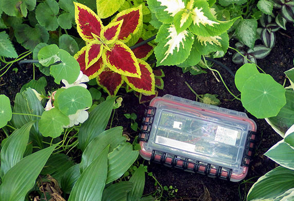
A $1.50 soil moisture sensor: ready to deploy. My first experiments with the pulsed output hack didn’t quite work due to probe polarization at low frequencies…but I’m still noodling with it.
There’s something of a cultural divide between the OpAmp/555 crowd and Arduino users. I think that goes some way to explaining the number of crummy sensor modules in the hobbyist market: engineers probably assume that anyone playing in the Arduino sandbox can’t handle anything beyond analogRead(). So it’s not unusual to find cheap IC sensor modules with cool features simply grounded out, because how many ‘duino users could config those registers anyway – right?
Legit suppliers like Adafruit do a much better job in that regard, but our project rarely uses their sensors because they are often festooned with regulators, level shifters, and other ‘user-friendly’ elements that push the sleep current out of our power budget. Sparkfun boards usually have leaner trim, but with all the cheap PCB services available now I’m tempted to just roll my own. Thing is, I keep running into the problem that in ‘prototype quantities’ the individual sub-components often cost more than complete modules with the reflow already done – and that’s before everything gets sand-bagged with shipping charges larger than the rest of the project combined.
So we still use a lot of eBay modules – after removing the usual load of redundant pullups and those ubiquitous 662k regulators. Once you go down that rabbit hole you discover a surprising number of those cheap boards can be improved with ‘other’ alterations. The reward can be substantial, with our low power RTC mod bringing $1 DS3231 modules from ~0.1 mA down to less than 3µA sleep current – which is quite useful if you want to power the entire logger from a coin cell.
Another easily modified board is the soil moisture probe I flagged in the electrical conductivity post:

Schematic before conversion: (regulator not shown). The output frequency is controlled by the time constant when charging/discharging C3 through R2/R3. Gadget Reboot gives a good overview of how the basic configuration works, feeding the RC filtered 555 output into a simple peak detector. Older NE555 based probes run at 370khz but the V1.2 probes with the TLC555 run at a higher 1.5Mhz frequency with a 34% duty cycle. It’s worth noting that dissolved salts, etc affect soil moisture readings until you reach the 20-30MHz range.
These sensors use coplanar traces to filter high frequency output from a 555 oscillator, but you’re lucky to see a range of more than 400 raw counts reading that filtered output with Arduino’s 10-bit ADC. On 3.3v systems, you can remove the regulator and combine the sensor with an ADS1115 for 15-bit resolution. I found you can’t push that combination past the ±4.096V gain setting or the 1115’s low input impedance starts draining the output capacitor. But that still gives you a working range of several thousand counts as long as you remember that the ADS1115 uses an internal vRef – so you also need to monitor the voltage supplied to the sensor to correct for battery variation. Trying to read the sensors output with my EX330 when the sensor was running brought the output voltage down by about 0.33v and it’s got 10MΩ internal impedance similar to the ADS – so a cheaper voltmeter will knock the output from this sensor around even more. Differential readings can reduce this problem because that doubles the ADC’s impedance.
Analog mode works well with long cable runs and piping that through an ADS1115 lets you communicate with three soil sensors over I2C if you are low on ports. And up to four of those $1 ADC could be hung off the same bus – though I’ve learned the hard way not to put too many sensors on one logger because it risks more data loss if you have a point failure due to battery leaks, critters, or vandalism. It only takes a couple of hours to build another logger for each set anyway.
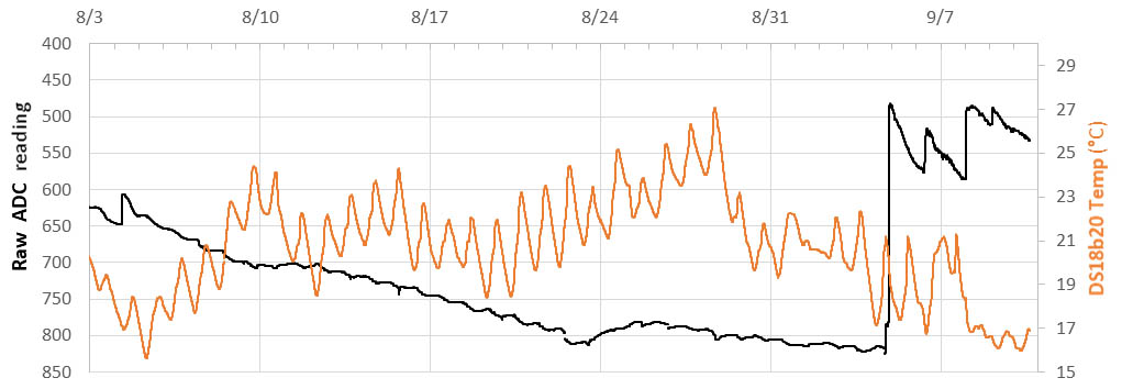
3.3v ProMini ADC readings from an analog soil moisture sensor at ~8cm depth (vertical insertion) with DS18b20 temp from the same depth. We ran several of these sensors in our back yard this summer. This segment shows daily drawdown by vegetation during the hottest/driest month of the year – followed by several rainfall events starting on 9/4 . This logger was running unregulated from 2x lithium AA cells and the regulator was also removed from the soil sensor. Aref moves in step with the supply voltage so we didn’t have interference from battery variation. C5&6 were removed from the board and the sensor was powered from a digital pin with 8 seconds to stabilize ( probably more time than needed). This humble sensor was less affected by daily temperature cycles than I was expecting but if you use ‘field capacity’ as your starting point the delta was only ~200 raw ADC counts. I manually watered the garden on 8/23 & 8/24 to keep the flowers from dying; but it was only a brief sprinkle. We have 6 months of continuous operation on these probes so far but with only that thin ink-mask protecting the copper traces I’d be surprised if they go more than a year. Even with epoxy encapsulating the 555 circuit, small rocks could easily scratch the probe surface on insertion leading to accelerated corrosion.
These things are cheap enough that I’ve started noodling around with them for other tasks like measuring water level. With a water/air dielectric difference of about 80:1 even unmodified soil probes do that job well if you put in a little calibration time. When powered at 3.3v, the default config outputs a range of ~3.0v dry to 1.5v fully submerged in water. So Arduino’s 10-bit ADC gives you decent resolution over the probes 10cm length. And since the TL555 doesn’t draw more than 5mA (after settling), you can supply it from a digital I/O pin to save power – provided you give the sensor a couple of seconds to charge the output capacitor after power on. Adding 120-150Ω in series to throttle capacitor inrush still leaves you with ~1.2v air/water delta. The sensors I tested stabilize at power on after ~1 second but take more than 35 seconds to ‘discharge’ down if you suddenly move the probe from air to water – this behavior indicates the boards are missing the R4 ground connection. (Note: After checking batches from MANY different suppliers I’ve now started adding a 1Meg ohm resistor across the output of any sensors that output ~95% of their supply voltage in ‘free air’. Sensors with the 1meg already connected the way it’s supposed to be on the board usually output ~85% of their supply voltage with the sensor in air & about 35% of their supply when completely submerged in water.)
A quick search reveals plenty of approaches to making the sensor ready for the real world, but we’ve had success hardening different types of sensor modules with a epoxy + heat-shrink method that lets you inspect the circuits over time:
Cable & Epoxy Mounting: (click images to enlarge)
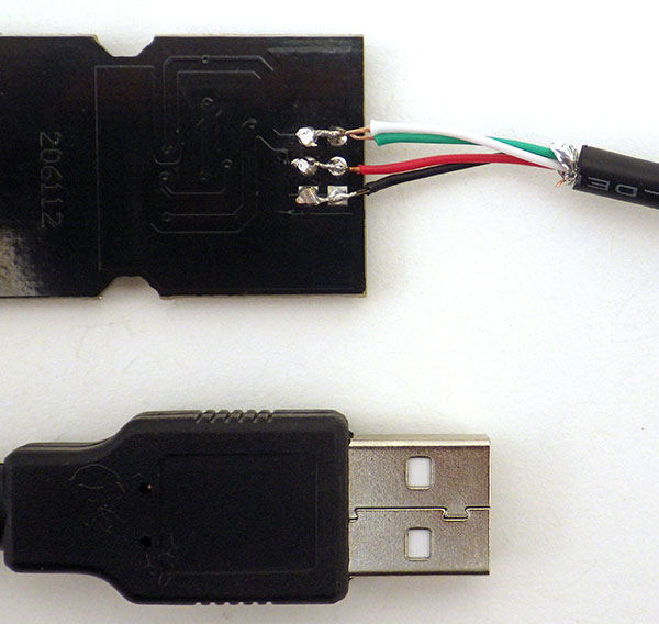 Clean the sensor with 90% isopropyl alcohol. An old USB or phone cable works for light – duty sensor applications. Here I’ve combined two of the four wires to carry the output. |
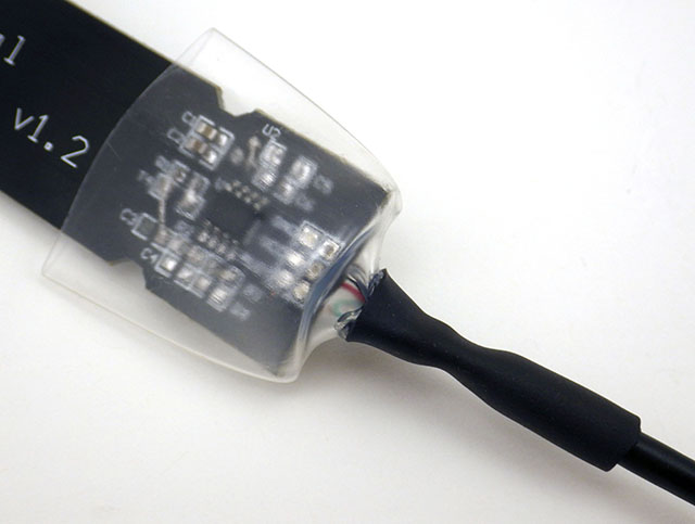 3/4″(18mm) to 1″(24mm), 2:1 heat-shrink forms a container around the circuits, with smaller adhesive lined 3:1 at the cable to provide a seal to hold the liquid epoxy. |
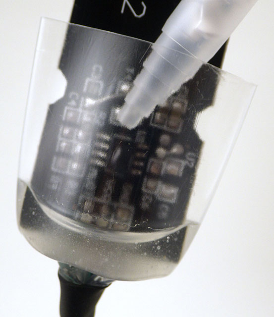 Only fill to about 15% of the volume with epoxy. Here I’m using Loctite E30-CL. This epoxy takes 24 hours to fully cure. |
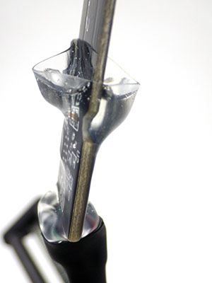 GENTLE heating compresses the tubing from the bottom up. This forces the epoxy over the components |
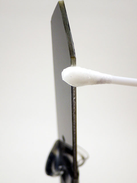 Before finishing, use a cotton swab to seal the edges of the probe with the epoxy. Cut PCBs can absorb several % water if edges are left exposed. |
 Complete the heating over a rubbish bin to catch the overflow & wipe the front surface of the probe so that you don’t have any epoxy on the sensing surfaces. |
Soil moisture sensors measure the volumetric water content of a soil indirectly by using some other property such as electrical resistance or dielectric permittivity. The relation between the measurement and soil moisture varies depending on environmental factors such as soil type, temperature, or the amount of salt dissolved in the pore water. This is kind of obvious if you think about how differently sand behaves with respect to water infiltration & retention compared to a soil high in clay content – but the low level details get quite complex.
I generally use our Classroom logger for backyard experiments. You want at least 2-3 monitoring locations due to the spatial variability of infiltration pathways, and then 2-3 sampling depths at each spot for a complete profile. Agricultural applications usually install two sensors, with one shallow sensor at 25-30% of the root zone depth and one deep at 65-80% of the root zone depth. But research projects install up to one sensor every 10cm through the soil profile. If you are doing that then you might want to install the sensor boards parallel to the ground surface and only power them one at a time so they don’t interfere with each other.
Vernier outlines a basic volumetric calibration procedure for soil sensors which starts by measuring soil from your target area that’s been dried in an oven for 24 hours. To get another calibration point you add an amount of water equivalent to some percentage (say 5%) of that soils dry volume and take another sensor reading after that’s had a chance to equilibrate. To get a complete response curve you would use 5-10 jars of dry soil, adding different relative %-volumes of water to each pot from 5 to 50%. (Even in clay the %volume of water at field capacity is usually less than 50%.) Then you can interpolate any intermediate sensor readings with something like Multimap.
If the distance between interdigital coplanar electrodes is comparable to the smallest dimension of each electrode, then ‘fringe fields’ are significant. As a rule of thumb, the field usually has a penetration distance of between 0.5-1x the distance between the centers of the electrodes. I found several papers modeling that as one third of the width of the electrode plus the gap between electrodes: EPD ≈ (W + G)/3. In this case I estimate the useful sensing distance is less, say 3-6 millimeters from the probes surface, so you have to take care there are no air gaps near the sensor surface during the calibration, and when you deploy. Agricultural sensors are often placed in an augured hole filled with a screen filtered soil slurry to avoid air bubbles. One of the biggest challenges is that even after a good deployment, the soil dries out and ‘break away’ from contact with the surface on your sensor. This will give you grief with almost all of the soil measuring sensors on the market. (with the possible exception of neutron probes) Another issue with this method is drilling the hole necessarily cuts any moisture pulling roots away from the probe, creating offsets relative to the root-permeated soil nearby.
The story gets more complicated with respect to growing things because the pores of a sandy soil might provide more plant available water than absorbent clay soils (see: matric potential) So it’s worth taking the time to determine the texture of your soil, and you have consider the root depth of your crop. (typically 6-24 inches) With all the confounding factors, soil sensors are often used in the context of ‘relative’ boundaries by setting an arbitrary upper threshold for the instrument’s raw output at field capacity (~ two days after a rain event) and the lower threshold when plant wilting is observed. Soil moisture sensors also need to be placed in a location that receives a similar amount of sunlight to account for evapotranspiration. Then there’s all the factors related to your sampling technique.
Using ‘field capacity’ as our upper limit might make it possible to do a basic three -point calibration of your sensors: Dig your trench and take ‘in situ’ measurements with your probe before you disturb the rest of the soil. Extract two samples with a tubular ‘cutter’ who’s volume is large enough to cover your sensor and weigh them (you can back-calculate the gravimetric % moisture for those in-situ readings later from the sample you dry out ). Dry one completely in an oven and the raise the other one to field capacity by adding water and then letting it drain & stabilize for a day or so in a 100% humidity chamber. (a big zip-lock bag?) The wet sample must be allowed to drain under gravity until water is no longer actively dripping from it. Then weigh both samples again & take readings with your sensor embedded in the wet & dry soil samples packed back into their original sampling volume. The tricky part is that you probably need to use a metal tube for cutting your sample (and for the oven drying) but you don’t want metal near a capacitance probe later on – so you would want to transfer your soil plugs into a PVC pipe with the same internal volume using some kind of plunger before the final measurements. The idea is you want to keep the relative ‘density’ of the sample similar to the original soil insitu.
The Hack: (click images to enlarge)
After testing some ‘naked’ boards ( where I had removed all the components) I realized that the bare traces fell within a workable capacitance range for the same astable configuration the timer was already configured for:
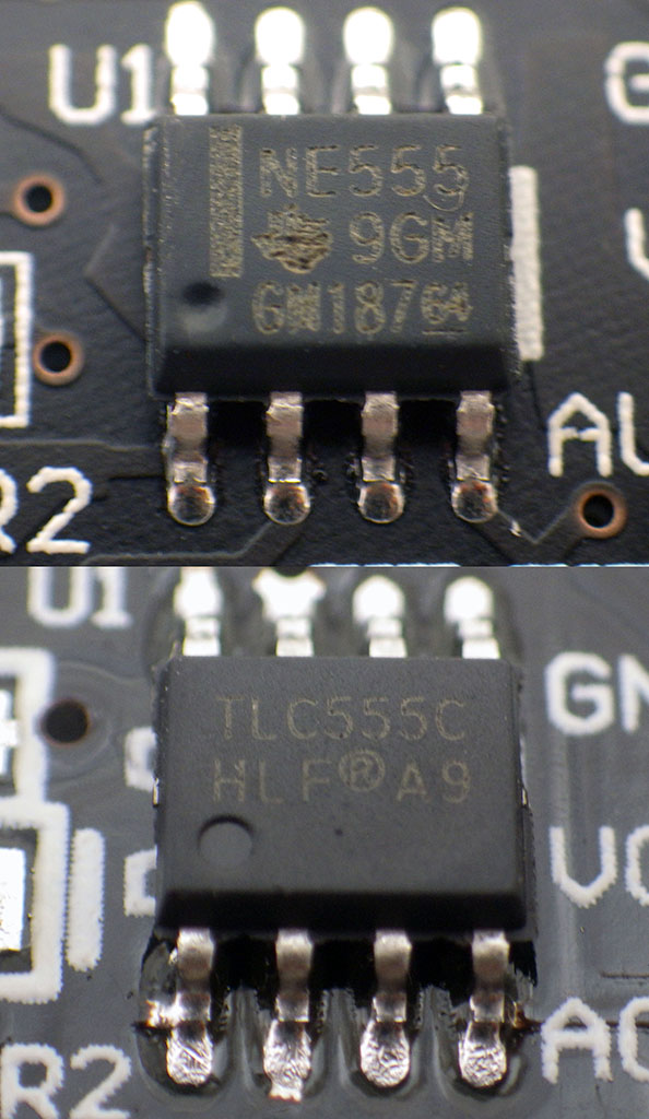
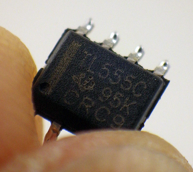
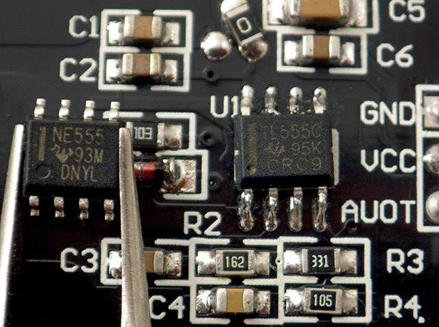
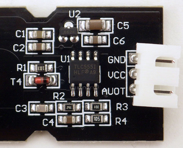 Get the regulated boards with the CMOS TLC555 chip rather than the NE555. 3.3v operation is out-of-spec for the NE and 1/2 the NE’s I’ve tried didn’t even work in their default analog config at 5v. (& the 3.3v 662k reg is below spec if your supply falls below ~3.4v) |
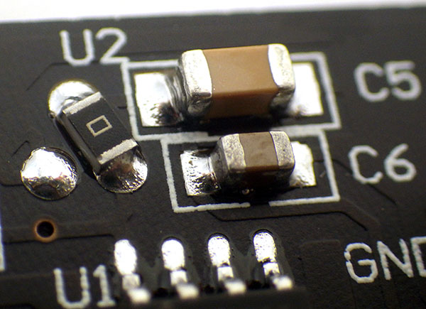
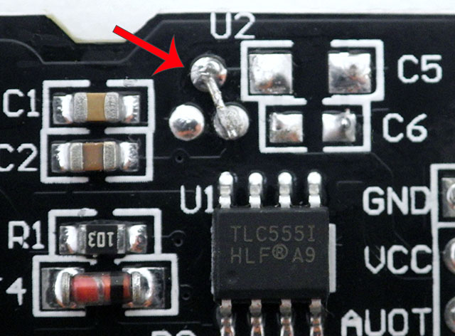 I remove the regulator & bridge the Vin to Vout pads. If you are going to pin-power the sensor you also need to remove the reg caps C5 (10µF) & C6 (160nF) as their inrush current could damage your MCU. Or add ~150 limit resistor in series, but that will drop output voltage. |
 Note that some variants of these sensors come with the regulator already removed DO NOT BUY THESE BOARDS – they use older NE555 chips which won’t operate at 3.3v. |
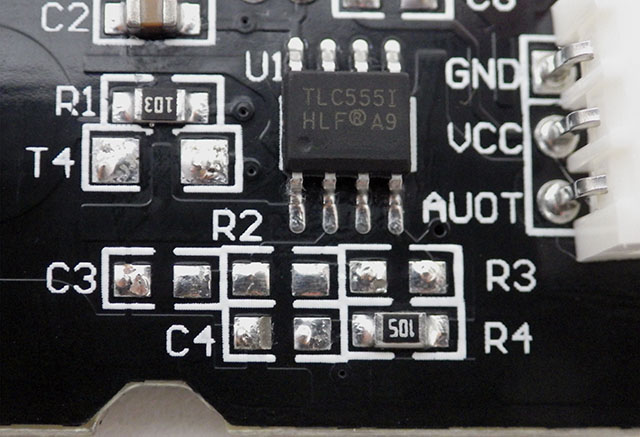 Remove the T4 diode, C3 & C4 caps and R2& R3 resistors as shown. |
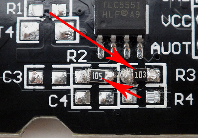 Move the10k R1 to the R3 pads, and the 1Meg ohm R4 to the R2 pads. When the new R2 exceeds is more than 10x the new R3 resistor you approach a 50% duty cycle on the FM output. |
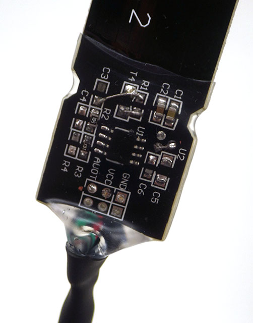
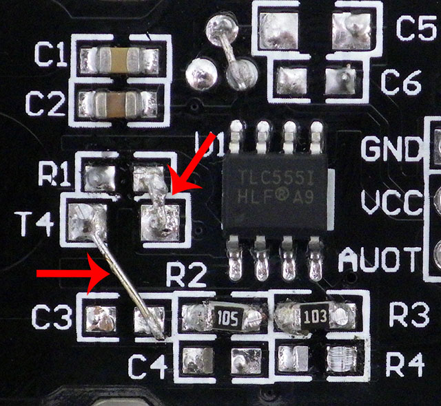 Bridge the R1/T4 pads closest to the 555. This patches the frequency output to AOUT. Linking the other T4 pad to C3 replaces put’s the probes capacitance in its place. |

There isn’t much left after the mod. It’s important to leave the C1 bypass in place but I haven’t had problems pin-powering other sensor boards with similar caps. It’s the bare minimum you can get away with. (& add a series limiter if pin powering)
It’s worth mentioning that the 555’s notorious supply-current spikes during output transitions might give you bad reads or weird voltage spikes. I tried pin powering anyway because the TLC555 is so much better than the the old NE555s which would surely destroy any IO pin used to supply it. So I’m sailing pretty close to the wind here: it would be much wiser to just leave the original C5/6 caps in place and skip pin powering all together. Using a mosfet is the safer choice, but hey – this is a hack…right? Officially, as little as 0.1uF needs a limit resistor to protect I/O pins, but ‘unofficially’ pin-powering dodgey circuits with AVR pins is surprisingly robust.
With the probe capacitance varying from <30 pF to ~400 pF (air/water), using 1M/10K resistors on the R2&R3 pads will give you about 50 kHz output in air, and ~1.5 kHz in water. Or you could drop in your own resistor combination to tune the output. Our ProMini based loggers have a relatively slow 8MHz clock so the upper limit for measuring period intervals is about 120kHz before things get flakey. On a 16MHz board you can reach 200 kHz easily and with a faster MCU you could tweak that to even higher speeds. But at first bounce, with parts I already had, the 1M&10K combination seemed workable.
the TLC555 draws far less current and works at 3.3v. It can also be pushed to 2 MHz in astable mode, though you’d need a more advanced counter to keep up. LMC555 & TLC551 work at even lower voltages than TLC555
You have variety of options to read pulsed signals with an Arduino. We reviewed those in the ‘Adding Sensors to an Arduino Datalogger‘ but the short version of that is: Tillart’s TSL235R example works, or you could try PJRC’s FreqCount Library. Gate interval methods count many output cycles. This reduces error and lets you approach frequencies to about 1/2 your uC clock speed (depending on the interrupt handling). However at lower frequencies the precision suffers, so measuring the elapsed time during a single cycle is better. Since I’ve already switched over to using the Input Capture Unit to read thermistors, I started with Reply #12, on Nick’s Timers & Counters page. This works with these hacked soil sensors, though it will occasionally throw a spurious High/Low outlier with those rounded trapezoidal pulses. Putting a few repeats through Paul Badgers digital smooth filter crops away those glitch reads and median filters are also good for single spike suppression. Denes Sene’s Simple Kalman filter is also fun to play with, though in this case that’s killing flies with a sledge hammer.
As usual, I pretty much ignored all the calibration homework and simply stuck the thing in the ground for a couple of weeks to see what I’d get. Which was fortunate in a way, because the sensor developed a problem which I probably would have missed during short calibration runs:
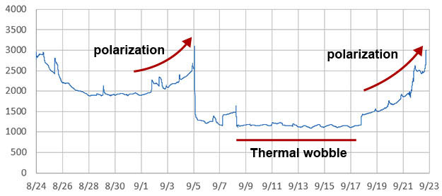
Probe Frequency [Hz] (left axis) at 5cm soil depth. Rain event on 9/5 reset the probe to normal for a few days.
The daily thermal wobble was expected, but the probe repeatedly displayed an upward bend which did not match the daily ‘stair-step’ drying cycles seen with other nearby soil sensors. Were we slowly pulling the ions out of the soil matrix? Rain events would reset back to normal behavior, but eventually the rising curve would happen again. Perhaps that was because the water was leaving, but the ions were being held on the probe surface? When I looked into the frequency of commercial sensors, they were running at least 100 kHz, and most were in the 10’s of MHz range. Some of them automatically increased frequency with increasing conductance specifically to avoid this type of problem.

While the heat shrink/epoxy method is our gold standard for sensor encapsulation, adhesive lined 3:1 heat-shrink can do a reasonable job on these sensors if you make sure the surfaces are super-clean with isopropyl alcohol & take time to carefully push out any air bubbles. (use gloves so you don’t burn your fingers!) A third alternative is to use hot glue inside regular heat shrink tubing – squashing it into full contact with the circuits while the glue is still warm & pliable. You still have to treat the edges of the PCB, but that can also be done with nail polish. While much faster to prepare: the heat-shrink (shown in the photo above) & hot glue methods will‘pull away’ from the smooth sensor surface after about 1 year in service – epoxy encapsulation lasts for the lifetime of the probe.
I also tried to measure the electrical conductivity of solutions with this hacked probe. But without polarity reversals, polarization again became a limiting problem – and this only gets worse if you increase resistor values to resolve more detail with slower 555 pulses. So at low freshwater conductivities, where polarization is negligible, the probe works ‘ok’ as a low-resolution EC sensor if you take your readings quickly & then de-power the probe for a long rest period. (while stirring the heck out of it..? ) However the readings ‘plateau’ as you approach 10 mS/cm – so it’s not much use in the kind of brackish coastal environments we play in.
At it’s heart, this is just a variation of standard RC rise-time methods with the 555 converting that into pulsed output. While my attempts with the 1M&10K pair didn’t deliver much, the parrot ain’t dead yet. Changing that R2/R3 resistor combination to boost frequencies to much higher frequencies when the probe is in dry soil might reduce that polarization problem. Or, with a fixed capacitor instead of the probe I could try replacing a resistor with some plaster of Paris & carbon rods for a matric potential sensor with pulsed output. Essentially using the circuit as a cheap resistance to frequency converter.
And then there’s all the other capacitive sensors that I could jumper onto the C3 pads. At that point I might as well get out the hack-saw, because I’m really just using the top section of the board as a TLC555 breakout that I can mount under epoxy. When you consider how many of us are working with 3.3v MCUs, a low voltage 555 module should have been on the market already. And while I’m thinking about that – where are all the 3v op-amp boards, with each stage jumper-able into several ‘standard recipes’, and linkable to the next by solder pads or holes along the outer edge? I’m envisioning an SMD quad in the middle, and a few layers of elegantly designed traces & well labeled through-holes for population with resistors & caps. Even at eBay prices, you’d think the mark-up would have made those common as dirt a long time ago . . .
Addendum 2023-12-11
Daniel Robertson posted some pictures of the electrode problems with these cheap soil sensors and his attempts to fix them.
Selected References:
- Soil Sensor
- Gadget Reboot: Capacitive Soil Moisture Sensor Test
- Characterization of Low-Cost Capacitive Soil Moisture Sensors for IoT Networks
- Effective Calibration of Low-Cost Soil Water Content Sensors
- Calibration and Validation of a Low-Cost Capacitive Moisture Sensor…
- Soil Water Dynamics [nature]
- Methods & techniques for soil moisture monitoring [University of Wyoming]
- The soil water compendium [Edaphic Scientific]
- Methods to Monitor Soil Moisture
- Field Devices For Monitoring Soil Water Content
- Soil moisture and matric potential – an open field comparison of sensor systems
- Understanding Soil Water Content and Thresholds for Irrigation Management
- Selker and Or: Soil Hydrology and Biophysics
- Soil Moisture Sensor Installation [Decagon Devices]
- Soil Moisture Profile Probe Using a Capacitive Touch Sensor
- How to convert gravimetric soil water content to volumetric soil water [Edaphic]
- Installation of Soil Sensors for Irrigation Scheduling [& identifying bad data]
- Understanding Soil Water Content & Thresholds for Irrigation
- Calibrating Soil Sensors with a 1 month dry-down & weight measurements
Addendum: 2020-12-18
- The Food and Agriculture Organization of the United Nations has released its first ever global assessment of biodiversity in the underground world.
- A video about plant roots competing with each other under ground.
- And finally a cool looking antique gauge hack . It’s too bad they didn’t use a capacitance sensor with it – those two prong resistive soil sensors usually corrode within a few weeks.
The analog soil sensor from the start of the post is still chugging away, but (with the exception of a few rainy days) after leaf-fall the soil sensor has basically leveled out at ‘field capacity’
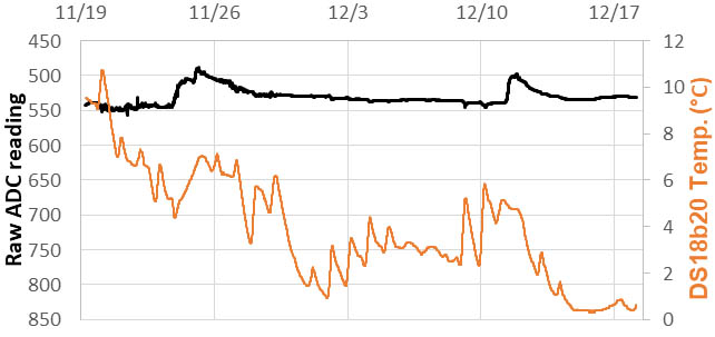
Two heavy rain events in this record. With no more evapotranspiration, the soil stays saturated between them.
So there won’t be much going on over winter but, I will be leaving most of the loggers outside anyway. We have some northern projects waiting in the wings and I want to see how well the unregulated student builds stand up to the cold. Be interesting to see if the soil sensor can withstand being frozen right into the soil. I expect those events will register as ‘extremely dry’ due to the reduced dielectric of ice.
Addendum 2021-05-02
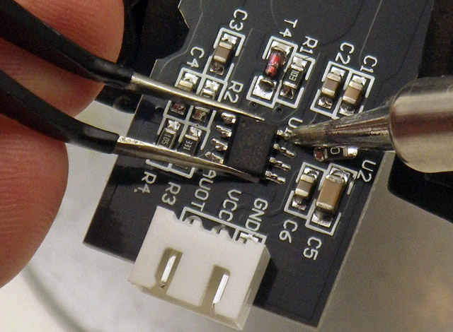
Lately it’s been challenging to get the 3.3v regulated versions of theses soil sensors. Vendors on eBay have started listing 3.3-5v compatibility, and even posting the schematic showing the regulated TLC555 circuit, and then shipping the ‘5v only’ NE555 sensors. This kind of bait & switch is common with low end stuff from China and the problem is your shipping charge from the US back to Shenzhen usually costs more than the items. So I just started replacing the NE555 chips myself, since TLC555’s are only about 50¢ each:

The Touchstone TS3002 timer IC could be another interesting 555 replacement option as it’s spec’d to draw only 1μA from a 1.8-V supply. A drain that low brings these soil sensors within the power budget of our 2-Part falcon tube loggers that run for a year on a coin cell.
Addendum 2023-03-18
From an electronics point of view, putting stuff in the ground isn’t really much different than putting it underwater. So people reading this post will probably some more useful information in our post about Waterproofing Electronics Projects.

Hey Edward, I’m looking into using machine learning to detect anomalies or patterns in soil moisture data, which may only be detectable in post processing. For example, in your addendum, detecting some sort of a pattern after the two heavy rain events compared to the expected daily ‘stair-step’ drying cycles you mentioned earlier.
Would it be possible for you to share your raw (soil moisture and temperature) sensor data? I’m like to have a look at the historic patterns to see if it’s actually possible to create a machine learning model. The model itself would not be relevant to me since my soil is different, but having actual, historic raw data, as opposed to creating a set of random data points, would give me a better idea if it’s possible or not.
Thank you,
I’m afraid I have to decline. I still consider the soil sensor work as ‘mid-experiment’, which means that what I have are a bunch of different runs with various hardware and software hacks applied, that dramatically change the sensor response (in some cases negatively). I will be installing a number of these next spring in a more organized way as part of a new tree monitoring experiment, but won’t really have data consistent enough for a decent training set till next winter.
Pingback: Sensor de tierra con capacidad de pirateo para suministros de tensor inferior - la-tecnologia.com
Can we use that like grain moisture meter? ranges between 8% to 35% in beans, 5% to 25% in corn
The penetration depth of the field is very low on these sensors and dielectric delta for air is almost two orders of magnitude different than water. So it would be tricky to get good readings because of irregular packing of the grain/corn against the sensing surface -and this would also be shifting over time. But it might be possible with readings from multiple sensors and some kind of a heavily averaged approach to deal with the inconsistencies from all the air gaps.
Pingback: El amperímetro vintage se convierte en varios medidores de humedad - la-tecnologia.com
Pingback: Bodenfeuchtesensor mit ESP8266 | theloxleyfiles