

In this shot you can really see how the addition of the drag flag amplifies the tilt signal.
Then next day saw some routine logger replacements at our favorite coastal cave. It’s relatively shallow, making it a good place for a shakedown dive, and we have plenty of air time to develop funky new underwater deployment procedures for our little bots. The fact that it’s also an un-decorated mud pit is just gravy, as it means that no one bothers our instruments like they would in the prettier high-traffic caves. Strong tidal influence also provides a good range in the data and this cave has been continuously instrumented since our alpha trials back in 2013.
Of course that also means this location has seen more instrument failures than anywhere else, and again it delivered some bad news with the good: showing that even a great sensor can eventually crack under pressure:
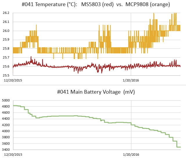
This logger had been performing well since mid 2015, and initial consumption curves indicated it should go a year or more on 3AA’s. But we had some hints in the last dataset that the temp sensor was struggling, and this time it burned through a set of batteries in less than six weeks, with the 9808 reporting imaginary temperature excursions very similar to those we saw from the TMP102 failures last year. Each was accompanied by a significant hit to the power supply, which would imply that we probably had some kind of pressure induced self heating going on inside the IC. (perhaps because of a short?)
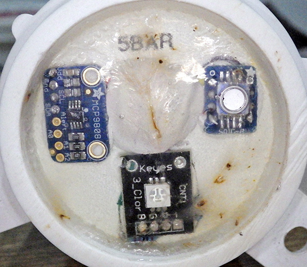
The wonky MCP9808 after 9 months. On newer builds I have moved away from high surface area sensor wells as I think they might subject the sensors to larger bowing forces at depth. The LED also became flaky, with only the blue channel still operating.
That’s a bit of a bummer, because the MCP’s offer better off the shelf accuracy than most of the other temperature sensors in that price range. So unless I want to put the breakout inside the housing, I’m forced back to the humble DS18B20’s that I used at the beginning of the project. I had a feeling this might happen, so on this trip we deployed a special 3-sensor cap on one of the loggers, with sensors inside the body, embedded in epoxy, and one projecting directly into the water. Hopefully that will let me determine how much lag we get from moving the temp sensors inside the pvc shell. Since we typically don’t take readings more than once every 15 minutes, I’m hoping we don’t see much effect from the different arrangements. During basement testing, thermal inertia rounded off short temperature peaks significantly, but that was at a five minute sampling interval, in air rather than water.
Even with calibration, you still need some way to determine the mounting offsets.
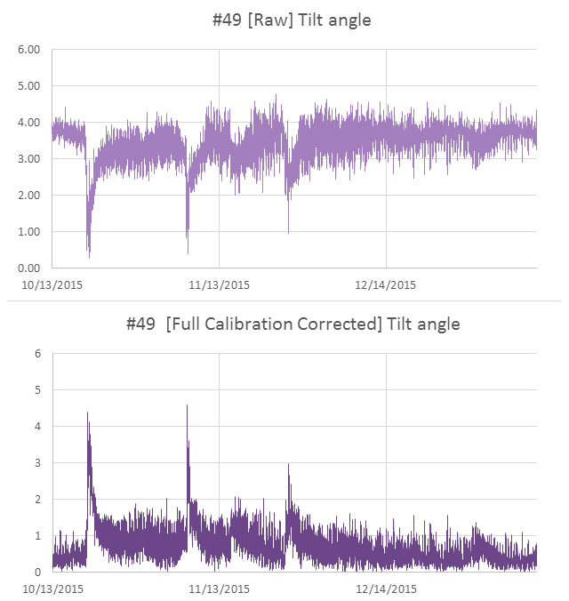
All three flow sensors delivered beautiful records, and the worst build actually provided the best insight into the need for sensor calibration. Logger #69 had a 5° tilt error due to an adhesive failure during the build. At that time I was still learning how to calibrate the sensors, so I was doing estimates of sensor mounting offsets by simply averaging the readings from an overnight test where I hung the logger on a pivot joint. The relatively large error on #69 meant that I almost rejected that sensor cap outright, but I figured we should put the unit in a high velocity site to test if it was still usable. I later did a full calibration on that unit (with Magneto 1.2 software) to generate a more complete set of axes bias & scaling factors.
With the latest flow data in hand, I could now see how much difference the extra effort of full calibration makes:
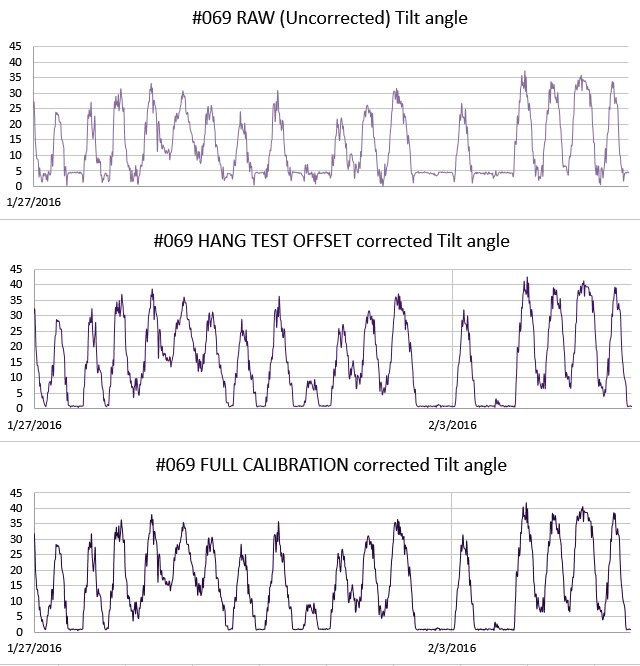
Those two corrected sets differ by a maximum of 0.5 degrees, implying that I can generate pretty good correction factors for older gen units in the field by simply hanging them in a closet over night. This also gives me a way to keep tabs on sensor drift without completely reprogramming the loggers, which I usually don’t have time for during fieldwork.
This is probably ‘good enough’ for our high flow sites, but for the deeper saline deployments (where the flows creep along in the sub-cm/second range) I’ll probably have to go full Monty since half a degree might be a significant portion of the total signal. And I have accumulated enough compass calibrations by now to show that in comparison to the well behaved acclerometers, magnetometer correction factors are all over the map with bias & offsets sometimes approaching 20%.
Spotted in Tulum:

Working with a five degree mounting offset…
Addendum 2016-04-10:
Still processing the data from this last trip, and I found a good example from of one of those low flow systems, where the full calibration was needed to correct the axes bias errors:
Once you get down into the weeds, the factory offsets are larger than your signal, potentially hiding the phenomenon you are looking for. And you still have the challenge of filtering out the relatively high acclerometer noise, without destroying the more subtle tidal signals…
Addendum 2016-04-30:
I can only imagine what kind of incredible calibration challenges faced the people who made first direct observations of a gravitational wave, but I think I’m beginning to understand the sentiment behind this awesome tattoo…
Addendum 2016-05-06:
Hackaday just posted about an elegant new tilt sensor idea, using a variable differential transformer filled with ferrofluid. This principle of variable inductive cores has been used for years by YSI to detect salinity, but seeing this fellows approach makes me want the look at the technique again, if I can figure out a way to reduce the power consumption…
Addendum 2016-07-30:
We had another MCP9808 from that gen. go down, but this time the power curve was the exact opposite of what I am used to seeing for IC sensor failures:
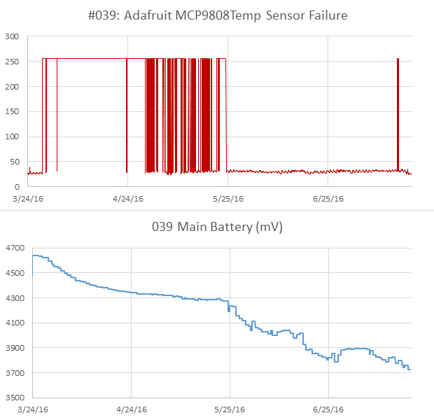 While the sensor was throwing out a string of ‘Maximum Reading’ errors, the power consumption for the logger was normal. Then the sensor started delivering normal data again, but was obviously drawing enough juice to take the rest of the logger down quickly. Weird…

Can you confirm that the sensor problems are actually caused by pressure? Typically applying a uniform external pressure is not very problematic for most SMD components. For ROV applications some electronics boards are operated in a depth of several thousand meters without a pressure chamber (either with potting or in a simple oil-filled case to compensate the external pressure). I also don’t see any physical reason why a temperature sensor should be particularly sensitive to external pressure.
Maybe it is possible to debug this issue in a lab environment with an improvised pressure chamber. A depth of 50-60m is about equivalent to the maximum pressure of a standard bicycle tire and so simulating this pressure just requires a cheap bicycle pump (preferably with a manometer) and a matching valve (which can be glued in to an appropriate chamber). For safety reasons the pressure chamber should be filled with water instead of air (to minimize the stored energy which could be released in case the chamber fails).
I also have one idea to limit the impact of one failing sensor (especially with a long chain of sensors): Powering off the sensor/sensor chain between the measurements. For an I2C sensor it should be safe to switch off the ground connection with a (logic-level) N-channel mosfet while VCC, SDA and SCL can stay connected (due to the pull-up resistors, everything is then tied to VCC and it can’t pull any more current). So any leakage current (e.g. damaged wire) or increased sensor consumption (e.g. defective sensor failing to enter shutdown mode) only has a chance to empty the battery for a small percentage of the overall runtime of the data logger. Given the low (200µA) supply current of the MCP9808 it should also be possible to use a standard GPIO pin directly (with switching between GND and High-Z) to power a certain number of sensors.
Alas, like so many of the things in this project, I haven’t the time left to setup a proper experiment on those sensor failures. Moisture creep is another probable cause, but since all the solder surfaces were still polished and shiny under the clear Loctite e30CL epoxy I used to pot them, I assumed that was not the primary issue. My deduction that pressure was the primary cause was the result of several hull-mounted temp sensors (Tmp102’s & MCP9808’s) working fine at ~5m, but failing shortly after those same loggers were deployed at 30m. Heck, a couple of them barely made it through the deployment dive before they went squirrely. When I looked at the data overall, the temp sensors did not fail if they were deployed around 5m, even on deployments longer than two years, but they all eventually failed when placed deeper. This might not be a weakness of the chip, but the flexing of the housings & epoxy exerting some kind of twisting force. There is also the question of how the pressure might have affected the other SMD passives on the breakout modules..? At the moment I’m just putting them all on the inside of the housings, but that introduces a significant amount of lag.
I use pin powering for the DS3231 RTC’s and I’ve been very happy with the results so far, but that’s a device with a fail-over mode built into the chip. My guess is that typical datasheets won’t give you the ‘maximum safe number of power cycles’ for I2C chips that are already designed provide low current sleep modes. Another thing about pin powering is that I’ve found the main battery discharge curve is one the best overall diagnostics of problems with a logger, since the alkaline AA batteries we use have smooth mostly linear behavior. Even when the data is Ok, I can still tell something is wrong if the battery curve gets too bumpy. It would be easy for a progressing component failure to hide if I was only powering it at read time.