
A ±2ppm DS3231N for less than $1? The industrial SN variant is rated for a wider -40°C to +85°C temp range than the N. The ±5ppm -M variant has dramatically different noise/drift characteristics..
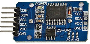
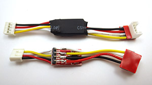
Since the Cave Pearl is a data logger, it spends most of the time sleeping to conserve power. So you could say that the most important sensor on the unit is the real-time clock (RTC), who’s alarm signal wakes the sleeping processor and begins the cascade of sensor readings. I built the first few beta units with the DS3231 Chronodot from Macetech (about $18 each), but I kept on stumbling across cheap RTC modules on eBay, Amazon, etc. and I eventually bought a couple to try them out. While I waited for them to ship on the proverbial slow boat, I did some digging, because these modules were (almost) selling for less than the chip itself if I bought them directly from trusted sources like Digikey, Mouser, etc.
So perhaps they are counterfeit chips, which are simply pin & code compatible? I also found rumors about “ghost” shifts, where legitimate manufacturer plants/equipment are used off the clock to produce extra parts. Or legitimate production runs which test out defective (if 10% of a run’s chips are bad, they often scrap the entire run) but someone intercepts the chips before they can be destroyed, and they resurface on the grey market. But even with all these possibilities in mind, I still have to make the Pearls as inexpensive as possible if they are going to be deployed in large numbers, and having an I2C eeprom on the board for the same money, made the temptation too great to resist.
When the RTC’s arrived they had an LIR2032 rechargeable battery underneath the board, and a LED power indicator above. I had a feeling that neither of these were going to be friendly to my power budget so I went hunting for the schematics to see what I could do to improve the situation. I quickly found an Instructables post which described how to remove the battery charging circuit from a very similar DS1307 module, and then I found the datasheets and schematic for this DS3231 module over at at a site in Europe. Most of the parts were pretty straight forward:

But thanks to the tutorial by msuzuki777, I immediately zeroed in on a few parts on that circuit diagram that could be removed:

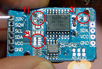
The power indicator (1) was pretty pointless, so that was the first thing to go. I already had pullups on the I2C lines, so they were not needed here, but they were in a combined 4 resistor block, which meant that to get rid of the pullups on SCL and SDA, I also had to remove the pullup on the alarm line. This had me a little concerned, as that alarm line is vital to the whole design. Without that resistor on SQW, I am relying on the weak internal processor pullups keep the alarm line high with:
digitalWrite(INTERRUPT_PIN, HIGH); //pull up the interrupt pin
Fortunately the pin stays high in all sleep modes and so far everything has been working with this setup (so fingers are crossed….again… 😉 )
Then I looked at the 200Ω resistor & 1N4148 diode (3) that are supposed to provide a trickle charge to the rechargeable battery, though the folks at BU suggest this is a bad idea. The LiR2032 that these modules ship with is 3.6v, and while capacity varies depending on where you buy them, most provide 35mah to 45mah capacity. Looking at the power draw from the DS3231, a fully charged battery would keep the unit backed up for at least 200 days (in a perfect world, with no self discharge, etc) But, it requires a 4.2v charging voltage for maximum charge, so vcc would have to be above 4.3-ish volts. I don’t anticipate my 3x AA power supply staying in that territory for the duration of a long deployment (especially if I end up powering the units from cheap AA’s) so there really was no compelling reason to keep the charging system in place. Once I de-soldered the resistor, I popped in a CR2032 (3v 240mAh) as a replacement which should backup the clock for several years of operation.
Libraries for that RTC?
I am using the Date, Time and Alarm functions in the library from Mr Alvin’s github,
which is based largely on Jean-Claude Wippler’s (aka JeeLab) excellent RTC library.
And it’s worth noting the clear alarm interrupt issue over in the Arduino playground.
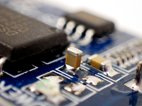
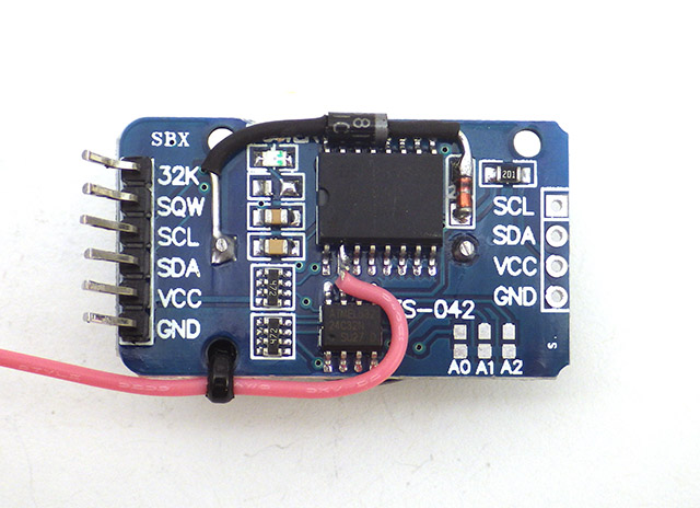
Then we come to the AT24C32N (2.7 to 5.5v) memory chip that is also on this breakout board. Another of those 4 resistor bricks is lifting pins 1,2 and 3 to Vcc, so according to the eeprom datasheet this unit is being set to 0×57 on the I2C bus. There are pads there to ground out these lines if you need to reassign the address to something else. Although I have already determined that eeprom is not the power savior I hoped it might be (all that eeprom reading & writing uses about 1/3 the power of simply writing the data to the SD card in the first place) it’s presence lets me be really lazy on the coding and just pop any numbers or characters that I want into a PSTRING’d buffer which then gets sent to a standard eeprom page writing routine. This flexibility allows me to swap sensors with dramatically different output, while retaining essentially the same code to handle the eeprom loading and the transfer of data back out to the SD card. If you want more information about that you can head over my earlier post on buffering sensor data to an I2C eeprom for the gory details.
The May 2014 build of the data logging platform, which used a hacked Tinyduino light sensor board to regulate & pull up the I2C bus. SQW is soldered to interrupt pin 2. Later in 2014 I switched to Pro Mini style boards with 3.3 v regulators, so I left that four resistor block in place ( 2 in the schematic above) to provide I2C and SQW pullup.
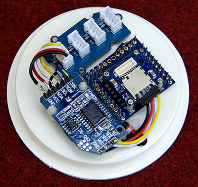
To top it all off, the cascade ports on the far side of the module let me “just barely” fit the rtc, the I2C hub (with corners sanded off), and main TinyDuino stack onto the platform in the middle of my housing. I am lifting the voltage regulated I2C bus traces from the TinyDuino light sensor board, so I am also hunting around for an off the shelf vreg & level shifter combination to replace that hack (because that bit of soldering is a pita). But overall, I am very happy with this build, as all the central data logging functions have come together into a nice securely mounted package, that should withstand significant knocking about during the deployment dives. Of course there is plenty of field work testing still to be done, so time will tell (sorry, couldn’t resist…) if these cheap RTC’s will cause more trouble than they are worth.
Addendum: 2014-05-21
It just occurred to me that sooner or later Tinycircuits will be releasing an RTC board, and that will give me a chance to directly compare these cheap boards to a “trusted” clock signal provided that their chip does not want the same bus address. Or if their clock wants the same I2C bus address as this eBay RTC, I could use a DS3234 on the SPI bus. I will post an update when I can run that test to spot clock drift, alarm errors, etc. Several sites have mentioned that real DS3231’s drift about 2 seconds per month, while the cheaper ds1307’s drift 7-10 seconds per day. If you have the right equipment, you can make the chip even more accurate by adjusting the aging offset register.
Addendum: 2014-05-21
I just realized something else odd about my setup here. The I2c bus is held at 3.3 volts by the regulator on the tiny light sensor shield, but I am pulling up the SQW via the tinyduino cpu, which is following the voltage on the battery pack because the tiny CPU is unregulated. So the pull-up voltage on the alarm line is out of sync with the voltage seen by the rest of the DS3231 chip….hmmmm.
(2014-10-28 : data sheet says its Ok to pull the line all the way up to 5v, even on Vbatt)
Addendum: 2014-07-01
I created a very inexpensive 3-component data logger with this RTC, a Pro Mini mcu board, and a cheap sd card adapter. And you can see a post about the latest version of that logger concept here which has added a power shutdown feature. In those Pro Mini based loggers I do not remove the I2C pullup resistor bank as shown earlier in this post (2 in the photo above), as the removal is only needed if you already have pullups in place, as I did when using the hacked Tinyduino light sensor board to drive the RTC. I have built many loggers now, and some of them have come close to 400,000 alarms & eeprom write cycles, so these cheap RTCs are proving to be pretty durable.
Addendum: 2014-10-28 Pin Powering the RTC
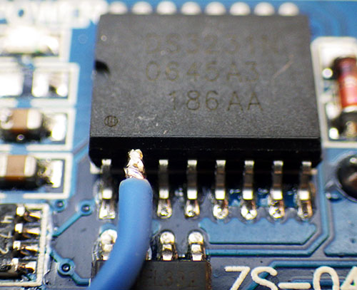
Wedge a tweezer tip behind the pin and “gently” lever it away from the board as you apply an iron to the pad. Then solder your pin-power jumper directly onto that raised leg. At this point the chip’s Vcc pin is no longer connected to the Vcc line on the breakout board, so you can leave power on the board’s Vcc line to pullup SDA,SCL,SQW and supply power to any I2C devices / sensors you have connected to the cascade port.
I have noticed that when I power this module from Vcc at 3.3v, it draws around 89 µA. But according to the datasheet,the RTC should only draw ~2 µA on average when powered from Vbat. (1µA baseline plus about 500µA for 100ms every 64 seconds when the crystal is doing temperature compensation) Nick Gammon found an elegant way to power a DS1307 by connecting Vcc to one of the Arduino pins , driven high in output mode when the system is active. (look about half way down the page) When the Arduino pin is low, the clock reverts to battery power, and goes into the low current timekeeping mode. But according to the datasheet, Bit 6 (Battery-Backed Square-Wave Enable) of control register 0Eh, can be set to 1 to force the wake-up alarms to occur when running the RTC from the back up battery alone. [note: This bit is disabled (logic 0) when power is first applied] So you can still use the RTC to wake the Arduino, even if you have de-powered it by bringing the pin low. I have tested this and it seems to work fine on my RTC modules, reducing the sleep current by about 70 µA. (or ~ 600 mAh per year = almost 1/4 of a AA) Tests are underway now to see if this is stable as a direct jumper to the pin without using a current limiter, which might give me a problem with inrush current unless I also add a resistor as N.G. did. Also keep in mind that this only works because the RTC was designed with backup power circuitry. In general, de-powering I2C Slaves is not a good idea because the pullup resistors keep the SDA and SCL lines high. When a regular I2C sensor has no power, you could leak current via SDA and SCL through the I2C device to GND.
And since my loggers are going in caves where the temperature does not change very quickly, I am bumping the temp conversion time from 64 to 512 seconds as per Application note 3644, in theory reducing the battery drain to < 1 µA. It’s a little unclear from that datasheet if this only really works on the DS3234 (?) but if it does this puts the battery discharge on par with electrolyte evaporation if Maxim’s coin cell lifespan estimates are to be believed.
And finally, doing this means that you are relying on the Cr2032 to power the clock for a substantial amount of time, so you need to make sure you are not using fake coin cell batteries. Name brand packaging is no guarantee of good batteries either! In learning this little lesson I discovered that you can not simply read a CR2032 coin cell with your volt meter to determine if it is healthy, as the no-load voltage stays above 3v even when the cells are nearly dead. As per the Energiser datasheet, I read the cell with a 400 Ω resistor pulse load (for 2 seconds). If that gives me >3v I call the cell good. If you are stuck out in the field without a meter, check if the battery bounces well.
I do wonder if its worth putting a 100uF multilayer ceramic capacitor on the coin cell to buffer the impact of the alarm events. But I don’t know how much I would then loose to capacitor leakage. Abracon seems to think its a good idea in their application note, claiming 11 µA leakage for a 100µF MLCC. But that is more than 3x the current draw of the DS3231 in timekeeping mode.
NOTE: If you try powering the entire breakout board from a digital pin, you are essentially turning the onboard SDA & SCL resistors into pulldown resistors and these fight against the Atmels internal pullup resistors on the 328 that get enabled by default in the two wire library. For details on how to fix that problem, check out this post on the Arduino playground: DS3231 drawing 200+µA through SDA/SCL Also note that I had to go all the way to (x86)\Arduino\hardware\arduino\avr\libraries\wire\utility to find the twi library on my machine, but if you power your DS3231 by lifting the pin from the board like I do, the library edit does not change the sleep current.
Addendum: 2014-11-04 Only $1 for 8x larger EEproms ?
This 32k AT24C256 is pin for pin compatible with the 4K AT24C32 on this RTC module. For only $1, it’s really tempting me to do one more little modification to the RTC breakout, although on reflection I think it might be quite handy to have two easily accessed eeproms in the system, using the smaller one for persistent storage of calibration & configuration info, and the other much larger one for sensor data. Keeping the 4K eeprom will limit the I2C bus speed to 100 kHz, while the larger AT24256 opens up the possibility of raising the I2C bus speed to 400 kHz.
Addendum: 2014-11-05 Larger EEproms are 100% code compatible

I simply let the wires I am already using to tap the I2C lines on the cascade port poke through, giving me solder points for the eeprom. Don’t forget to remove the 10K’s on the little eeprom board or you could be left with too much pull-up on the bus. 15mm M2 standoffs give enough room to comfortably tuck the EEprom board under the RTC breakout.
Testing confirms that the AT24C256 is a drop in replacement. The code I was already using to write data to the eeprom on the RTC breakout worked fine provided I changed the I2c address to 0x50 (while the 4k eeprom on the rtc breakout is 0x57 because its address lines are pulled up). In my case, the larger eeprom allows me to buffer 512 of my two-page write cycles before having to transfer the data out to the SD card. And after some testing, I have confirmed that both eeproms go into standby mode at 1 µA when they are not being accessed. The only challenge is that this many buffered readings represents several days worth of data…so I will need to come up with some kind of procedure for shutting down the loggers without losing information. One solution would be to add a function that flushes the entire eeprom to the SD card during setup. That way simply hitting the reset button would make sure that any residual data in the buffer gets saved before I disconnect the batteries.
Of course, you could do this with any I2C device.
In some of my older loggers that were put together ages ago, there is not enough space to easily do this jumpering right onto the RTC breakout, so I came up with some “in-line” eeprom upgrades that I could just drop in without changing any other wiring on the build.
Addendum: 2014-12-02 How to set more accurately?
I have recently run into another RTC related issue, which is how to set the RTC’s more accurately. Now that I have multiple data loggers on the go, the led pips show me that the loggers are as much as 4 seconds* different from each other, and that gets even more pronounced when I use different computers to upload sketches. Retrolefty has proposed one method for “syncing by hand” at the playground. I will post some results when I find out if the Whac-A-Mole method reduces my inter-unit time offsets.
One solution would be a sketch that uses an Ethernet shield and connects to an internet time server. Then you could get the offsets down to average round-trip time (using the nearest NTP server) plus the serial communication. But I do not have an Ethernet shield, so that is a non-starter. Some use a GPS for an accurate time signature, or a dedicated time signal receiver. But my PC is already synced, so buying hardware just to reproduce information that is already available seems like overkill. A more logical approach would be to have two programs, one running in the PC environment then second running inside Arduino. Then both programs could communicate (PC -> sends time stamp via serial line -> Arduino reads value from serial line & sets clock to match). I have not found a set like this yet.
In addition, I would like to have all my loggers running UTC, but that’s easily address by just setting my machine to UTC before setting the clock. UTC avoids all the problems with ‘local’ daylight savings time, etc.
* It looks like I might have been causing that problem by opening the serial window to to check that the clock was updated properly. Makes me wonder why the RTC set sketch was written with serial output in the first place?
Addendum 2014-12-04 Accuracy testing
Someone at the allaboutcircuits.com forum has done accuracy verification testing on these cheap RTC boards and found the chip to be well within the DS3231’s “official” spec:
http://forum.allaboutcircuits.com/threads/seen-the-new-high-accuracy-rtc-for-1-99.99839/
This is good to know, although of course one source/batch doesn’t confirm them all when you are dealing with cheep eBay knock-offs. For a different approach to testing, jremington over at the playground notes: “By comparing the rising edge of the RTC 1Hz square wave output to that of the 1 Hz PPS output of a GPS unit with a good satellite lock, you can determine within a few hours how much the RTC is drifting. ”
See http://www.romanblack.com/onesec/High_Acc_Timing.htm
(no need to use a PIC, though…)
Addendum 2014-12-06 Temp. register more accurate than I was expecting
I have been noodling around with new sensor combinations for my next set of builds, and I thought I would post a quick overnight comparison of the DS3231 temperature register ( rated at ±3°C ) to data from the Adafruit MCP9808 ( ± 0.25°C ).
Degree Celsius vs Time: (5 min samples)
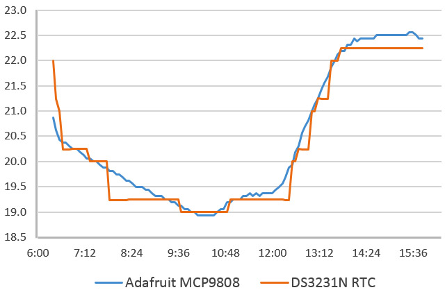
You can see that the DS3231 has a much lower bit depth, but I was pleasantly surprised by how closely they tracked each other. If the datasheet claims are to be believed, the 9808 should be dead-on in this temperature range. This gives me more faith in the data from that humble RTC, which currently records ambient temperature in my drip sensors.
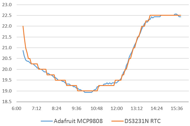
Addendum Update: Although I did not catch it when I posted this graph, I was converting the LSB portion of the temperature register with:
TEMP_degC = ((((short)MSB << 8) | (short)LSB) >> 6) / 4.0;
from Coding Badly at the Arduino forum. There should have been no “bumps” on that graph smaller than 0.25°C. But what I was actually getting a mix of xx.00, xx.25, xx.244 and xx.238 in my data. No half degrees, and no temps that read xx.75 You can see those temps are missing, as “steps” in that graph.
So I tried this code to fix that with this code from the Arduino forum:
Wire.beginTransmission(DS3231_ADDRESS);
Wire.write(0x11); //location of Temp register MSB, LSB at 0x12
Wire.endTransmission();
Wire.requestFrom(DS3231_ADDRESS, 2);
bytebuffer1 = Wire.read(); // Here’s the MSB which is an int
bytebuffer2 = Wire.read(); bytebuffer2 = bytebuffer2 >> 6;
// the upper 2 bits of the LSB represent quarter degrees 00=.00 01=.25 10=.50 11=.75
TEMP_degC = float(bytebuffer1);
switch(bytebuffer2){
case 0:
TEMP_degC = TEMP_degC + 0.00;
break;
case 1 :
TEMP_degC = TEMP_degC + 0.25;
break;
case 2:
TEMP_degC = TEMP_degC + 0.50;
break;
case 3:
TEMP_degC = TEMP_degC + 0.75;
break;
}
// see http://forum.arduino.cc/index.php?topic=262986.15 for temps below zero with no floats
But I got the same result with that code too which is very puzzling to me?? Where are the .238 fractional temperatures coming from? Why do I never see xx.5 or xx.75 temperatures?
Addendum Update Update:
So it turns out that both examples of code above work fine, but the way I was converting the fractional part of the decimal (so I could print them as integers: printing real #’s takes too much ram) was incorrect. All my other temperature sensors provide at least three digits of information after the decimal place so I had been using fracTemp=(TEMP_degC – wholeTemp) * 1000; to extract the fractional data. But this did not work for the RTC fractional data. Changing it to fracTemp=(TEMP_degC*100) – (wholeTemp*100); converts the decimal part of the RTC temperature into integer values normally. Thanks to Stack Exchange for showing me that you need determine exactly how many decimal points you want to turn into the integer before you do a conversion like this, or the calculation yields weird results. In my case the error changed xx.05 into xx.0244, and xx.75 into xx.238. Fortunately that error was correctable, so here is what that graph should have looked like:
Addendum 2014-12-20
Recent fieldwork gave me a chance to check clock drift on six loggers using these RTC boards. All of these RTCs were set at the end of August and over the course of about 4 months, all of them lost between 30-40 seconds. That puts these cheap units over the minute per year territory that I see claimed for “real” DS3231 breakouts like the Chronodot, but not by enough to make me worry too much as this was a pretty crude test. These modules are still far better than any DS1307 alternatives.
Addendum 2015-01-11
Obvious, I know, but it still took me ages to realize it…
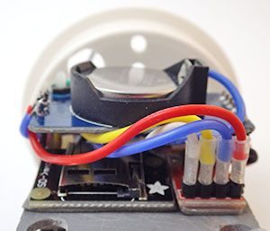
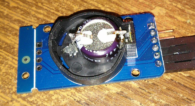
I have been putting together some smaller underwater sensors using two inch pvc pipe, and the tight curved profile of the housing forced me to flip the RTC over. As soon as I did this, I realized that I should have been mounting the RTC this way all along, as it makes it easy to replace the coin cell without undoing the nuts on the standoff bolts. And if I am going to be pin-powering the RTC, I will probably need to change those coin cells regularly. It also lets me use shorter 12mm standoffs and still tuck everything under the RTC.
Addendum 2015-01-22 Unix time for logging
Steve Hicks over at envirodiy.org has posted on how to convert the DS3231’s epoch time (ie: #number of seconds since January 1, 2000) into unix time and here they convert unix time into Excel standard dates with [=CELL/(60*60*24)+”1/1/1970″ note: you have to have the RTC set to UTC for this to work]. Using epoch time lets you store or compare times as a single 32-bit number (another conversion method here) rather that dealing with 6 numbers and details like the number of days in each month and leap years. A very handy tip. You can view a datalogger script example using long epoch = now.unixtime(); over on Github.
P.S. MrAlvin’s RTC library (a fork of Jeelabs RTClib) yeilds unix time with:
DateTime now = RTC.now();
followed by:
Serial.print(“Seconds since midnight 1/1/1970 = “);
Serial.print(now.unixtime());
But if yours does not, it is fairly easy to calculate an epoch time integer from the standard YY MM DD MM SS format, if you have your clocks set to UTC.
Addendum 2015-03-11 Monitoring coincell with a divider

The coin cell monitoring divider tucks nicely under the header pins, which I fold back in my builds for the small diameter housings. The two resistors take the voltage to 1/2 actual, as some of my coin cells read higher than my system voltage of 3.3v when they are new and have no loads on them.
I have decided to pin power all of my next generation of loggers, including the long chains of DS18b20 temperature sensors I have been working on. But I still don’t know exactly how much impact generating the interrupts will have on the coin cell over time, so I have added a voltage divider connected to the backup coin cell on RTC board, with the center drawn off to an analog input pin on the Arduino. I am hoping these 4.7 MΩ resistors will add only 0.35µA draw to the ground line and perhaps double that when the ADC input capacitor is being charged for a reading. The readings wobble a bit without a capacitor to stabilize them, but I was afraid that leakage on an MLCC would be larger than the RTC’s sleep current so I left it out. I read the pin three times with a 1ms delay, throwing away the first reading and averaging the next two, and that gets me a reading pretty close to what I see on an external volt meter. But CR2032‘s are lithium batteries, so I might need to put some kind of load on the coin cell to actually read it’s capacity. I was thinking I could do this by forcing a temperature conversion while the pin power is removed. (setting bit5 of reg 0Eh which draws 575 µA for 125-200 ms) This approach would waste some energy and create time delays, so I will do my first few test runs without the “load” to see if I can interpret the reading from that voltage divider without it.
Addendum 2015-03-13 Enabling Battery Backed Alarms
There is another question about pin powering these RTC’s that is niggling at the back of my mind: What happens when I have Battery-Backed Square-Wave Enable set with:
i2c_setRegisterBit (DS3231_ADDRESS, DS3231_CONTROL_REG, 6, 1);
so the RTC generates alarms when it is powered only by the backup battery, and then I disconnect power to the main Arduino before the next alarm? Presumably the alarm still gets generated, but nothing can respond and reset it. My hope is that the open-drain SQW pin, which should only sink current, does not somehow create a circuit through the Arduino that bleeds away power in this situation. Especially now that I have the voltage divider in place…?
Addendum 2015-04-01 Drift checks
To do the drift check, I screen grab the terminal window of a sketch that outputs the current RTC time with the windows system clock. Both are running UTC, and I make sure the computers clock was sync’d via web time servers.
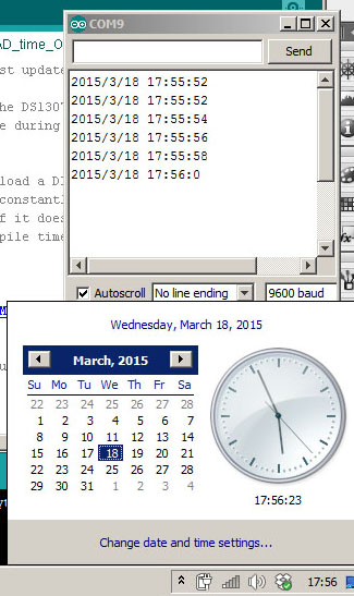
I just returned from another fieldwork trip, and I had the chance to do proper RTC drift checks on twelve data loggers that were deployed in Dec. 2014. After three months of operation they all had offsets between -24 to -30 seconds, and the remarkable consistency across these units made me suspect that I was looking at something other than random errors. I reset the clocks with the little netbook I had on hand, and re-checked the clocks. Sure enough every one of them was reading the current time -24 seconds. I checked the time on the six new new loggers that I had prepared before the trip and every one of them was exactly nine seconds slow (my computer back home is much faster than the netbook I take into the field). When I reset those new loggers with the netbook every one of them became 24 seconds slow. So it looks like the time lag caused by the compile & upload of the RTC set sketch was responsible for the majority of the offsets I reported back in December, and that these DS3234SN RTC’s actually have a drift somewhere between 0-5 seconds over a three month deployment. This is well within the manufacturers spec. And now that I know the compile time is the limiting factor, at least I can be certain that the units all have the same negative time offset before each deployment.
NOTE: With further testing I have found that if you simply hit the verify button before you hit the upload button, the resulting RTC time offset is reduced to 1/2 (or more for slower systems). On my home based system this reduced lag caused by the compile & upload from ~20 seconds to about 9 seconds. I expect to see even more of a difference on my really slow netbook. In theory you can improve things even more by removing the verify option as you upload. The RTC time setting sketch is the only place where I would risk errors to get to a faster upload time, since I immediately have to replace the RTC “setting” sketch with a “read time only” sketch to confirm it worked anyway.
Update 2016-10-14: I’ve been referring here to the setTime sketch that used to be provided with MrAlvin’s library. This sets the RTC to the compile time with the command
RTC.adjust(DateTime(__DATE__, __TIME__)); His new version has a method of setting the time using the serial monitor, which removes the compile time lag time problem. I’ve gotten used to using setTime & getTime , so I still keep a copy of those older utilities on my GitHub. Paul Stoffregens DS1307 library uses the same compile time method to set the DS3231, but you have to install his Time library as well.
The datasheet reccomends a delay before setting: “Communication with the I²C should be held off at least for the first 2 seconds after a valid power source has been established. It is during the first 2 seconds after power is established that the accurate RTC starts its oscillator, recalls calibration codes, initiates a temperature sensor read, and applies a frequency correction.”
Also worth noting Luca Dentella’s RTCSetup (compiled exe version –you need only RTCSetup.exe) that will automatically sync your RTC to the PC via serial if you already have Adafruits RTC lib installed.
Addendum 2015-04-05 Accidental High Temp Drift Check
Just digging into the recent data set, and noticed that one of the drip sensors we left out on the surface (to act as a rain gauge) got baked as the local climate went into the dry season:
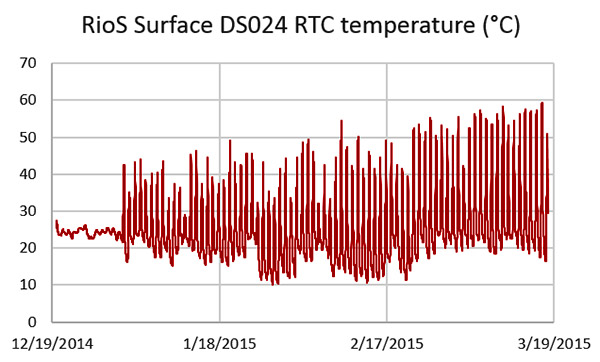
This is the record from the RTC, and I am surprised the batteries did not pop with the loggers internal temp hitting 60°C. The good news is that even after subjecting the RTC to this ordeal, the drift for this unit was the same as the units that were left down in the caves. This logger went back out for another stint in the tropical sun, as I am a firm believer in testing my builds to their limits.
Addendum 2015-04-07 Waking a logger with the RTC alarm
That last deployment saw several loggers run successfully with pin powered RTC’s so I though I should post the little code snippet I use to do that. I have the de-powering embedded inside the function that puts my loggers to sleep
In setup: (note brackets missing around includes!)
#include RTClib.h // https://github.com/MrAlvin/RTClib
#define RTCPOWER_PIN 7 // this is the pin I have jumpered to the RTC’s vcc leg
So after the setting the next alarm time in the main program loop
//The variables ALRM1_SET bits and ALRM2_SET are 0b1000 and 0b111 respectively.
RTC.turnOnAlarm(1);
I use this function to de-power the RTC and the data logger
{
//
#ifdef RTCPOWER_PIN //if using pin power on RTC, now depower it:
pinMode (RTCPOWER_PIN, INPUT);
digitalWrite(RTCPOWER_PIN, LOW);
// driving pin LOW FORCES to the RTC to draw power from the coin cell during sleep
#endif
//
noInterrupts (); // make sure we don’t get interrupted before we sleep
attachInterrupt(0,clockTrigger, LOW);
interrupts (); // interrupts allowed now, next instruction WILL be executed
LowPower.powerDown(SLEEP_FOREVER, ADC_OFF, BOD_OFF);
detachInterrupt(0); //HERE AFTER WAKING UP
//
#ifdef RTCPOWER_PIN
digitalWrite(RTCPOWER_PIN, HIGH); // about to generate I2C traffic
pinMode (RTCPOWER_PIN, OUTPUT); // so provide power to the RTC
#endif
//
}
and clocktrigger is the ISR that updates a variable checked in the main loop
clockInterrupt = true;
}
So there you have it. After 3 months of reliable operation, and no coin cells killed off in the process, I am calling this good. BTW this is how I currently connect the RTC boards to the Arduino:
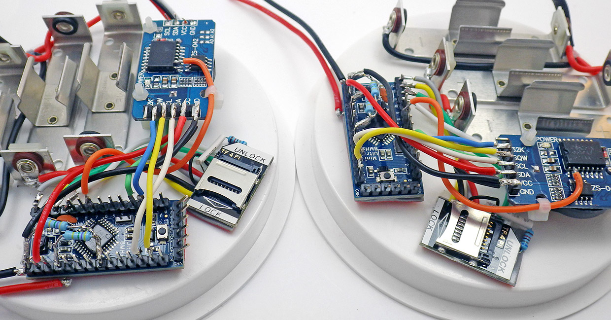
For more information on how I assemble these data logger platforms, see Sensors 2018: A Flexible Arduino-Based Logging Platform for Long-Term Monitoring in Harsh Environments [open access – PDF is free to download]
Addendum 2015-06-10 Running the I2C bus at 400khz
After finding Rob Tillarts multispeed I2C bus scanner, I was happy to notice that all my I2C devices showed up on the higher speed scans. So I have started pushing the bus to faster 400 khz speeds with TBWR=2 on the 8Mhz boards, and TBWR=12 on the 16Mhz boards right after Wire.begin(); The DS3231 is rated for it. The larger AT24C256 eeprom that I have been adding to my loggers is also rated to that speed, but even the smaller AT24c32 on the RTC board seems to work ok at the higher I2C bus speeds, though it is only rated to 100kHz. Since I had been using the I2C communication delays as part of my led pips, I could immediately see shortened operating time (my pips became too short to see) . I have some doubts about whether a humble 8Mhz Arduino can run the I2C bus that fast. Without a scope, or some way to determine the capacitance on the lines, there’s no way to know if I’m actually reaching 400khz with the 4.7kΩ pullups on that RTC breakout. But with quite a few run tests going well thus far, I think add the TBWR settings to my standard code build to shorten mcu up time.
Addendum 2015-06-17 Risking (?) Ultrasonic Bath Cleanings

Since these boards are always covered with flux, I picked up a cheap ($15) ultrasonic cleaner and used it on a batch of 12 of these boards with 90% Isopropyl alcohol. After the cleaning I put the used fluid in a jar, and this batch of goo settled out. I know that ultrasonic cleaning is very bad for oscillators, but flux corrosion is lethal too…
I have done a few more tests using a 2x 4.7MΩ divider to monitor the coin cell. The divider definitely works but as expected it also bleeds 0.32µA from the coin cell when the Arduino is powered & sleeping. If I remove power from the whole Arduino, the current drain from the battery through the divider rises to almost double that at 0.56µA. Pin Powering the RTC during uptime and letting it go into timekeeping mode (3 µA) while the Arduino sleeps (with the coincell divider in place) appears to be causing a 5-7mV drop per day on the CR2032 coin cell. With the 2300 mV minimum for the DS3232’s vBatt, that probably means the coin cells will only provide about 4-5 months of pin powering before the little cells need to be replaced. This is a somewhat irritating as I thought I would get more time than that from the 240 mAh coin cells. I am suspecting there are other drains occurring somewhere.
One trick I can try is to set the coincell reading analog pin to INPUT_PULLUP with a pinmode setting while the Arduino sleeps. This would raise the middle of the voltage divider to 3.3v – above the coincell. This will also send 0.7µA from the analog pin through the grounded leg of the divider. When I tried this I found that it also pushes about 0.03µA back towards the coin cell’s positive battery terminal where I have the divider connected. I don’t know if that power is flowing into the lithium coin cell (which is probably bad for CR2032’s – but perhaps it would be ok with an LIR2032?) or into the RTC somehow (?) So this strategy would shut down the divider power leakage from the coin cell and hand it off to the much larger main batteries. This is much lower than the 89µA that the RTC draws if you power it via the Vcc line, but it seems a bit dodgey to flip flop between analog and digital modes on that pin all the time.
I will have to do more tests before I trust that this is not hurting the RTC or the Arduino. Having the lithium coin cells catch fire when their voltage got low would not make my day either. And if I was going to have a small constant drain from one of the pins I might as well just replace the coin cell backup battery with a capacitor – which could be kept charged by the pin that I am currently using to check the backup battery voltage. That way I’d never have to worry about changing the RTC batteries once I got the system rolling…hmmmm…I wonder what the capacitor leakage current would be?
P.S. In my tests to date, the faster 400khz I2c bus settings settings still seem to be working OK.
Addendum 2015-07-23 Backup battery only power looks OK
Looks like my earlier concern about the new divider creating and excessive drain the RTC backup battery were unfounded. Several of my bench test loggers saw an initial drop off but all of them seem to have leveled out around a nominal 3.05 v.
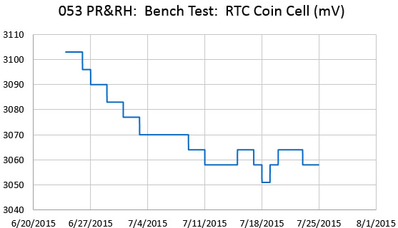
Most of the new batch have this 2 x 4.7 MΩ divider in place and I am now confident that it will be Ok to deploy those units, which likely will not be retrieved till the end of the year. Btw there is a fantastic page over at ganssle.com testing the behavior of CR2032 batteries at low currents. Granssle’s article on Issues in Using Ultra-Low Power MCUs is worth reading. Hackaday’s post on TI processors shows how far the art in low power operation goes. Ignoring self discharge, a CR2032 should be able to last about 4 years if the average draw stays below 5 µA, and the divider is adding ~ 0.7 µA to the RTC’s base load. Actually the DS3231 datasheet specifies the average battery current is less than 3.0 mico-amps, so a typical 200 mAh CR2032 should be able to supply that for about seven years.
Addendum 2015-10-30
Just a quick update on that coin cell reading. I continued that test (on a logger with 20 DS18B20 temp sensors) and the coin cell voltage rose after the break then fell again to about 3040mv:
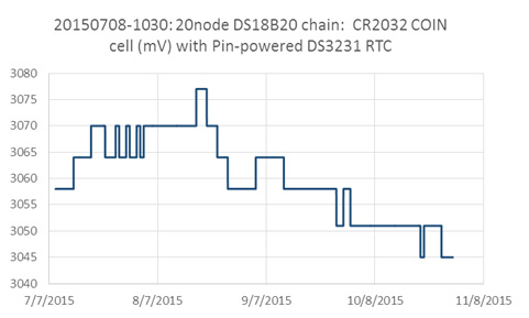
cr2031 voltage on pin powerd ds3231 RTC module data logger
So at least I am not seeing a catastrophic fail when trying to read the coin cell, but I am still left with the question of whether this reading actually means anything, given that the loading on these lithium cells is a mere 3μA when the RTC is in timekeeping mode. (If straight ADC reads don’t work, I might try the LED/resistor method so that the coincell is loaded during the readings) I still might be shortening the lifespan of my loggers below my one year target with the pin powering technique if the coin cells can’t go the distance. At 150-200 mAh /cell, there should be no problem…but I have made the mistake of counting those chickens before. And I still might need that 1µF cap across the lower resistor, which in theory will cost me ~1nA in leakage.
Note: Data from the batch of loggers deployed in Aug 2015 displays a similar pattern to my bench test results:

RTC coin cell (mV) record from a real world drip sensor deployment
All the loggers using 2×4.7MΩ dividers to track the coin cell leveled out somewhere between 3020 & 3040 mV, and I attribute the differences there to ADC & resistor offsets. So I will adopt this as a standard part of my new builds.
Addendum 2016-01-08
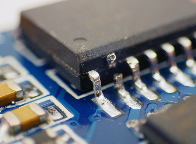
The most common manufacturing defect I see is IC bridged pads from bad reflow, but you also see tombstone errors like this on $1 eBay boards…
I prep these RTC’s in runs of 10 to 20 pieces, as this makes the best use of the isopropyl alcohol in the ultrasonic bath. While I was de-soldering resistors on the latest batch (to disable that useless charging circuit) I realized that the first part of the UNO based Datalogger Tutorial (that I put together to help some teacher friends of mine bring Arduinos into the classroom) gives you great platform for testing a bunch of these RTC’s quickly. You can just pop them onto the breadboard in quick succession before you invest any time cleaning them up. You don’t even need to put the battery in! And the code that I posted to Github for that logger is about the simplest example you are likely to find of how to use this RTC breakout to wake a sleeping Arduino.
Addendum 2016-01-16
Just stumbled across a post at Arduino Stackexchange on combining day-month-year data into strings, and using that as a date-stamp file name. This could be handy for “threshold/event” based loggers, as opposed to the more typical take a sample every X minutes approach. I think this method is limited by fat16 to generating a max of 512 entries in the root directory.
Addendum 2016-01-21
Data from a cave deployment of one of our multi-sensor units:
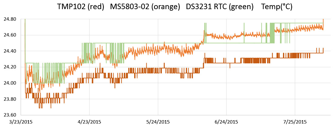
The MS5803 is a 24bit pressure sensor which has a metal ring in contact with the air, while the TMP is 12-bit sensor embedded under 3-4mm of epoxy, and the DS3231 RTC is inside the housing body
so I am impressed again with the temp accuracy of those humble RTCs. This is also a really great illustration of what you gain when you add more bits to your temperature record.
Addendum 2016-02-13
Over at raspberry-pi-geek.com they did some benchmarks with four I2C RTC’s: the DS1307, the PCF8563, the DS3231, and the MCP79400. Their graphs show the DS3231 as the overall winner, suggesting that this is is a result of the temperature compensation. It will be interesting to see if they do the tests over again with temp variation to see how this affects the RTCs accuracy.
Addendum 2016-02-26 Using a super cap for backup power?
One of Tominaksi’s photos of his retrofit. There actually are capacitors built to coin cell shape/size specs for this purpose over at Mouser, but they are not much larger capacity than the 0.22F he used.
Just stumbled across a playground forum thread where user Tominakasi tried replacing the backup battery with a capacitor . He reached 24 hours of operation with a 0.22F , but I would need significantly more time than that in a logger application. If I play with some datasheet numbers over at Maxim’s Super Capacitor Calculator, it looks like it might be feasible with a one farad cap. But folk’s over at Sparkfun, seem to think that leakage current would be a serious problem. Since I am already tracking the coin cell voltage with a resistor divider on the top of these boards, I think I will pickup a 5v 1F super cap and try an experiment to find out how long it actually takes for it fall to the RTC’s 2.3v minimum. It would not take much to connect one end of that cap to a separate digital pin and then top it up when necessary because the Arduino will keep a pin driven high even while sleeping. Probably not worth doing for a regular logger, but if I was building something completely potted in epoxy… hmmmm…
Note: HarryCh reports at the playground forum, a Panasonic EECS5R5H474 0.47F super cap charged to 3.3 v via the existing charge circuit, was able to power to the RTC chip for two days before falling to 2.21v, and four days before falling to 1.73V.
Addendum 2016-03-04
There must be a million great clock projects out there, but I stumbled across a couple recently that looked like they would be fun to build. The idea embedded in the Laser Cut Clock by [Buckeyeguy89] really has legs, and I think it could go on to some very interesting higher levels of complexity. And I am sure that I am not alone in drooling over the Ferrofluid Clock by Zelf Koelma, to the point of wondering how I could drive batch of small electromagnets with an Arduino…
Addendum 2016-04-07 Date your coin cell batteries
Another coin cell curve (mV) from a longer deployment:
Should have been doing this from the start…
This was from a 2×4.7 MΩ set, so I am more confident that we will go a year even with the added drain from the divider. I have since switched over to using 10 meg Ω resistors, but there is some question of whether the ADC sample & hold caps can will get enough current to read that properly. I’ve been dating the coin cells with a marker to help keep a tab on their lifespan.
Addendum 2016-04-21
Just had to post a link to the Arduino Sport Watch Instructable by Alexis Ospitia which combines this DS3231 board with a pro-mini and one of the ubiquitous Nokia 5110 LCDs.
Addendum 2016-05-21
There are a host of changes coming as the ATmega 328p becomes the 328pb. But relevant to this thread, the full-swing oscillator driver circuitry is being removed. While this won’t affect a low&slow application like data loggers, it might spur a few more people to look into the 32K output from these boards. If that’s your thing, there are some interesting frequency measurement guidelines over at sitime.com
Addendum 2016-05-18
Just had to add a shout out here to Luke Millers Tide Clock as a great use for the DS3231 breakout, and a great addition to his Open Wave Height logger project. There are only a handful of us focusing on underwater logging, and his work on the MS5803 was a great contribution.
Addendum 2016-06-13 Caps to buffer intermittent load on coin cells?
 I’ve been trying out some $2 coin cell testers from eBay, and so far they seem to be working ok. There’s a big logger service trip coming up, and this will come in handy.
Ti also has an interesting article on using caps to buffer intermittent loads powered by a CR2032. Coin cells: The mythical milliAmp-hour over at Hackaday goes into other details, with the takeaway being you should always let your batteries rest for 25 ms or more between load-pulses if you can. How much energy you really get from a coin cell depends on the maximum current you need to draw from it, and the DS3231 temperature conversion means the cell will see a pulsed load of 0.57mA every 64 seconds.
Addendum 2016-07-02 Excel Tricks for Time Series Data
Times in Excel are factional values of 24 hours. One hour of time is 1/24, and 1 minute of time is 1/(24*60) = 1/1440 – so always enter time increments ‘as fractions’ in the cell rather than numbers. There is an interesting time-related function in Excel that is really useful to know about if you are trying to isolate subsets from your time series data:
…use a helper column and then filter on the results of the helper column. Assuming your date/time record starts at A2, and column B is available, then enter the time interval you wish to filter on in cell B1 (e.g 10 or 30 etc). Then enter the following formula in cell B2 and copy it down the rest of the column:
‘=MOD(MINUTE(A2),$b$1)=0
This will provide a TRUE/FALSE value if the time conforms to the interval value contained in cell B1. Then filter all the records based on the TRUE values in column B.
I tend to run my bench tests pretty fast to give new builds a real workout, but then I end up with far more data than I need for calibration / normalization. This little trick works a charm to bring that back to more typical 15 minute sample intervals.
And while we are on the topic of time in Excel, it’s worth mentioning that the program sometimes refuses to convert time stamps from commercial loggers into its native number format. In that case you end up having to extract and convert each piece of text data with a =DATE(year, month, day) and =TIME(hours, minutes, seconds). As an example, converting some weather station times tamps that looked like this 01.01.2009 02:00 ended up needing this beast:
=DATE(MID(B2,7,4),MID(B2,4,2), LEFT(B2,2)) + TIME(MID(B2,12,2), RIGHT(B2,2),0)
If you google around you can find good guides explaining how to do that, but it’s still a pain the backside.
A much trickier problem is dealing with badly formed dates that are already in Excel’s native format. Aside from randomly missing data, the second most common problem with weather station data that you download from other sources is that the time serial number (where 2014-1-1 8:00 is actually stored as 41640.3333) has an odd rounding error or other random cruft somewhere down at the 9th decimal place. This will mess up any kind of sorting/comparing in formulas even if the dates are being displayed perfectly fine. The trick is to convert both sets of excel dates into plain text with B5=TEXT(C3,”dd/mm/yyyy hh:mm”), and then re-convert that text back into date & time as described above [with C5=DATEVALUE(LEFT(B5,10)) & D5=TIMEVALUE(MID(B5,12,8))] then concatenate them back together with =C5+D5. Then your hidden-flaw excel date serials, become perfect excel dates again, and all your sorting, etc. starts working again. Don’t forget to check for local vs UTC/GMT timestamps. If you need to add 6.5 hours to a time stamp, that’s done with =C5 + TIME(6,30,0)
Another common problem for loggers used in the field is when your RTC gets reset to the Jan 1st 2000 by a hard bump that momentarily dislodges the backup coin cell contact. You will know the installation date/time based on your field notes, but then you have to re-constitute the timestamps from scratch. The key to doing for long periods is not to use excels drag-fill feature as this will create substantial and ever increasing errors in the generated time stamp. Create the first time stamp ‘manually’ and then to add one minute to the previous cell, use this formula:=previous cell +1/1440, if you want to add one second to cell, use this formula: =A2+1/86400. There will still be a small rounding errors in each subsequently generated time stamp but using fractions will use all of the bits available to excel – so those errors will be small.
And since we are on the topic of useful Excel tricks, another one that is often needed with environmental data sets is determining local daily maxima values with multi-cell peaks. Then you can label those events in your time series. If you need peak detection of a time series to happen ‘live’ on your logger, then a modified median filter is the way to go.
Excel sometimes refuses to parse dates that arrive as ascii data from a datalogger, even when they are perfectly formatted. In situations where excel simply will not interpret timestamps that look like a ‘date’, sound like a ‘date’, and probably even smells and tastes like a ‘date’ – then try using a helper column with the formula =DATEVALUE(date_text) But hey, there are worse problems to have with excel…right?
Addendum 2016-08-03 Apple computers have no UTC?
I was showing a friend how to set the time this RTC recently, when we made the surprising discovery that you can not easily set the system clock on an Apple to UTC. You can select London, England, however England uses daylight savings time and as a result uses GMT (UTC+0) during the winter and British Summer Time (UTC+1) during the summer. (aka selecting London as the city to base my timezone does not provide UTC year round, only in the winter). A bit of hunting revealed that there are other cities in the GMT timezone that do not use daylight savings time such as Ouagadougou, Burkina Faso, and there are other fixes out there if you are willing to go under the hood. But its just hard to believe that Apple made it so hard to set a computer to the global time standard…weird.
Addendum 2016-09-09 Direct MOSFET power control by DS3231 Alarms?
 With long startup latencies & initialization issues in the SDfat library, I haven’t pursued approaches that remove power from my loggers between samples. But I’ve been reading about what might be the most elegant approach to the complete shutdown method for data logging applications: Using the RTC alarm (which outputs low) to control a P-channel Mosfet (AO3401) on the high side of the main battery supply. When the INT/SQW alarm goes low, it turns the mosfet on and powers everything including the main mcu board which would then goes to work taking samples and storing data. Then the final step after a sample is taken would be to re-program the time for the next RTC alarm, and then write zeros to the alarm flag registers (A1F and/or A2F) which would then release the INT line on the gate of the mosfet. (you would need a pullup resistor on the gate to make sure the pFet turned off properly). Geir Andersen discusses this over at LetsMakeRobots, and I think it’s the method that he used on the Deadbug shield. Even more interesting were hints that this approach was used with an ESP8266 to build a mains dimmer switch. Food for though, as I can see how stabilizing the Mosfet control line might be a little bit tricky, and in my case, the main battery voltage is higher than the RTC’s 5.5v maximum, so I would have to use a lower voltage battery as the main power supply.
Addendum 2016-12-31 More Drift Checks
I tweak the code on most of my loggers between deployments so often only the more unusual sensor combinations get run for long periods of time without a clock reset . The last round of fieldwork had me updating several of those old dogs, most of whom had been running for more than a year, and this let me do some RTC drift checks. There were two end members for the set; with one unit losing 1.1 seconds per month, and another gaining 1.4 seconds per month. Most of the other loggers drifted forward by ~ 1/2 second per month. So my two worst-case units have drift rates about twice as large as the 0.026 seconds per day they saw at SwitchDoc Labs, but most of my units are in good agreement with their benchmarks. HeyPete.com is doing detailed testing, and usually sees +/- 0.5ppm (~16 seconds a year of drift) which is less than the +/- 2ppm allowed in the spec. He has also de-capped a few of the chips, and verified that these cheap Chinese RTC modules are not made with counterfeit chips.
All of these loggers were in a very stable thermal environment (ie. a cave) at around 24°C. Depowering the RTC does not seem to increase the drift, (in fact David Pilling found that timekeeping on these boards actually improves when you disable the lithium coin cell charging circuit) and the coin cells look like they will last well past two years with this level of drain, but it’s still uncertain exactly when they will quit due to flat lithium discharge curve.
And while we have plenty of high-precision sensors for temperature data, the RTC registers continue provide a convenient ‘inside the housing’ record:

(The log shown above is from a very dynamic site with several entrances to provide airflow, but most of the other temp. records hover near the bit toggling point all year. )
While there is a lot of lag in the RTC temperature reading due to the thermal mass of the housing, these logs still provide a good sanity check when my other sensors are starting to fail.
Addendum 2017-01-18
Hackaday released a post on the quartz crystal resonators which provide the heartbeat for RTC modules and Kerry Wong demonstrates how to adjust the aging offset register with a HP 5350B in high resolution mode. The aging offset register is at 0x10 and the valid values for the parameter ranges from -128 to 127. That # is converted into 2’s complement before sending to DS3232. Each adjustment step changes the clock frequency by roughly 0.1ppm -which translates into roughly between 0.002 to 0.003 Hz. If I understand things correctly, the aging offset is most often used to correct problems with RTC that are running more slowly as they age, and that does seem to be the most common offset I observe in deployed units.
Adafruit has produced a DS3231 module, if you want something more compact than these cheap eBay units, without the EEprom.
Addendum 2017-02-15 Circular buffer on the EEprom
I just noticed that the RTClib from Adafruit supports the use of this RTC with an ESP8266, which will come in handy in future. And there is another library out that makes use of the eeprom on these boards for circular buffer logging. Given the limitations of the ESP, a combination of those two could prove very useful…
Addendum 2017-02-22 Update the alarm time using modulo
After looking at the old logger code I have posted on the projects Github, Mark Behbehani emailed more elegant way to update the next alarm time using modulo, rather a cascade of if statements:
The calling code:
pinMode (RTCPOWER_PIN, OUTPUT); // RTC vcc connected to this pin
digitalWrite(RTCPOWER_PIN, HIGH);
delay(15);
DateTime now = RTC.now();
SetNextAlarmTime(now); RTC.turnOnAlarm(1);
delay(5); //give the RTC a few ms to finish operations
pinMode (RTCPOWER_PIN, INPUT);
digitalWrite(RTCPOWER_PIN, LOW);
// (Current minutes + Sample time) % 60 will give min for next alarm
// then utilize mask bits to ignore Hours and days, set seconds to 00
// Bit 7 on (AM3, AM4) 0x0C 0x0D to 1 and only min sec match
// i2c_writeRegBits(DS3231_ADDRESS,DS3231_ALARM1_HOUR,1,Bit7_MASK);
// i2c_writeRegBits(DS3231_ADDRESS,DS3231_ALARM1_DAY,1,Bit7_MASK);
// Using the existing libraries you can call
// rtc.getA1Time(byte A1Day, byte A1Hour, byte A1Minute, byte A1Second,
// byte AlarmBits, bool A1Dy, bool A1h12, bool A1PM
// Pull in Day,Hour,Min,Sec
// For sec (or min) interval (Sec+intval)%60 for Hours sest (H+intval)%24
// Using AlarmBits X|A2M4|A2M3|A2M2|A1M4|A1M3|A1M2|A1M1 to set mask to ignore
// Update only variable of interest for secintval Sec, for min interval Min,s=00
void SetNextAlarmTime(DateTime now) { // this replaces my cascade code
RTC.getA1Time(Alarmday, Alarmhour, Alarmminute, Alarmsecond, AlarmBits, ADy, Ah12, APM);
if (SampleIntSeconds > 0){ //then our alarm is in (SampleInterval) seconds
Alarmsecond = (now.second() + SampleIntSeconds) %60;
// gives seconds from 0-59 sec e.g. 50s+15 = 65s 65 %60=5s
AlarmBits = 0b00001110; // set to ignore any match other than seconds
RTC.setA1Time(Alarmday, Alarmhour, Alarmminute, Alarmsecond, AlarmBits, 0, 0, 0);
}
else { //means seconds is set to zero and use SampleIntervalMinutes
Alarmsecond = 0; //force matching on even min
Alarmminute = (now.minute()+ SampleIntervalMinutes) % 60; // gives from 0-59
AlarmBits = 0b00001100; // set to ignore days, hours but match min, sec
RTC.setA1Time(Alarmday, Alarmhour, Alarmminute, Alarmsecond, AlarmBits, 0, 0, 0);
}
That’s the first time I’ve seen modulo being used, and I think it’s quite elegant. (with the quid pro quo that the modulus (%) operator is quite demanding on the 8-bit AVRs)
Addendum 2017-04-06
Following on that modulo comment, I came across a post using it to encode dates with only 7 alpha characters, as opposed to the standard 10 digits you would see with the ascii version of a Unixtime date. Of course, if you take samples at whole minute intervals, you can use Unixtime/(sample interval*60) with no data loss. If you take samples every 15 min, then you are dividing the unix time by 900; reaching the same 7 character size without any complicated algorithm.
Addendum 2017-04-11 Can I make diode-OR behavior?
I just noticed that Energisers CR2031 coin cell datasheet lists something interesting: Max Reverse Charge: 1 µA With the number of people warning about non-rechargeable cells exploding if you put them in a trickle charge circuit, I’ve simply been removing the charge circuit resistor. But with their 20-30 ohms of internal series resistance, I am now wondering if the relatively low 3.3v Vcc on my promini’s means that the voltage drop on the resistor & 1N4148 diode combination would give me enough wiggle room to keep the coin cell below that rev charge spec, while still supplying the 0.3µA timekeeping current to the RTC from the main AA batteries when that supply is available.
…Thinking about it a bit more, I guess what I am really after is a simple modification that provides a Diode-OR behavior to switch between the coin cell & the 3.3v rail on the chip’s Vbat line. If I cut the trace from the positive terminal of the coin cell and jumper a 1n5817 across to the common pad on the existing charger circuit, I think we would have the best of both worlds. There would be some drop across the 200Ω resistor & 4148 diode, so the 3.3v rail would deliver less than that to Vbat, and this would drag the coincell/shottky combination down, but once they equalize that the drain on the coincell should go to zero. Perhaps, I should add a little cap in there to smooth the voltage transitions?
Addendum 2017-04-15 Coin Cell backup routed through a diode
 I tested the 1n5817 Diode-OR idea: with 3.289v on the Vcc line from the Promini’s board regulator, the DVM sees a voltage of only 3.028 on the Vbat line, so the drop across the diode/resistor pair was 0.261v, which is pretty low for a 4148 because of the extremely small current flowing through it. My primary concern was that leakage through the Shottky would exceed the reverse current spec on the coin cell. So I put a very dead CR2032 in the RTC module (which read at 2.8v unloaded, so around 75% discharged) and that showed a steady 0.69µA of reverse leakage going backwards through the 1n5817 into the coin cell when the charger circuit side was powered. When I disconnected the main logger’s voltage
 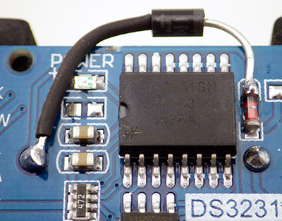 regulator, the current through that diode changed direction as it was supposed to, and increased to 0.84µA, which is less than the typical timekeeping current for these RTC’s, so the coin cell can’t be loosing much power to the main Vcc line by backwards leakage through the charger circuit. You could also clearly see the periodic current spike from the temp register updates when they occurred. After several power/depower cycles like this the RTC did not loose its internal time even with this crummy backup battery. Then I switched to a slightly less dead coin (at 3.08v unloaded which is still low) and the reverse leakage fell down to only 0.19µA. So a really low voltage coin cell will see some power flowing back into it, but both were below that 1µA reverse current spec.
Note that this whole idea assumes that you are providing pin-power to the RTC during I2C communications!
Switching to a brand new coin cell (read unloaded at 3.265v) and there is no reverse leakage when the loggers Vcc is powering the charge circuit, but a small forward current from the battery to the main pad of 0.01µA. The coin cell is now applying a higher voltage to the common pad than the 3.028 it would receive through the 200Ω resistor/1N4148 diode combination. So I think that a new coin cell will eventually be pulled down to match the charger pad voltage, but since the normal discharge plateau for Cr2032’s is at 2.9v, and the Vcc supplied pad stays around 3.03v, the coin-cell should never really have the opportunity to discharge if the logger is powered by the main AA battery.
WooT!
Addendum 2017-08-01 Other DS3231 breakouts
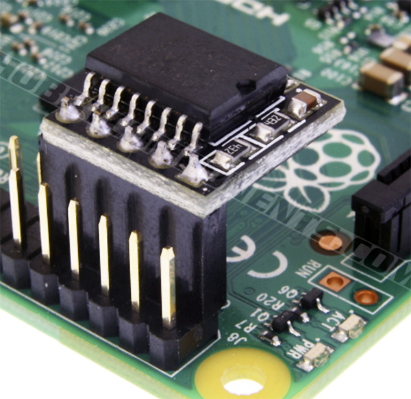 I’ve been noticing more DS3231 breakout boards on the market as this chip is also a go-to chip for the raspberry pi , but for some reason many do not have the alarm line broken out. This is a mystery to me as I don’t understand why you would leave that functionality out of a design? A lot of PCF8563 boards use this “no-alarm” format as well. Harald Sattler did some jumper conversions to fix this deficit on the Rpi RTC’s for his world clock project.
Addendum 2017-08-01 Accurate Drift test of these modules
Looks like heypete is at it again with some serious drift testing of these RTC’s. I’m already convinced these cheap modules reach the bar for environmental data logging, but clearly that’s not good enough for a physicist. I’ll be keen to see his results. (Addendum: HeyPete just posted some 5-month test results: Five of the seven crystal-based DS3231 chips ran fast, while two ran slow. All three of the MEMS-based DS3231M chips ran slow. However all of the units were withing the spec for the respective chips: +/- 63 seconds per year for the DS3231SN, and +/-2.6 minutes per year on the -M variant ) If you want the highest accuracy out of these chips in your own design, it’s worth knowing that high frequency noise from I2C (for example) can couple to the internal crystal oscillator making the RTC run fast. Because of this the datasheet warns that you should avoid running signal traces under the package unless a ground plane is placed between the package and that signal line. Sattler also has some doubts about the buffering on those cheap knock of boards, which may make them susceptible to more direct interference from I2C coms.
Addendum 2018-02-04: Measuring Temperature with Two Clocks
By comparing a 1 Hz pulse from the DS3231 to the number of system clock ticks on a Pro Mini clone, I was able to measure temperature to a respectable ±0.01°C. I can also compensate for drift in the frequency based temperature using the temp. register on the RTC. Not bad for a method that relies on nothing more than a couple of code tricks.
At the other end of the spectrum, the DS3231 can also output a 32.768 kHz signal. This can be used to create accurate sub-second intervals by connecting that pulse to the XTAL1 input on the 328P, and then you sleep the cpu until the TIMER2 rolls over. Timer2 is only 8-bit, but by changing the prescaler value and the preloaded count you can set the period at which the interrupt fires to suit your project’s needs. Also, if you wanted a larger interrupt period, you can experiment with Timers 1,3,4, and 5 which have a 16-bit width and can count up to 0xFFFF, 65535 decimal. Just be sure to note which pins they are tied to
Addendum 2018-03-30 Grounding the VCC line, Adding a stabilization Cap
I made an error during some recent run tests, where I forgot to connect the RTC’s Vcc line jumper to the digital pin for power (see addendum: 2017-04-15) . The test ran without a hitch for several days (>6000 RTC temp readings & alarms) with the Vcc pin left floating, and power provided only through the Vbat line. I had assumed that high-speed I2C communications would fail in this situation, but after digging through the data sheet – it turns out that the DS3231 is fully functional on Vbat. With this realization in mind, I have changed the way I modify these RTC boards for low power sleeping:

Power LED disconnected & trace between Cr2032 & Vbat is cut. Positive coin cell post is then re-connected to Vbat through a 1N4148 diode, Vcc pin on DS3231 is disconnected from the board and re-connected to the common ground via one leg of the capacitor. The 0.1uF cap runs between GND and the Vbat line. With the board configured this way, the module’s sleep current is <1 µA when the I2C signal clock stops (with periodic spikes up to the 575 µA temperature conversion current). That sleep current is drawn from the main power rail via the old “charging” circuit diode, so the Cr2032 coin cell should not discharge at all when the logger is powered.
I had initially used the Shottky diodes because of their “instant” switch-over, but their leakage current is on the order of two to three times higher than with ‘normal’ diodes. And the Shottky’s lower voltage drop was forcing the RTC battery to discharge down to the voltage created when the 3.3v rail passed through the 200 ohm resistor & 1N4148 on the module’s charger circuit. (this pass-through is ~2.97v) By using another 4148 on the coin cell, with it’s matching 0.3v forward drop, I could preserve the coin cell battery at it’s higher nominal starting voltage. The DS3231’s Vcc pin is now connected to GND, rather than being tied to a digital pin on the Arduino for power during logger run-time operations.
I’ve added a small cap because memory within the DS3231 is susceptible to corruption if the VBAT line becomes unstable, which typically happens when removing or inserting the battery. The datasheet states to either change the battery when VCC is providing the power, or to use a capacitor on the VBAT line, to protect against that switch-bounce type noise when changing the battery.
Of course, If you wanted to live dangerously and leave that Vcc leg floating (…like I did by accident – and it still worked in a noisy urban environment…) the bare minimum low-power mod would be to simply flick the charge circuit’s 200ohm resistor off the board with the tip of an iron and then snip the Vcc leg with some side cutters. The RTC would probably still get you 4-5 years of operation running full time from the CR2032 ( or you could try to stuff a 600mAh CR2450 in there… ) Coin-cell holders occasionally lose contact very briefly under vibration, so if you cut the Vcc leg – put a .1 μF capacitor across the coin-cell holder. That value of capacitance will give you about 80 ms grace, which should be longer than the holder will lose contact.
Addendum 2018-05-16
I found an interesting note about errors caused with RTC communication if the Arduino suffers a voltage brown-out during coms when the DS3231 is in battery backed operation (which I am now using with the board modifications described above…)
Reliable Startup for I2C Battery Backed RTC: Why the Arduino Wire library is not enough
“The I2C interface is accessible whenever either VCC or VBAT is at a valid level. If a micro-controller connected to the DS3231 resets because of a loss of VCC or other event, it is possible that the micro-controller and DS3231 I2C communications could become unsynchronized, e.g., the micro-controller resets while reading data from the DS3231. When the micro-controller resets, the DS3231 I2C interface may be placed into a known state by toggling SCL until SDA is observed to be at a high level. At that point the micro-controller should pull SDA low while SCL is high, generating a START condition.”
Matthew Ford describes an I2C_ClearBus() method to deal with this situation which requires disabling the I2C interface.
“Communication with the I²C should be held off at least for the first 2 seconds after a valid power source has been established. It is during the first 2 seconds after power is established that the accurate RTC starts its oscillator, recalls calibration codes, initiates a temperature sensor read, and applies a frequency correction.”
Addendum 2018-05-16 The ‘-M’ variants of this chip are kind of lame
I just received another batch of these boards with the DS3231M ±5ppm MEMS oscillator (±0.432 Second/Day =157.68 seconds per year ) rather than the DS3231SN ±2ppm shown in the photos for the eBay listing. This kind of bait-n-switch is very common with grey market electronic parts vendors from China, and as heypete describes there is a significant difference between the two chips. Aside from the accuracy differences, the DS3231N/SN version can be used as both an RTC and a TCXO but the DS3231M is only an RTC. This means that the N/SN chips can output one of several temperature compensated frequencies on the INT#/SQW pin, but the DS3231M can only output a 1 Hz signal. In theory the MEMS version has better shock/impact resistance, and that’s actually a factor for some of our more rugged deployment locations. So despite my reservations about the lower accuracy, we might actually have a use case. There’s a few other quirks with the -M chip.
Another thing that rears its head is the issue of ultrasonic cleaning. These cheap RTC boards always arrived covered in flux, and that’s unlikely to be no-clean type stuff. I’ve been taking the risk of cleaning the RTC’s with 90% iso in a cheap little jewelry cleaner knowing that I might be harming the oscillators, but after more than 150 loggers, over 4 years, I’ve only had one confirmed RTC failure. MEMS are another big no-no for ultrasonic cleaning and who knows if the cleaner will hit a resonant frequency for that new oscillator…I probably need to start cleaning these boards by hand…
Addendum 2018-06-22
Spurred on by a visiting researcher curious about adding Cave Pearl loggers to their curriculum, I finally put together a set of video tutorials for the current build. Included in the set was a clip showing how I do the low power mod for the RTC board:
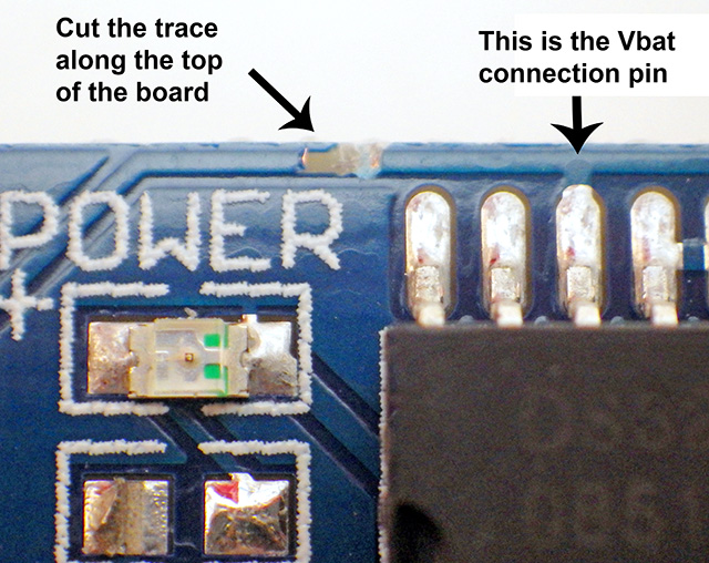
Addendum 2019-01-10 You DON’T need to ground Vcc! – JUST CUT THE LEG!
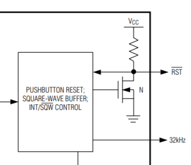
RST Pin I/O Leakage: -200 to +10 μA (high impedance)
Just thinking some more about that RTC module which ran despite the fact that the VCC line was completely disconnected…
A bit of digging in the datasheet finds:
The RST pin is an Active-Low Reset pin. This pin is an open-drain input/output which has an internal 50k pull-up resistor to VCC. No external pull-up resistors should be connected. (and that’s exactly what I find on this DS3231 breakout module: the RST pin is not connected to anything)
The same pin, RST, is used to indicate a power-fail condition. When VCC is lower than VPF (2.45 to 2.70v) an internal powerfail signal is generated, which forces the RST pin low. When VCC returns to a level above VPF, the RST pin is held low for tREC to allow the power supply to stabilize.
Assertion of the RST output, whether by pushbutton or power-fail detection, does not affect the internal operation of the DS3232.
The I2C interface is accessible whenever either VCC or VBAT is at a valid level. (Active Battery Current at 3.3V is 80μA, Timekeeping Battery Current, SCL = SDA = 0V is 3uA)
The oscillator does not start up and no temperature conversions take place until VCC exceeds VPF OR until a valid I2C address is written to the part. The oscillator may be disabled by setting the EOSC bit.
It’s worth noting that while the DS3231 can be set to generate time alarms while running from the backup battery, it can not drive any pulsed frequency outputs after this. Setting bit 3 of the status register to zero disables the 32k out.
So what it looks like is an “unconnected” Vcc pin triggers the power fail condition when the backup battery is inserted, but the VCC leg does not “float” because the RST pin is held low by the powerfail condition and the two are linked by an internal 50K resistor. The clocks oscillator can still be started by an I2C bus call, which you have to do to set the time anyway. So if you are OK with simply running down the CR2032 battery (which should run for months with an infrequently pulsed 80uA load during the I2C comms…) – then you don’t need to go through the extra circuitry I described above: you can simply kick off the smd resistors, cut the Vcc leg – and you have an RTC module that is pulling no power at all from the main power supply!

Loggers built with the Vcc leg cut – but not grounded -through the capacitor (shown in the video) have been operating normally . . .so far . . .
I will probably still keep using the more complex dual-diode mod, because field loggers sometimes take a beating on the way into a deployment, and I don’t want the time getting reset due to those hard knocks which are sometimes hard enough to dislodge the Cr2032. But for units going into more gentle environments, I think I will simply cut the Vcc leg right at the start, and live with the ~4-year lifespan on that backup battery. Also note that you need to set a register to enable alarms when running from backup power.
NOTE: Dec 2020: I’ve now done this diode & cut vcc mod to more than 100 deployed loggers. They have all been running fine! However there is one thing that’s worth mentioning again. You need to clear the status register in setup or the RTC draws excess current after the mod:
void clearClockTrigger()
{
Wire.beginTransmission(0x68);
Wire.write(0x0F);
Wire.endTransmission();
Wire.requestFrom(0x68,1);
Wire.read();
Wire.beginTransmission(0x68);
Wire.write(0x0F);
Wire.write(0b00000000);
Wire.endTransmission();
}
Addendum 2019-01-15 Direct power control via MOSFET & Ds3231 Alarm
Back in 2016-09 I mentioned that some projects were using the RTC alarm (which outputs low) to control a P-Fet on the high side of the main power supply. A very interesting instrument paper was recently published that uses exactly that strategy with a Wemos Lolin D1 Mini:
Measuring microenvironments for global change: DIY environmental
microcontroller units (EMUs). Mickley JG, et al (Methods Ecol Evol. 2018;00:1–7. https://doi.org/10.1111/2041-210X.13128)

A snippet from their schematic at: https://github.com/mickley/EMU/blob/master/Documentation/Diagrams/EMU%20v1%20fritzing%20schematic.pdf
The ESP8266 outperforms our humble Pro Mini’s with a higher CPU speed (80 Mhz vs. 16 Mhz), more RAM (43 KB vs. 2 KB), built-in WiFi, and more flash storage space (512 KB–16 MB vs. 32 KB). The whopping storage space options are especially attractive given that a typical deployment for us only generates about 4Mb of CSV data per year. But it has one big Achilles heel: the sleep currents are considerably higher, with the D1 Mini weighing in around 100uA. To put that in perspective, you can usually get promini boards down to about 5uA without much effort (and ~20 uA for the entire logger if you switch the SD card). To address this issue, the EMU project successfully implemented a high side switch with an NDP6020P, and documented the project on one of the best project Github Repo’s I’ve ever seen for an open source project. What’s interesting about their method is that the DS3231 is automatically powered by the AA battery whenever the system is “on”, so the backup coin cell should last for years…unlike the “simply cut the vcc leg” method I discussed in my last update. The potential 6v+ from that 4xAA is above the Ds3231’s rated max of 5.5v. But hey – they ran those loggers for months without that addition, so theres clearly a lot of latitude on the spec. There’s also the fact that I typically see a 300mv drop on alkaline batteries under load, so there’s a good chance that the RTC wasn’t over rating very long on their deployments.
Addendum 2019-03-03 32khz output can be used to measure temperature!
I recently did some experiments pitting the internal WDT against other clocks to see if it could be used as an ambient temperature sensor. In one of those I tried counting the 32khz output from the DS3231 as a trusted time base. It ended up being too slow for the job, but I figured I would add the enabling code here for future reference:
Wire.beginTransmission(0x68); //Tell devices on the bus we are talking to the DS3231
Wire.write(0x0F); //#define DS3231_REG_STATUS (0x0F)
Wire.endTransmission(); //Before you can write/clear the alarm you have to read the flag
Wire.requestFrom(0x68,1); //Read one byte
bytebuffer1=Wire.read(); //existing status register content bool 32kHzenabled=true;
bytebuffer1 &= 0b11110111; //clear the third bit
bool kHzenabled=true; //When set to logic 1, the 32kHz pin is enabled and outputs a 32.768kHz
bytebuffer1 |= (kHzenabled << 3); //writes third bit to 1 for enabled
Wire.beginTransmission(0x68); // talking to the DS3231
Wire.write(0x0F); //Status Register //Bit 3: zero disables 32kHz, Bit 7: zero enables main osc.
Wire.write(bytebuffer1); //Bit1: zero clears Al2 Flag (A2F), Bit0: zero clears Al1 Flag (A1F)
Wire.endTransmission();
Note that you CAN NOT do this trick with the -M variant of DS3231 because the MEMS itself is not temperature compensated the same way as the -S/SN variants.
Addendum 2019-03-10 Threw a bunch of -M modules in the garbage
Well it finally happened: I got a bad batch of the DS3231 modules -> all with the crappy -M version of the chip. (The “M” types have a MEMS resonator as a frequency-determining element on board,the others run with temperature-compensated crystal oscillators) The supply of -SN chips that have been on the market for years seems to have dried up for now, but of course all the eBay sellers are careful to only show photos of the -SN, and then ship you the -M. They know exactly what they are doing. About 50% of this bad batch have temperature register output that’s 5 to 10C above actual making me wonder if there is an internal current leak causing self heating. The ±2ppm of the SN chip is achieved by correction of the oscillator based on the temperature. With offset temp. register data I expect these defect boards to drift quite badly – probably approaching the ±20ppm errors you see on the uncorrected 1307 chips, which translates into about a minute of drift error per month. I’ve never had a problem with the -SN labeled modules, so for now I’m just throwing the suspect -M chips in the trash. The problem is that eBay vendors are notorious for using re-labeling chips, and I’m sure that there are some willing to print -SN labels on crappy -M chips. If you think you’ve got a re-tread try turning on lower frequency output, as the the M does not support 8k, 4k, or 1k.
And that makes me think some more about how to re-synchronize loggers that have been in the field for a long time. Best idea I can come up with is to have a “sync transmitter unit”, with a GPS to set its internal time, which then pulses out an (IR?) signal that triggers an incoming interrupt on multiple receiving units at the same time. This way I could bring wayward loggers back into time sync without physically disturbing them…? Have to put some more thought into this because if I was going to go to that level of trouble I might as well just configure an optical modem downloading unit to retrieve the data at the same time.
Addendum 2019-07-29 Tweak Aging register to GPS signal?
On this GPS and Time post, David Pilling use the analogue comparator to pit his UBLOX GPS against the DS3231 RTC – measuring the time between output edges (PPS from the Ublox on input0, and PPS from the DS3231 on input1) in msec. He then tweeks the aging register in the DS3231 to make it keep pace with the GPS, which is much cheaper than the Kerry Wongs method with a HP 5350B. GPS disciplined oscillators have been a thing in the amateur radio world for a while. TimeGPS from the Arduino Time Library by Paul Stoffregen is also worth investigating. If it was me, I want to parse the NEMA datat to do an initial date/time setting, then I’d probably have tried a counter on the DS3231’s 32kHz output, till the 1 PPS signal from the GPS triggered a second interrupt.
One thing to note here: the ‘time-nut’ sites claim that GPS pps can have pretty poor short term stability, though it has near perfect long term stability. So you can’t just sit there watching a single PPS and make adjustments to the clock crystal every second because it will jitter all over the place. You have to average out the jitter over a very long time constant (like one hour?) and have a good algorithm to make correct adjustments to your RTC oscillator at that point. A bit of code that did this automatically, say over a day of unattended operation would be a sweet little utility for users of the DS3231.
Addendum 2019-08-01 Clocking the Pro Mini from a crystal
Have a few project ideas that will need very accurate timing, so have been looking into clocking the Pro Mini boards from a crystal. The basic procedure for more accurate time with an Arduino follows the same steps:
Get a 32768 Hz watch crystal: either buy it or disassemble an old clock. These crystals, specifically designed for time keeping, have an extremely small temperature drift. You would also need one of those if you wanted to use an RTC chip.
Configure the fuses of your ATmega to run off the 8 MHz RC oscillator. This will make your millis() function horribly inaccurate, and also free the XTAL1 and XTAL2 pins.
Connect the watch crystal to the TOSC1 and TOSC2 pins. These are the same pins as XTAL1 and XTAL2 (9 and 10 on the 328P). The different names are used to mean different functions.
Configure the Timer/Counter 2 for asynchronous operation, normal counting mode, prescaler set to 128, and enable the timer overflow interrupt.Now you will get a TIMER2_OVF interrupt at a very steady rate of once per second.
David Piling and Jeelabs have both experimented with this procedure. But since the DS3231 is already temperature compensated, I just can’t help feeling there must be an easier way to do this using the DS3231’s output…
Addendum 2019-10-01
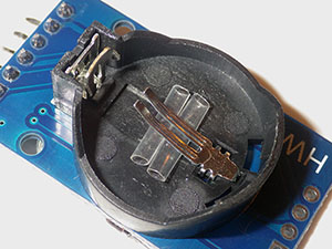
Soft 1.6mm heat-shrink behind the contact spring

Two dabs of hot glue.
I’ve been having the occasional bump reset on RTC modules running entirely from the backup battery (because the Vcc leg on the chip has been cut) . Not surprising given how roughly they get treated on the way into a cave, but I’ve recently started adding some re-enforcement to the coin-cell holder, which can be quite loose on some modules.
Addendum 2019-10-01
Here is an interesting article by someone who found that repeated access to the DS3231 registers over the I²C interface was slowing down the RTC because the knock-off modules do not double buffer the time registers (which would allow the clock to continue internally during a read access via I²C, undisturbed) I’m not sure I’ve seen any evidence of this with data-logging applications, which at a typical 15 minute sampling interval would probably fall into the bucket of a ‘low communications load’ application.
Addendum 2020-08-25
Well, it looks like the DS3231-S/SN has been discontinued and is not available for purchase from Maxim. This probably explains why they’ve been so cheap on eBay lately. Might have to take another look at the PCF2129.
Addendum 2020-10-15
This years student logger tutorial, showcasing this RTC module in context:

Logger assembled from off-the-shelf modules with minimal soldering.
Addendum 2021-01-25 External Interrupts can skip the ISR on Wake from SLEEP
I’ve spend the last few days trying to understand some pretty mysterious lock-up errors using BOTH external interrupt sources to wake our loggers from successive sleep events. The first source was a TTP233 cap switch and the other was the normal DS3231 interval alarm. The idea was to have the cap switch enable the display ‘at any time’ to show the recent sensor readings for 8 seconds while the RTC triggers the normal ‘full cycle’. Running both interrupts simultaneously (and leaving them engauged after waking from sleep) has caused several different lockup and/or endless restart loop failures but I think I’ve finally figured out one root cause and it’s related to how the oscillator’s startup latency on 328p based boards can lead to ‘orphan’ bits in the External Interrupt Flag Register (EIFR) when waking from deep sleep states.
From RocketScreams github:
“If your source of wake up has a very short pulse (example your low pulse from UART) even in the range of ms, the MCU will not be able to determine what woke it up because upon waking up there will be a delay due to oscillator start up sequence (configured using the fuse and how long depends on the fuse settings). By the time the oscillator start up delay has been completed, your signal has probably already went HIGH. So, this causes it to skip your ISR function call where you would set the IntFlag.”
Those latency delays are about 1msec on 16mhz boards and about 2msec on 8mhz ProMinis (+ disabling BOD before sleep adds another 60 uS) . The wake-up source needs to stay active for some number of CPU clock cycles after wake-up, and these clock cycles do not include the “1k clocks + 60ms” or whatever the fuse setting is. When you assert an interrupt, the device starts to wake up immediately, but it doesn’t follow the normal interrupt behavior until after the startup delay. If the interrupt source goes away before this time, the results appear to be undefined. Sometimes it will wake but you’ll get multiple interrupts, sometimes it will wake but be unable to read its own registers, and sometimes it won’t wake at all. (datasheet sec.17)
In my case the combination of waking the processor from two different external interrupts with the LOW condition for the RTC (ie: what I normally use) and FALLING from the TTP233 switch also caused some kind of pin13 flashing restart loop. LOW/LOW causes a hard freeze. Switching them both to FALLING got things running together.
Using the LOW ttp & LOW rtc combination does not work because the TTP is running in ‘momentary’ mode – so the ttp LOW condition disappears before the Arduino wakes up and this usually causes a frozen fail. FALLING ttp & LOW rtc generally ends up in a loop pulsing the pin13 LED which I think means that interrupt recursion is leading to some kind of stack overflow (?) = restart condition. Level interrupts continually fire while the condition is true and this can easily blow the stack. D2(int0) always gets serviced before D3(int1) because it’s the “higher priority” interrupt in the system – in fact it’s second only to the hard reset. (NOTE: Even in cases where you are not sleeping the cpu like I am – if high priority interrupts start occurring faster than the handler can service them, you get all the registers pushed onto the stack, which fills up & the cpu goes bonkers.)
FALLING ttp (int1) & FALLING rtc (int0) seems to work in every code combination with the interrupts ‘left running all the time’. The short duration of the trigger event prevents the stack overflow because it can only trigger ‘once’ AND because the second sleep library call forces the cpu deal with any EIFR flag bits that were orphaned by the first ‘slow-waking’ event. The sleep library does this because it puts the processor back to sleep with a sequence: noInterrupts() … more commands … interrupts(); sleep_cpu(); That global disable/re-enable forces the processor to check the flags and run any matching ISRs – which is the process that ‘normally’ clears those EIFR flags in a processor that’s not sleeping.
I brought this problem on myself by trying to keep the hardware interrupts going all the time for instant response. If you only enable LEVEL interrupts ‘just before’ sleep and then disable them ‘immediately after’ wake then the stack overflow problem doesn’t occur:
do {
oled.ssd1306WriteCmd(SSD1306_DISPLAYON); //switch display ON
attachInterrupt(digitalPinToInterrupt(capTouch_InterruptPin),switchPressed_ISR,FALLING);
attachInterrupt(digitalPinToInterrupt(rtcAlarm_InterruptPin),rtc_d2_ISR_function,LOW);
LowPower.powerDown(SLEEP_8S, ADC_OFF, BOD_OFF);
detachInterrupt(digitalPinToInterrupt(rtcAlarm_InterruptPin)); //detach higher priority 1st
detachInterrupt(digitalPinToInterrupt(capTouch_InterruptPin)); //detach lower priority 2nd
oled.ssd1306WriteCmd(SSD1306_DISPLAYOFF); // switch display OFF
attachInterrupt(digitalPinToInterrupt(capTouch_InterruptPin),switchPressed_ISR,FALLING);
attachInterrupt(digitalPinToInterrupt(rtcAlarm_InterruptPin),rtc_d2_ISR_function,LOW);
LowPower.powerDown(SLEEP_FOREVER, ADC_OFF, BOD_OFF);
detachInterrupt(digitalPinToInterrupt(rtcAlarm_InterruptPin));
detachInterrupt(digitalPinToInterrupt(capTouch_InterruptPin));
}while(rtc_d2_INT0_Flag == false); // if rtc flag not set (happens inside ISR) do the loop again
You still have to be carefull about not setting the momentary inputs like the TTP233 to LOW level triggering, or you get the orphan flag problem.
Addendum 2021-03-19
An interesting post on creating Optimal Timestamps for Bio-loggers. Our loggers buffer data to the RTC modules eeprom first AND we use fixed time intervals. So we’ve switched over to simply saving a ‘complete record’ – including the current timestamp – at the start of each buffer filling cycle, and then use the eeprom memory location of each successive record as the ‘time offset’ from that initial absolute value. A Unix timestamp for each record gets ‘re-constituted’ when the eeprom buffer is read back & transferred to the SD card. Note that all calculations for Unix timestamps have to be done with the compiler forced into ‘long’ uint32_t calculation mode by attaching an ‘L’ suffix to your constants. Othewise the compiler might switch back to it’s default int16_t calculations which will overflow. If you see your timestamps randomly increasing & then decreasing, you have a overflow error.
This method dovetails with the limited 30-byte data package of the I2C wire library; wherever possible you want to avoid having to make room for that timestamp in addition to your data. It’s worth mentioning that eeproms are pokey and do use a significant amount of power over time, so the only thing that makes it worthwhile to do this kind of buffering is SD card have high sleep currents & use absolutely ridiculous amount of power when cards trigger their internal housekeeping routines. Long-term logger solutions need to power the SD cards as rarely as possible.
Addendum 2020-05-24: Interrupt latency with wake from sleep
I just watched an interesting video about the sleeping the ESP32 processors and was quite surprised to find out how long (150 µS) and how variable the hardware interrupt latency is on these expressive processors. This set me down the rabbit hole to find out what the latency is on the AVR processors. On a normally running processor you enter the ISR in 23 clock cycles, which is about 1.5µS @16MHz. However if you loop through POWER_DOWN there are extra things to consider like the fact that disabling the BOD in software (just before sleep) is going to add 60 µS to your wake-up time. You also have an ‘oscillator stabilization period’ of 16k CPU cycles with a standard external oscillator. [see Sect.10.2 of the datasheet] The net result is that the Wake/Start-up time for a 8MHz Arduino is ~1.95ms. AVR’s with 16MHz clocks like the one I used for this test should have a wake-up time of less than 1ms. A 3.3v Pro Mini based build @8MHz is even slower unless you use SLEEP_MODE_IDLE to keep the main oscillator running which avoids that long stabilization delay.
Addendum 2023-12-01: 2-Part Pro Mini & RTC data logger
Anyone reading this post might find the latest iteration of our 2-Module Classroom Data Logger interesting as we power the unit entirely from the coin cell on the RTC module. The combination of a cheap ProMini clone with this RTC sleeps well below 5uA, and should easily run for more than a year on that Cr2032.

Adding a 32k eeprom to that logger is effortless with with the mini breadboards. But for those wanting a more advanced single-sensor build: In this video we walk through removing the default 4k EEprom on the RTC module and replacing it with two stacked 64k EEproms.
Addendum 2024: Calibrating & Synchronizing RTC time with a GPS
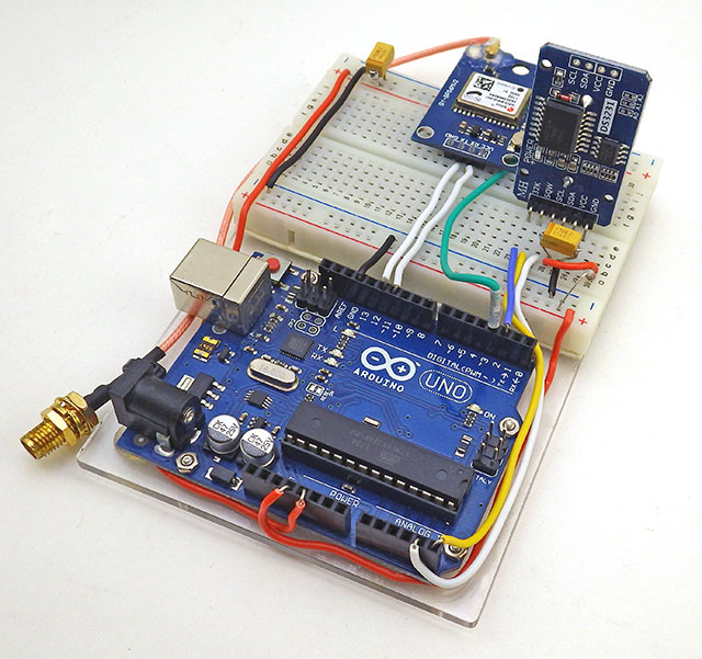
I finally addressed the issue of synchronizing multiple RTCs – primarily for better tide signal analysis but also because the quality of the chips in circulation seems to have fallen significantly since the beginning of this project. Taking a lesson from HeyPete (and others) we tune the aging register, and then set the RTC time from a GPS pulse which is usually within 100 nanoseconds of actual. With this calibration you should be able to reach 1-2 seconds per year with one of these RTC modules indoors.
See that new post at:
Setting Accurate RTC time with a GPS & the DS3231 Aging Offset to Reduce Drift

hi, thanks for the article. A few questions for you. When the DS3231 module is in timekeeping mode , does INT line still work (assuming it is pulled high elsewhere and not Vcc as described in the spec sheet)
We are trying to see if it is possible to use the interrupt line to turn on microcontroller (arduino)
while ds3231 is in timekeeping mode.
thanks
Yes. I still use the interrupt from timekeeping mode to wake my sleeping Arduino which then drives a pin high to apply power to the DS3231’s VCC input only when the MCU is awake. Before the logger sleeps again, I pull that power pin low to force the RTC back into timekeeping mode. The caveat here is that I have not yet done any longer run tests to see if generating those interrupts chews through the little coin cell, or causes some other system weirdness. I will post more results on that as they come in.
great, thanks. Have you seen this other design where a p mosfet is used in conjunction to the low interrupt line to power on/off arduino : http://electronics.stackexchange.com/questions/73250/turn-on-arduino-with-rtc-alarm (the first answer, he uses an ds1305, but same functionality)
I think a few people have taken that approach:
https://www.tindie.com/products/Dead_Bug_Prototypes/extreme-low-power-data-logging-shield-for-arduino/
But my loggers have “always on” sensors which are also providing interrupts, in addition to the RTC’s alarm, and I need to do processing depending on “how” the unit is being woken up. So I have gone the route of using a Rocket Scream Ultra board with a low quiescent current MCP1700 voltage regulator. With an SD card, and an ADXL345 running, pin powering the RTC is getting me down to around 0.18 mA, which gives me a decent run time on AA batteries. Fatlib16 brought his Pro Mini down to 0.09 mA (with a sleeping SD card) by externally powering from the same regulator:
http://forum.arduino.cc/index.php?topic=269004.msg1940524#msg1940524
And the SD card is responsible for at least 0.06mA of that. So the question is: if an off the shelf Arduino can sleep around 0.03mA do you still need to cut the power?
Great thanks. I got my own DS3231 module from eBay. I measured the current draw with the interrupt line low . Result came in at about 60 uA with interrupt on on battery.
thanks
Hmmm, so we are putting a drain on the coin cell that is significantly greater than the 3uA timekeeping current by making it generate those interrupts without power on Vcc. But assuming a CR2032 has about 200 mAh available, we are probably still within the safe zone for a couple of years of operation as long as there is not too much delay responding to that interrupt. What value pull-up resistor did you have on the interrupt line?
I have also been trying to find out if I2C communications with other devices on the bus would draw more power from the RTC battery. (due to a slow “recovery” time in the DS3231 chip?) The datasheet seems to indicate that the switch-over to Vcc power is virtually instantaneous, but I did find this:
http://www.forward.com.au/pfod/ArduinoProgramming/I2C_ClearBus/index.html
“The I2C interface is accessible whenever either VCC or VBAT is at a valid level. If a micro-controller connected to the DS3231 resets because of a loss of VCC or other event, it is possible that the micro-controller and DS3231 I2C communications could become unsynchronized, e.g., the micro-controller resets while reading data from the DS3231. When the micro-controller resets, the DS3231 I 2 C interface may be placed into a known state by toggling SCL until SDA is observed to be at a high level. At that point the micro-controller should pull SDA low while SCL is high, generating a START condition.”
I still have to think about it for a while before I understand if this has implications for my loggers, but I have not seen any weirdness in the tests so far. As I have wakeup events where I need to communicate with other I2C devices, but not the RTC, and have been wondering if it is safe to leave the clock de-powered during those events. Guess I will just have to try it and see.
Really interesting stuff 🙂 I want use this board for my project too. Did you compare these cheap DS3231 to a “real” one? You wrote that you will but I did’t find it in article. (Addendum: 2014-05-21)
A drift test against a “real” DS3234 is still far down on my project to-do list. And unless these cheap RTC’s are quite bad, the drift test itself will take months to perform. I would probably need to set up 4 or 5 of them to get reliable data, so think that I will have to do this test with a whole “generation” of loggers that actually go into the field for a few months. I would love to hear about the results if someone else tries this experiment before I get around to it. I know that there are people out there have found much faster ways to verify clock accuracy.
(I should add that my field data to date doesn’t bail me out on this one because I had an routine in my logger scripts that automatically updated the RTC’s (to by comparing the clock to the compile time). Great for making sure the RTC’s are up to date, but bad if what you are trying to do is observe drift, because it wipes out any accumulated errors every time you reload the scripts. I have removed this auto-update from setup for the latest generation of loggers…so my field data should give me at least a rough sense of the drift mid-late next year.)
hi, I can confirm what you said: “I have noticed that when I power this module from Vcc at 3.3v, it draws around 89 µA” . I am also powering the module using an Arduino output pin. But I’ve found if the Vcc to the ds3231 module is off, external interrupt on the SQW/INT pin no longer works. Can you verify this ?
I have set the appropriate control registers to enable interrupt, alarm 1, 2 and the interrupt bit.
Everything works very well except for if the Vcc is turned off the interrupt stops working.
thanks
My units continue to send an SQW/INT interrupt even when the RTC is powered by the little backup battery. That I how I wake up the Arduino, which then drives the pin attached to Vcc high to power the RTC before any I2C communications. In fact one of my main concerns is that powering these interrupt alarms might drain the coin cell dry before I reach the end of a deployment.
If your units are not sending the alarms, I would hunt around in the data sheet to see if there is some other register setting that needs to be changed. Also, test more than one unit. About 10-15% of the cheap breakout boards I get from eBay are duds (more for complex sensors). You might also try replacing the coin cell battery.
When power to the module is off, SQW/INT still works. However, the output is open collector and for you to “see” the signal, you will need a pullup from the SQW/INT to Vcc of the input device. For an Arduino, simply turn on the internal pullups. Let us know if that was the problem.
Very useful blog article!
If you do not remove the I2C resistor block from the breakout, you have a 4.7k pullup on the SQW line that is soldered on rtc board. However I had forgotten that I was also applying the arduino internal pullups in the code, because my early loggers used a tiny duino stack and I had lifted the lines from their I2C light sensor board. This required me to remove that resistor block or have too much I2C pullup (thus also removing the SQW pullup resistor from the rtc, because its in the same block). So I had belt&suspenders there, because I had forgotten about the cruft in my old scripts. Does not seem to be hurting the functionality as those alarms are still working. But does it hurt to have a physical pullup, and an internal Arduino pullup on SQW at the same time?
The pullup in the resistor block is connected to Vcc of the DS3231 module, so if the module power is off, it is not effective. The SQW/INT is in that case still open drain. So, you must have a pullup to the Arduino input if you want to read the SQW/INT line when the module power is off.
The Arduino pullups are very weak (50-100K) and are very unlikely to cause a problem if paralleled with other pullups.
UPDATE and correction! I did some experimentation with the eBay DS3231 modules regarding pullups on the SQW output in the “battery backed square wave mode”, and the results are really surprising. You need a low value pullup to 5V (3.9K or so) in order to see the square wave output on SQW. It does NOT work with 50K pullups — you do see pulses but they are about 1V and thus below logic level. Could the output transistors be leaky? I’ll try this with some genuine DS3231 modules from JeeLabs at the next opportunity (they are both logging data at the moment).
Problem solved! I forgot about the 4.7K pullup resistor pack on the module, from Vcc to SQW, etc. That was loading down the external pullup resistor.
Because I have other I2c sensors that must remain powered hanging off of the RTC breakouts cascade port, I am pin powering the RTC’s Vcc line directly on the leg of the chip itself, which I lift off of the breakout board. This gets me away from a conflict with the 4.7k pullup on the board.
It sounds like you were powering the VCC line on the breakout, which is connected via a 4.7k pullup resistor to SQW, and ALSO applying the internal pullup resistors on the interrupt pin, which is also connected to SQW. So in effect you had: internal pulldown – PowerPin – 4.7k – SQW – InteruptPin – internal pullup. When you pulled the power pin low to de-power the RTC, the two pins were fighting each other leaving SQW at an intermediate logic level.
I think the key to making it work with that configuration is to put the power pin into a high impedance state before you drive it low to force the RTC to draw power from the coin cell:
pinMode (RTCPOWER_PIN, INPUT);
digitalWrite(RTCPOWER_PIN, LOW);
Input mode is equivalent to a series resistor of 100 Megohms in front of the power pin, so this might (?) give your interrupt pin a chance to win the battle, and successfully pull SQW high so that the RTC alarm function could work even if you used the Vcc line on the board, rather than the chip leg as I have.
When you re-powered the pin, you would have to then use two steps:
digitalWrite(RTCPOWER_PIN, HIGH);
pinMode (RTCPOWER_PIN, OUTPUT);
At which point both pins are pulling SQW to Vcc, so they don’t conflict with each other there.
(One other thing to mention is that I am using a 3.3v regulated board, rather than a 5v arduino)
Hi Edward,
Very interesting project you have made. Thanks for all information. I’ve a question about the RTC module with eeprom. I’ve also powered the module from the MCU pin but the alarm does not get fired when battery powered on the SQW pin. Bit 6 (Battery-Backed Square-Wave Enable) of control register 0Eh is set to 1 to force the wakeup alarms to occur when running the RTC from the back up battery alone. The SQW pin is pulled high. I’ve tried internal MCU pull-up and a external pull resistor of 2KOhms but it none of them fires. When the RTC module is powered on VCC it does fire the SQW interrupt low. Any idea what the problem could be?
Thanks,
Peter
The first thing I would do is read back the value from that register and send that readout to the serial window to make sure the BBSW bit actually got set. I often run into situations where I think I have a register configured, but find out that the communications did not go as I expected. If the bit is actually set then next I would try another RTC board. These things only cost a couple of bucks on eBay, and I reject about 15% of them as defective in one way or another – generally from bad solder joints. I have a few breadboard loggers with “known good” Chronodot RTCs, and this helps me triage cheap eBay duds, because I can be confident that my code is working. In fact I now use this strategy for almost all the stuff I get from eBay. 2K is a pretty strong pullup, so I am wondering why you had to add that when there is already a pull-up resistor on the boards alarm line (its part of the 4.7K – 4 resistor block that also pulls up the I2C lines)
I did add the pull up resistor because when the VCC power pin goes down there’s no pull up voltage anymore. Maybe I’m wrong, but it seems the 4.7K resistor block is connected to the VCC and isn’t powered during battery powered operation. I also verify the BBSQW bit. The BBSQW, INTCN and A1IE are set correctly of 0xE register.
It’s a good point to try another RTC modules, the cheap Ebay hardware isn’t that good.
Yes, you are quite right: if you de-power the VCC line on the whole RTC board you loose your SQW pull-up, although I did manage to get the Tinyduino loggers to receive the alarm OK by simply by enabling the internal Arduino pullup on the interrupt pin I had soldered to SQW (after I had physically removed the four resistor block from the board). But those loggers never de-powered the Vcc line, so the alarms were not being generated while the RTC was running on a battery.
On my current loggers I have I2C sensors connected to the cascade port of the RTC that need to be powered all the time, so pulling Vcc down on the whole breakout board was not an option. That’s why I now solder a jumper directly onto the Vcc leg of the RTC chip – which I carefully lift away from the pad on the breakout board. (see the photos in the post) This lets me leave power on the board’s Vcc line, keeping the I2C and SQW pullup working. I think that is a more reliable approach with these RTCs. The soldering is a bit tricky though.
So I have a real quandary. I am using this module. AS it comes from ebay. I can set the clock, and read the clock. I have an LCD display running, as well as monitoring it with the serial port.
I have installed CR2032 batteries in these. When I disconnect the arduino from the computer of course it kills the power to the rtc. When I plug it back in, the code runs, and the time it reports was the programmed time when I programmed it.
So say I programmed it Thursday. Saturday night I unplug the arduino from the PC and plug it back in. It comes up with thursday as the current date, and the original time. That is, when the power is removed from the arduino, killing the 5v supply to the clock board, the clock stops timing, though it DOES remember the original time. How do I fix this, so that I can remove the clock, and reattach it later, or have the power be turned off on the arduino, and still have the clock in counting mode.
Is this a flaw in the 3231, or a screwup with some bit that is not being set correctly?
The whole point of this is that if power is unterrupted to the device I want to control, I will still have
an accurate clock when the power comes back on.
This board is un-modified. I also have one that I have removed the power led from.
This is just a guess, but did you leave the Arduino programmed with the clock setting sketch? If you did it will automatically reset the RTC to the compile time for that sketch every single time you power up your Arduino. In fact it will do it again as soon as you open the serial window as well. I had to separate the clock setting sketch that I found into two separate programs because of the “serial window relaunch” problem on the Arduino platform, which would reset the clock just because I opened a serial window to check if the time was actually updated. Now my clock setting sketch only does two things 1) set the RTC and 2) blink an LED – it has no serial output capability. After I see the led blinking, I then load the RTC reading sketch which has no ability to set the clock; it just reads and sends the time to the serial window. This also forces me to removed the RTC setting sketch from the Arduinos memory so that I don’t forget that I left there and accidentally reset the clock the next time I apply power to the Arduino.
Thanks for the extremely! informative info. Super good point about de-powering i2c devices when not needed.
Keep in mind that the DS3231 RTC is a special case, as it is designed to gracefully switch over to the backup battery when it is depowered. Most other I2C devices would require a full initialization of they were depowered, and then powered up again, which can waste a great deal of power/processor time. It is usually better to put those devices into sleep modes (by toggling a register bit), or even better search for sensors that automatically go into uA sleep modes as soon as the bus traffic stops. For example the MS5803 pressure sensors draw almost nothing when the loggers are sleeping, and I don’t have to do anything to them for that behavior.
Interesting project. I found your page when I was looking for Information on this particular module. The module I received is exactly like the one you have pictured but it came with a non-rechargeable Lithium battery (CR2032) so I was glad to see the simple mod needed to remove the trickle charge. I wouldn’t have even known that it was supposed to be a rechargeable battery.
Yes, that’s happened to me a couple of times too. There is a reason the phrase Caveat Emptor shows up so often on eBay’s policy docs, but generally I attribute errors like that to simple ignorance on the part of the sellers, rather than anything deliberate.
Pingback: Using a $2 DS3231 RTC & AT24C32 EEprom from eBay - Electronics-Lab
Great project, I used the DS3231 with a 16F877A project written in MPLAB ASM, I produced some code to set the timer chips using a 60Khz time signal so they were correct to within a second. After about three months just using the attached battery the clocks were tested and all were within 5 seconds some within 2seconds. In the UK there was not a vast difference in temp. The DS3231’s time was monitored on an lcd and the variables of time, date etc either inc or dec so the time set very accurately. One additional benefit was to install a small relay switching the serial data lines over to another blank chip allowing an easy cloning of the chips from a master.
Wow great information on DS3231’s and a great project! Personally I use the DS3232RTC library (works with DS3231) as you can set the RTC in the serial monitor instead of relying on the compile time, after reading your ‘making of story’ I thought I’d post about it here:
https://github.com/JChristensen/DS3232RTC
You’ve even inspired me to start my own blog once I get a bit of free time!
I will have to look into that SetSerial utility, as I usually end up with a 9-10 second offset from my current compile time method. I am sure I could get that down to 1-2 seconds with his method. Usually, I see these RTCs slowly creep forward over a deployment (so they seem to run a bit fast), so a more accurate set point would let me get a better handle on that. I have also heard that some people see different amounts of creep depending on the voltage they feed the board (which takes up to 5 volts) while mine are pin powered at the 3.3v coming from the regulators. And David Pilling saw some changes to the 1 Hz output after changes to the battery voltages.
I am doing just another temperature logger for fun. I use chinese ZS-042 RTC module and arduino nano, later mini. Rather than download sketch from internet, I code it on my own, as opportunity to dive little bit more in arduino coding/developing. While I was searching some information about RTC, I was several times pointed to this article, so I guess, it must be one of your entry point to your blog :). Did not look much around at first, while coding something, later during next visits, I realized, that your blog is full of very valuable information, ideas and stories. I think, it will take me while to read them backward 🙂 Thanks for sharing!
Glad to help. The wide variety of manufacturers making these cheap boards means that there is quite a bit of variation in soldering quality and in the other low level details. I like the boards with the ZS-042 markings because the holes for the cascade port have larger contact pads than those on some of the board variants where those contacts barely even exist. That’s important if you are hanging other I2C sensors off of that port like I am. It’s a bit scary to think about how much time I have invested in these things if I am starting to get picky about the vias…
Hi Edward. Great article on the rtc s’. Have you got the PCF8563 up and running? I’m looking for a way to wakeup the arduino from its slumber using the PCF8563. Some help would be appreciated.
I considered the PCF8563 at the start of the project, but then I figured out how to pin-power the DS3231 during cpu up-time, and the low power advantage of the 8563 disappeared. So I am afraid I can’t help other than to say using the alarm to drive an interrupt which wakes the Arduino should work the same as with the DS3231. For a bare bones version of the code that does this, you can look at the script I posted for the UNO based data logger.
========================================================
Hi Ed! Good to see the recorders are still going strong.
I wan’t able to post a reply on the $2 DS3231 page post, so I’m writing an issue I faced with your barebones rtc code. Please cut-paste this reply on your rtc page. Everything works just as promised with the ds3231 and I’ve been running my logger for the past few days now. Except for one issue in code- everytime the minute rollover occurs, the interrupt signal gets triggered, although its not yet wake-up time. This is kinda annoying because I switch ON the logger at 11.56am with SampleMinutes of 30. But, the darn thing causes an interrupt 12am. Did you face this issue? How did you go about solving it….
Sincerely,
Sunny.
——– reply ———–
Hi Sunny,
I am assuming you are using the basic data logger code posted at:
http://github.com/EKMallon/UNO-Breadboard-Datalogger/blob/master/_20160110_UnoBasedDataLogger_v1/_20160110_UnoBasedDataLogger_v1.ino
The only place in the code where the alarm interval is set is in the define statement right at the beginning:
#define SampleIntervalMinutes 1
Changing that from the default 1 to some other number should reprogram the alarm time. For that simple version, you only have the option of 1-60 minutes, though the library supports seconds as well. If you change that define, and the alarm time is not changing, then there could be problem with the line that actually sets the alarm at:
RTC.setAlarm1Simple(Alarmhour, Alarmminute);RTC.turnOnAlarm(1);
What I would do is run the code with the logger tethered via a USB cable, to check the serial text output to make sure it agrees with what you think should be happening. Very occasionally you will run into conflicts where a library assumes one I2C address for your RTC (usually 0x68), and the particular board has the chip set to another bus address. Running an I2C bus scanner utility will help you out there – I like the ones by Rob Tillart, which you can find at the arduino playground.
The trigger at the 24 hour rollover is probably just a bug in my code. There are so many things that I check ‘once per day’ at the midnight rollover, (like main battery voltage, RTC coincell voltage, etc) that I have never tried to turn that alarm off…
ALSO: note that there are TWO programmable alarms on the DS3231, so you might need to add some code in the setup to explicity turn off that second alarm. Generally these are off by default, but again your RTC might have it turned on by accident….
This lengthy & thorough blog was very helpful as I experimented with the DS3231 module. I wrote an application to set the rtc by sampling the computer’s clock and it waits for the minutes to rollover, and then it copy’s the computer time into the module at that instant.
What I didn’t realize is that my computers clock is about 10 seconds too fast every day.
I kept adjusting the aging offset register in the rtc, attempting to make it as accurate as possible.
Soon I realized that in order to validate the rtc’s accuracy, I have to update the computer’s clock from the time.nist.gov website just before checking the rtc’s time. And it’s also important to chose the same nist address every time the check is done. There are other addresses like time.windows.com that are different by seconds.
So far I’ve been able to trim it so that it’s accurate to within one second every three days.
That pretty much reflects the challenges I see with accuracy for any sensor: past a certain point, I rapidly find myself needing to upgrade all the other parts of the system, before I can improve the actual sensor itself. WRT time, we see the same issues with the professional data loggers as well, so we don’t worry too much about ± a few seconds on the initial setting. I’ve done quite a few drift tests, and we rarely see more than about 30 seconds in a year, and most come in about 1/2 that. Since you’ve taken the setting accuracy to the next level, I’d love to hear what kind of drift you see on that RTC in 6 months, given that the offset registers are adjusted properly.
You have a very interesting project, thank you for sharing it. You might be interested in my test of the DS3231 RTC. I set it up to output 1Hz on the squarewave pin and compared it to a GPS module’s 1Hz. I adjusted the DS3231’s frequency by -0.1ppm and let it run for a week. After a week, it was just under 10ms off (0.016ppm). Without the frequency adjustment, it would have been around 70ms off. That’s roughly half a second every year for the adjusted and 1 second every three months for the unadjusted. There’s more info and some graphs on my website link.
I also measured a PCF2129, but the DS3231 was better.
I hope this is useful information
I’m happy to see more confirmation that these cheap DS3231 boards are good, though you never know how much the quality varies from one vendor to the next. I passed the link on to a few other academics, who I know would be interested in your GPS testing.
I’ve taken one of the DS3231 modules I purchased from eBay apart and taken several die shots. Maxim says the markings on the package and die correspond with a legitimate lot made in 2011, so that’s encouraging. I have no idea where the Chinese eBay vendors got them, as I don’t suspect they’ve had them sitting around on the shelf for years gathering dust. Maybe they’ve been taken off of older systems as part of the scrapping process, but there’s no evidence of having been desoldered on any of the chips I have. Weird.
Anyway, I have several photos at https://blog.heypete.com/2017/07/29/a-look-inside-the-ds3231-real-time-clock/ and will have some updated photos in the next few weeks once I’m able to get the camera on the lab microscope to play nice with my computer. I thought you might be interested.
That’s some impressive work! We just returned from another big fieldwork trip and I finally had my first serious failure on one of these boards after putting more than 150 of them into service on various logger builds. It ran fine for about 6 months, and then simply stopped advancing. All other functions on the chip are fine as far as I can tell wrt coms, temp register, etc, but the clock does not advance or generate any output on the 32K line. As I’ve never used any of the “official” maxim chips, I don’t know if that’s a good or a bad failure rate…
Thanks! It was pretty straightforward, with stuff you’d have around the house (excepting, perhaps, a really nice Zeiss microscope that I have access to at work).
As for the oscillator stopping, that’s very strange. What is the status of the EOSC bit (bit 7 in the 0x0E register)? The oscillator is halted if it is 1 and the chip is running from Vbat, but the oscillator should start automatically whenever the chip is running from external power. If the bit is set to 1, what happens if you set it to 0?
You’re the only individual I know who’s used so many of these boards, and so you’re the reference when it comes to longevity of the chips. If you’ve only had one failure in all this time, that sounds pretty good to me.
I’m sad to report that I did a field repair on the bad RTC, as it was faster to just solder another one into place rather than do further testing. So I think it got binned. Sensor self-triggering loops, & the resulting AA low battery leaks are still the #1 reason for loggers to go down. Compared to those problems these RTCs are solid as a rock.
You might also be interested in this data about aging: https://blog.dan.drown.org/tcxo-aging-part-2/
It’s not for the DS3231, but the results should be similar. The DS3231’s datasheet spec for aging is +/-1 ppm for the first year, which is the same as the TCXOs that I tested.
I’d expect aging to be the largest source of clock error for your usage.
For the units that I’ve been able to check in the field, we’ve been seeing drift maximums of about 15-25 seconds per year (usually 5-10 sec) which supports the idea that these chips have similar aging rates. Some drift forward and some go backward. But since these were all checks in the field, my time estimations were necessarily crude. After the first couple of years I became less worried about tweaking the RTCs further (by adjusting the aging offset registers) because we see similar time drift on the commercial data loggers we have deployed. But we are gearing up for some long term deployments (~4 years) and I will take care to get all those RTC’s into sync so we can do proper post deployment drift checks on them.
1ppm/year aging would be 15.768 seconds: https://www.wolframalpha.com/input/?i=integral+of+(1e-6%2F(365*24*60*60))*x+from+0..(365*24*60*60)
So that fits with your data pretty well.
Pingback: A look inside the DS3231 real-time clock – HeyPete.com Blog
Thanks for your detailed work. But I’m confused
https://edwardmallon.files.wordpress.com/2014/05/rtc-mods.jpg?w=300&h=203
1) Need to remove the charging system or need only to solder the Schottky ?
2) Removing the LED instead of resistor is the same? (1)
3) Removing the 4 resistor block, does it solved the POWER_PIN way? (known issue, if is powered from batteries the arduino never wakes up)
The whole point of the Shottky approach is that the charging circuit is still in place and this can only be done on 3.3v systems. You need to make sure you cut the trace from the top of the coin cell to the charging circuit so that the coin cell is protected from the charger circuit voltage by that shottky. And you must also provide pin-power the RTC during I2C communications. HERE is a photo of the complete conversion. Keep in mind that I have not fully tested this idea yet, so you do this at your own risk. If you are going are pin powering the leg of the RTC, then leave the 4 resistor block in place to provide I2C & alarm pullup.
These modifications to the RTC board are ADD-ons that are not required at all for the data loggers to work. I strongly suggest building a few loggers without them, to make sure all your other details are sorted, before tackling these changes.
First of all thanks for your information about RTC clocks. It’s the best article that exists!My system is 3.3v (arduino pro mini).
If I don’t remove anything, and I set the power PIN to low before sleep
pinMode(9,OUTPUT);digitalWrite(9,LOW);
then alarm never triggered. Only if I leave it high.
I’m using this Library https://github.com/sleemanj/DS3231_Simple ( I have removed anything related with EEPROM because I use the RTC only for waking-up on specific time the arduibno)
Am I missing something? Because if I have understand right, you said on your article that I have to disorlder the 1st resistor under the led.
PS: SQW is conncted on PIN 2
Did you catch the bit about:
Otherwise the RTC will not generate alarms from the coincell. Pop over to my page on How to Configure I2C Sensors to see how to set just that single bit in the register, if your library does not support that feature. With the funtions I describe there you could enable BBSE with:
i2c_setRegisterBit(DS3231_ADDRESS,DS3231_CONTROL_REG, 6, 1);
Need to enable the 6th bit every time before sleep? or just one’s?
i checked your code, you have don’t include such command.
You only have to set the register bit once, and I usually do this in the little utility that sets the clock time – so I often forget to include it in the main logger code. I describe how to get/set register bits/bytes in detail in the post on How to Configure I2C Sensors. But for completeness I’ll include that here:
//At start of program:
#define DS3231_ADDRESS 0x68
#define DS3231_CONTROL_REG 0x0e;
//Once in setup:
i2c_setRegisterBit(DS3231_ADDRESS,DS3231_CONTROL_REG,6,1);
// a generic function to set register bits might look like:
i2c_setRegisterBit( uint8_t deviceAddress, uint8_t registerAddress, uint8_t bitPosition, bool state ) {
byte registerByte
// load the current register byte
Wire.beginTransmission(deviceAddress); // set sensor target
Wire.write(registerAddress); // set memory pointer
Wire.endTransmission();
Wire.requestFrom( deviceAddress, 1); // request one byte
registerByte = Wire.read();
if (state) { // when state = 1
registerByte |= (1 << bitPosition); //bitPosition of registerByte now = 1
}
else {// when state = 0
registerByte &= ~(1 << bitPosition); // bitPosition now = 0
}
// now load that altered byte back into the register:
Wire.beginTransmission(deviceAddress);
Wire.write(registerAddress);
Wire.write(registerByte);
Wire.endTransmission();
}
Hi, did you try to power up the RTC with two of yours 1,5 V batteries? Instead of capacitors, etc. Best regards. Ivan
The new shottky diode modification to that breakout board is effectively powering the RTC’s sleep current from the main battery pack once the two diodes sort themselves out. So the CR2032 should last the lifetime of the logger.
Hi Edward! I note the caption for the photo at the top says “Stay away from the -M variant of this chip, as they are not temperature compensated.” and links to my site.
It appears I may have been unclear in my posting, so please allow me to clarify: the timekeeping functionality of the M variant of the DS3231 *is* temperature compensated (though at +/- 5ppm rather than +/- 2ppm for the crystal, non-M version).
The only thing that is *not* temperature compensated is the signal on the 32 kHz pin for reasons I don’t know. Internally, the timing circuits use the temperature compensated signal.
Cheers!
-Pete
Thanks for clarifying that for me & I will remove that from the post. I’m still curious what they built that variation for, and I have to wonder if it was for a “high-g” military application?
You’re most welcome. I assume it’s somewhat cheaper/easier to manufacture, as they can produce the MEMS oscillator using the same silicon fabrication process as the rest of the chip, without needing to obtain and connect the relatively large 32 kHz crystal to the chip. I suspect they consider the vibration resistance to be a bonus and not the design goal, but your guess is as good as mine.
Still, it’s a bit frustrating that they didn’t break out the temperature compensated frequency output and lack a few (likely-not-terribly-popular) features of the non-M version. Oh well. I guess time nuts aren’t really the target market. 🙂
From reading the last section of your blog the main change now is to add the 1n5817 diode and not remove the 200Ω resistor & 1N4148 diode? It is ok to use a 1n4148 instead of the 1n5817 as I don’t have one to hand? With the diode change do I still need to remove the LED?
Also I don’t need to lift pin 2 (Vcc) as this also seems be to optional by powering from a gpio pin?
I used a Schottky diode because of it’s very fast switch-over speed, and low voltage drop, but it would probably work fine with a 1n4148. Just give it a try and then measure the voltages you get. I would still remove the power led because it is simply a waste of power for nothing.
Yes, technically the GPIO pin powering is optional, but if you leave the power on the RTC’s VCC leg, then the RTC back up battery will never be used to supply the RTC. So why would you bother adding the 1N4148 diode rather than just disabling the charging circuit as I described at the beginning of the post?
Pingback: Standardbauelemente | wer bastelt mit?
Instead of lifting the VCC pin, I think it would be easier to cut the trace on the back and to the EEPROM, then just provide VCC to the EEPROM
Actually, after further investigation, it can be all done in the front, see here: https://imgur.com/a/hnaVgh6
That looks like a good approach too, but I’m not sure that cutting the wide trace near that capacitor, and then grounding the VCC via in the same area without bridging is going to be that much easier than lifting the vcc leg on the DS3231. With one side of a sharp pair of tweezers behind the leg, its pretty easy to lever out the DS3231’s vcc input with a bit of heat from the soldering iron tip. But I’ve been doing it for a while now, so I’m just used to it.
I don’t think that trace was that wide on my board, there are many variants of different quality, some have plated through hole with larger vias (rectangular) and others do not (rounded corner ones), also it just occured to me that you can simply bridge across PIN 7 (WP) of the EEPROM to ground PIN 2 of the DS3231.
Thanks! I missed that eeprom write protect pin, and might start using that rather than the long bridge to ground I’ve been doing with the cap leg…