Author Archives: edmallon

Field Report 2016-07-09: I²C pressure sensors work on 20m long cables!

Peter Carlin, Jeff Clark, Alex, Trish, and Gosia.

Peter, Jeff, Alex, Trish, and Gosia.    Jeff, Gosia, (and Natalie) took time off work to do some of the more intense installation dives, which helped tremendously.

With the term prep taking up everyone’s time, I almost forgot to post about the wonderful field season we had this summer.  We really covered the bases on this one: from surface loggers, to cave sensors, to new deployments out on the reef.  And there were plenty of new toys in the show, including a couple of “All hands on deck” days for the deployment  and retrieval of several POCIS (Polar Organic Chemical Integrative) samplers.


Dual MS5803 pressure sensor unit for tide gauge & Permeameter

A dual MS5803 pressure sensor unit with the same cable & waterproof connectors I use on the DS18b20 chains.

Potted with E-30cl

Potted in E-30Cl epoxy.

Most of the new instrument deployments on this trip were DS18b20 temp chains and deep pressure loggers. While those under water units continue to give us great data, I’ve added a new model that can record water level with a  MS5803 pressure sensor at the end of a long cable.  That sensor has two selectable bus addresses, and I was very happy to discover that with one on the housing, (recording atmospheric pressure) and one on the end of an 18m cable, both sensors will read OK with 4K7 pull-ups if you lower the bus speed to 100 kHz.  Slowing things down to 50kHz (with TBWR=64; on my 8Mhz 3.3v loggers) let’s me extend that out to 25m, again with the default 4k7s. I’m sure you could stretch that even further with lower pull-up resistor values.  I honestly didn’t remember anything in the specs that said an unmodified I2C bus could be extended out to the kind of run lengths you usually see with one-wire sensors…

Peter Carlin did all the heavy lifting, including several long nights feeding mosquitos...

Peter did all the heavy lifting for the permeamters, including some late nights checking all the stations.

This opens up tide monitoring from  stations above water, and will let us capture some decent bore-hole records.   And since I mounted the pressure sensors inside threaded fitting, we could attach the them to a reservoir for other interesting experiments. What we actually used them for on this trip were falling-head permeameter tests.  One of Trish’s undergrad students planted a veritable forest of PVC tubes in locations all over the field area.   Though he built a couple of the loggers himself in the instrumentation course, it was interesting to see him working through all the other things it takes to run an experiment in the real world. Some of the limestone mounted tests took many days to run, as compared to the much shorter times you see with soil, or cement. So being able to let the data loggers record those slow level changes was a real help.

Checking on one of our water level recorders

One of our older in-water level recorders, with the pressure sensors directly on the housing. This station has been in place since Kayleen recorded the big floods in 2013.

While he was out mixing cement & feeding mosquitos, our room turned into a rolling conveyer belt of incoming an outgoing loggers. With many of the drip logging stations approaching two years in service, I was expecting some attrition  in the set at Rio Secreto. To my surprise the majority of sensor failures were from the newest units installed last December. I had used more expensive Adafruit  breakouts for those builds (while the older drip loggers were built with $2 eBay boards) I’d love to say this is an anomaly, but after building & deploying more than a hundred of these things,  it seems that IC sensor longevity can be unpredictable, no matter where you buy them.  And we are not exactly treating them nicely…

As usual there was lots of great diving, and we even got back up to the north coast to replace those opportunistic mangrove deployments from the last trip. I still can’t get over how lucky I am to be able to see the diy loggers going out in the wild like this.  But for Trish, all this is just, you know, another day at the office…

Of course by the time we reach that point, my work is pretty much done. She’s the one who has to wrangle with all the data, and writing a good paper is a lot harder than building a few loggers…

Addendum 2016-11-23

Not that I need them at this point, but I just stumbled across some I2C extenders over at Sandbox electronics. They claim up to 300m with their differential extender.  Those NDIR CO2 sensors also look interesting, but with the caves over 95%RH for significant periods of time, there is some question  about whether those sensors would work.

Addendum 2016-12-20

A borehole installation for one of the dual pressure sensor loggers

We finally got one of the dual 5803 units set up in an unused well. This has been on the to-do list since mid year, but as you might imagine, there are not that many wells that get drilled without being used right away, so we are very thankful to the land-owner.  Of course there is so much pumping going on in the general area, I have a niggling concern that what we will really be recording is the draw-down, rather than the level of the aquifer itself.

<— Click here to continue reading the story—>

Tutorial: Using the Arduino UNO Serial Plotter for Live Data Acquisition

Using an UNO and an ADS1115 ADC module to monitor current use by a pro mini logger

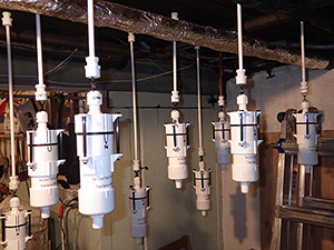
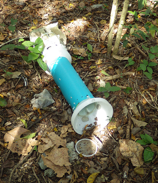
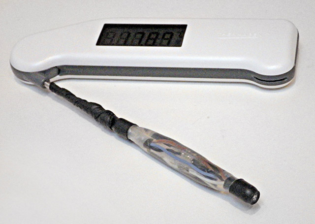
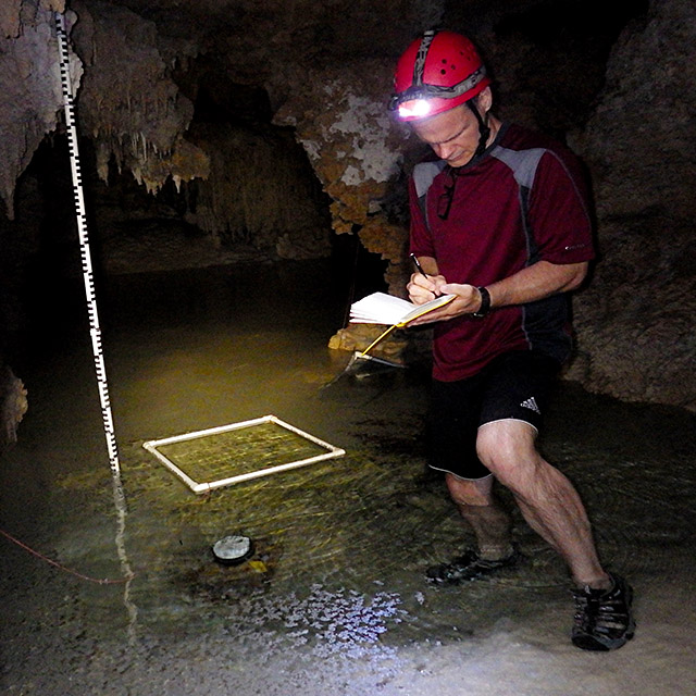
Here, I’m using the basic UNO Logger as a tethered Data AcQuisition device, recording the current used by a second data logger. Since the second logger is ‘floating’ with no connection to the UNO’s ground line, the voltage drop across the 5Ω shunt resistor is recorded using a differential channel on the ADS1115. Differential readings are also useful for sensor applications that use a wheatstone bridge arrangement.

I recently picked up a ADS1115 breakout board, and it was fairly easy to use that with the serial data plotting capability of the Arduino IDE. It’s not often that something works this well on the first try, and I thought I would post about using  the combination as a kind of  ‘poor mans oscilloscope’.   The plotter’s vertical axis auto adjusts as the value of your output increases or decreases, while the X axis is fixed at 500 points, with each tick of the axis equal to an executed serial println command.  Having the ability to spool data to the screen with a simple print statement, turns the exercise into a “What happens if I do this?” kind of process, which is perfect for providing feedback to students learning how to program Arduinos.  I posted the code used to generate these graphs on GitHub, but you will have to noodle around with it to figure out what the threshold settings should be for your particular application.

Although I already have a good method to estimate the overall power consumption of my loggers, I was motivated by this Jeelabs post to see if there was a way I could look at individual events. Even if you have a nice Rigol to play with, it can still be tricky to get all the settings and timings right because the loggers can draw anything from 0.15mA while sleeping, all the way to up to 100mA during SD writing events.  Jeelabs elegant solution to this ranging problem uses two shunt resistors and a diode, but with 15bits of differential range on the 1115, the 8x gain setting can do the job with a single resistor. (…provided I don’t exceed the ±0.5 volt limit that PGA setting imposes…) 

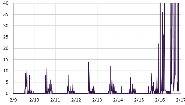
After installing Rowbergs I2Cdev library, and running a couple of jumpers, my drip sensors were generating raw count output like this:

Cave Pearl data loggers

Of course that was scrolling by like crazy, and the re-scale feature meant that the y-axis was jumping round like a bullfrog on a hotplate. You can bring the vertical axis under control by adding a few delimiter separated constants before the final data println:

Serial.print(4000); Serial.print(” “);     // sets a stable upper value line
Serial.print(0); Serial.print(” “);             //this constant sets a stable lower value

But to prevent the x axis from scrolling forever, I had to setup a trigger threshold, that would only capture a new set of readings when an actual event was occurring:


void loop(void)
{
int sensorOneCounts=adc0.getConversion();  //note we already set the mux to differential in setup
if(sensorOneCounts >= LoopThreshold) {      //rapid sampling loop to capture the event
start=millis();
for (int Cycle = 0; Cycle < ADCcycles; Cycle++) {
currentADCreadings[Cycle]=adc0.getConversion();
}
elapsed=millis()-start;// elapsed gives you the timebase for your samples
}
//A separate loop to output of the samples to the text monitor or serial plotter
for (int Cycle = 0; Cycle < ADCcycles; Cycle++) {
Serial.println(currentADCreadings[Cycle]);
}
#ifdef ECHO_TO_SERIAL    //TEXT only output of the time it took for your data acquisition loop
Serial.print(F(“Time for “));Serial.print(ADCcycles);Serial.print(F(” readings: “));Serial.print(elapsed);Serial.println(F(” milliseconds”));
#endif

}

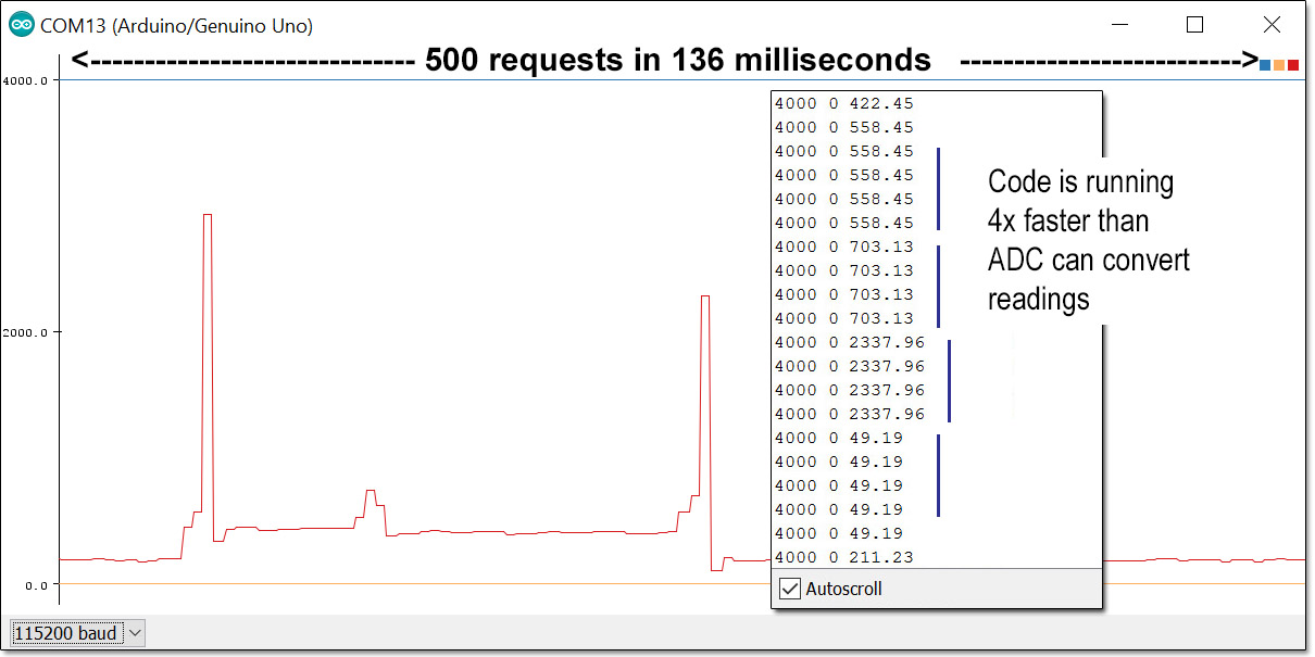
A few runs with text-only output showed the sleeping logger generating around 65 raw counts on the ADC, so I set the LoopThreshold to 75, and the plotter started behaving like an oscilloscope’s triggered sweep: scrolling 500 new readings across the screen each time the drip sensor woke up.  With a known shunt resistance, and the millivolt resolution per bit from the datasheet, I could convert the raw ADC counts to μA in the printing loop. Just for fun I also tried speeding up the I2C bus to see the temporal resolution of that sample loop at 400Khz:

Running ADS1115 with UNO as DAQ - with I2C bus running at 400HZ, the system outraces the ADCSo I was asking for data faster than the 1115’s top speed of 860sps could deliver it.  A few more trials showed that even with the Arduino’s default 100Khz bus, I had to add delayMicroseconds(400);  into the capture loop to keep the UNO from outpacing the ADC module.  I expect that will be different for Arduinos with different clocks like the promini, so one would have to make manual adjustments based on the elapsed times for each system.

These drip logger events are the result of straightforward code that follows the steps:

1) Wake from interrupt & clear the registers, update count variable
2) Turn indicator LED on & sleep for 15ms
3) Wake, turn LED off & sleep for another 32ms (to let impact vibrations die down)
4) Set accelerometer registers & go into deep sleep: wait for next accelerometer interrupt

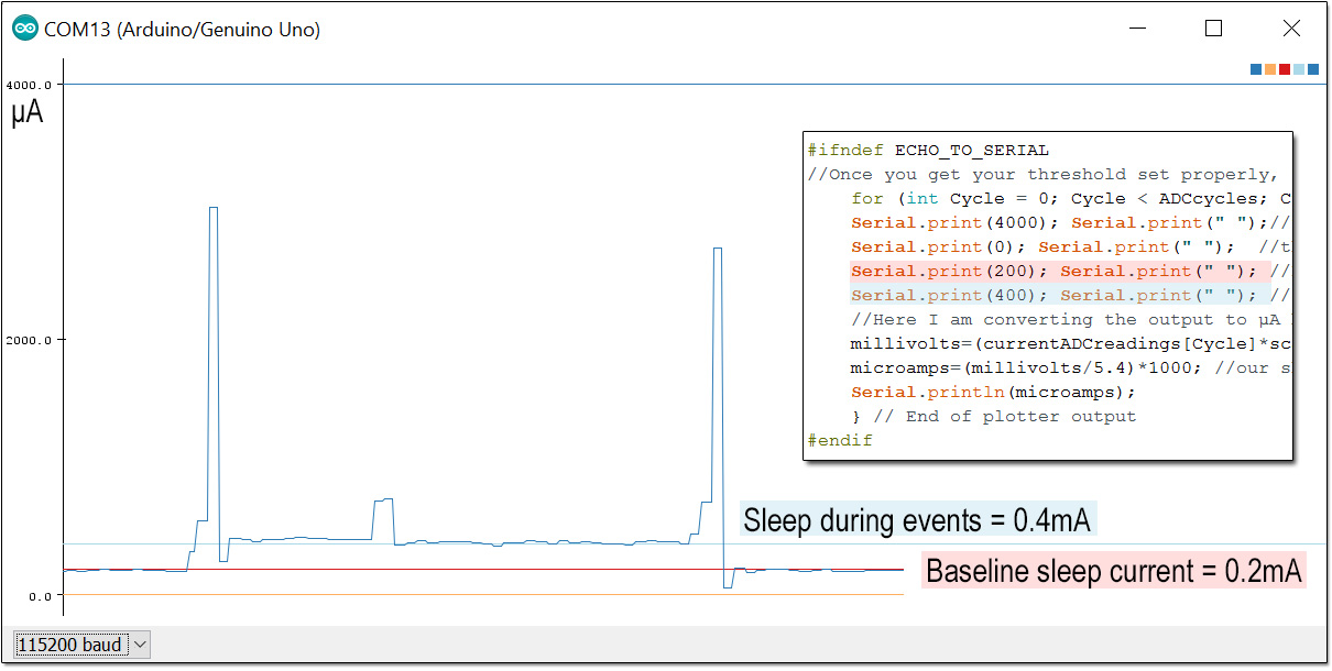
Since you can drop as many constants on the plotter as you want, it’s easy to determine the current level at a specific point on the plot by intersecting it with a new line:

Cave Pearl data loggers

Though there were no surprises in the pattern per se, it was handy to find out that the “in-event” sleep current was about twice the normal standby state. (which I confirmed at 0.2mA using a DMM)  Now I can go digging through the code to figure out what’s drawing  that extra power.

After resetting I2C bus, I tweaked the delays to exactly match the 860 sps output from the ADC. Then I sat back and waited for one of the real time clock alarms to fire:

Cave Pearl data loggers

This was my first view of that complex logger event, with variable juggling, time stamp creation, eeprom buffering, counter resets, etc. With I2C devices being able to stretch the clock whenever they need to, I had no idea how long these kind of events actually took, and I certainly never managed to capture one so easily on the old clunker scopes I could get my hands on.  The comb pattern you see there is a result of sleeping the processor for 15ms after sending data to I2C device registers; instead of using a 6ms delay while the Arduino waits for the devices to respond.  This lengthens the overall duration of the event, but the time spent running at full power is reduced.

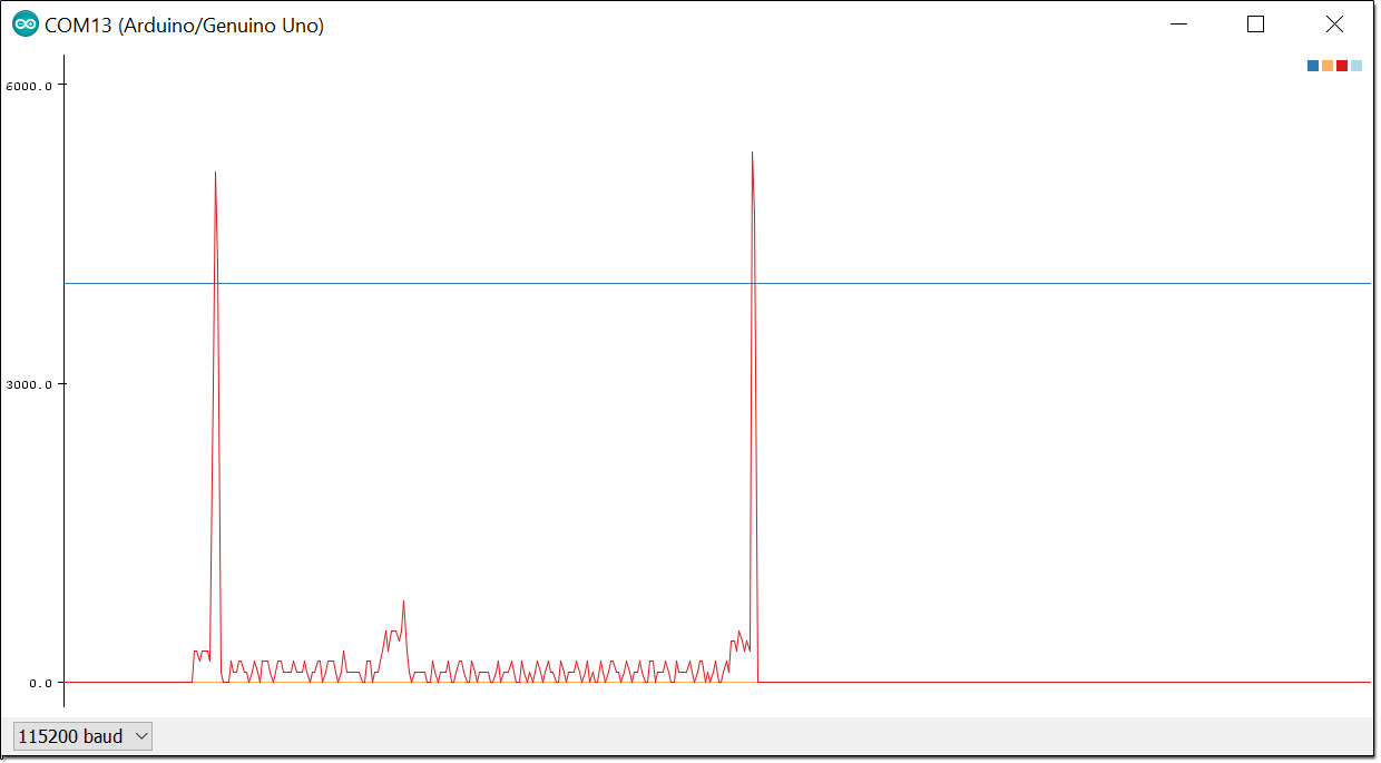
By how much? I reset the logger to use delays after I2C writes rather than sleeps and re-captured the event:

Cave Pearl data loggers

The horizontal axis is at the same scale as before. The start of the event now looks like a solid block and the overall event is about 50ms shorter.  For comparison, I’ve inset the previous graph with the sleep gaps cut out and the spikes moved together, and the two white rectangles at the top represent area equivalent to sleep gaps that were removed.  The grey area shows the power saved by using 15ms sleeps instead of 6ms delays.  To do this properly I would need to take another reading of the 3xAA power supply voltage and calculate the total power used (minus the loss on the shunt resistor), but you can see at least 25% improvement simply by comparing the plots. That kind of feedback is very helpful when you are trying to optimize your code.

Now, I can already hear people scoff that even $3 is too much to pay for a scope that won’t reach 1Khz. Indeed, with a minimum temporal resolution of just over a millisecond, the ADC frequently misses brief current peaks. I know my 8mhz promini based loggers usually draw more than 4mA while running, and you see the longer operations in the RTC/delays event pushing up towards 6 mA.

Cave Pearl data loggers

But even with the upper third lopped off those spikes by timing errors, I can still use this method to make a reasonable estimate of the power being consumed by logger events provided they don’t last more than 580 milliseconds. ( The serial plotter provides a window for only 500 samples and the UNO barely has enough variable memory for a 16bit integer array that size.) If you add the SD card library to your script you are only left with enough memory for about 100 of these samples in your capture loop, although you could try reducing the ADC readings down to 0-256 with a well tuned map function. Then you could use an uint8_t integer array, and store twice as many readings in the limited variable memory of the Arduino.  If you were just doing a classroom demo, that range would probably still give you a decent display on the plotter.

Despite these limitations, the setup is so simple that I think the serial plotter tool will become a go-to for quick looks at sensor data, perhaps even replacing some processing based demos.  The ability to connect four of these ADC modules to a single Arduino makes the platform look quite respectable as a classroom level data acquisition system, especially for environmental data that rarely requires high frequency sampling.  

If you switch to a beefier 1280 based Arduino like the Mega, or the Moteino, those memory limitations disappear and recording much longer events would become possible.  With the delays I had to put in, my gut feeling is that you could juggle a couple of these boards at a time; interleaving the readings to double or triple the effective sampling frequency. (at least until the input impedances start to mess with the shunt resistor…)  And finally, I think adding a couple of well chosen diodes to clamp the input voltage to the ±limits imposed by your PGA setting would be a good idea in the classroom, or you might loose a few of those ADS1115 modules.

It is worth noting that there is a comparator function in the ADS1115 that can be programmed to send a pin change alert when a given threshold is crossed. If I can figure out how to get ADS1115’s built in comparator working with the differential modes, this would even let me put the DAQ to sleep between sampling runs. The ADC module also has a ‘data ready’ alarm that can be enabled to tell you exactly when it has the next reading available.  I did not go that route as the generic approach used here is applicable to sensors without these features, including the ADC built into the Arduino. 

There are plenty of other serial data plotting programs, but using the free IDE version like this is an iterative exercise, forcing you to switch between the serial text monitor & the serial plotter a few times to tweak the delays and constants. If you are using an UNO in a classroom setting, this in itself is a useful activity.  And given how cheap basic DAQ modules are these days, choosing to use an Arduino is always about the showing the process rather than just getting a final result.

Addendum 2016-08-15:     A MUCH faster DAQ with the native UNO ADC

 Here I’m reading the voltage across a 10Ω resistor with the UNO’s built in ADC. To do that I need to join the ground lines because the Arduino can only take single-ended readings. That also forces me to put the shunt on the low side line so I don’t exceed the 1.1 vref. This arrangement causes the drip sensors’s effective ground line to jump around as the current through the resistor changes.


Here I’m reading the voltage across a 10Ω resistor with the UNO’s built in ADC. To do that I need to join the ground lines because the Arduino can only take single-ended readings. That also forces me to put the shunt resistor on the low side line so I don’t exceed the 1.1 vref. This arrangement causes the promini logger’s effective ground line to jump around as the current through the resistor changes.

The folks over at Measuring Stuff  posted a page called The Arduino DAQ Chronicles, which goes into some detail on the process.  It’s a good chunk of background reading even if you are using the ADS1115 ADC described above. The Arduino’s native ADC delivers 10-bit readings, (ie 0-1023) and compared to the relatively pokey ADS1115, a typical UNO can take several thousand analog readings per second; outperforming the ADS1115 by a fair margin. The challenge is balancing the reduced resolution with the other limits imposed by the method itself. Even if you increase the sensitivity of the native 10-bit ADC by changing to the internal 1.1vref, you only reach 1.1v/1024 steps = 1.07 millivolt per bit. Remember that my loggers are sleeping at 0.2 milliamp x 5Ω shunt resistor = 1 millivolt so we are operating right on the lower limit of the ADC resolution. With that 1.1v cap on the ADC input, and a potential 100mA peak current (during SD card data saves), the largest shunt resistor I can use is 1.1v/0.1a= 11Ω. So to get the Arduino to discriminate the low currents we need to use a pretty  large shunt resistor value, and allowing the voltage drop to get that high imposes another challenge in that the drip logger would only be left with 4.5v (the 3xAA battery) 1.1v drop on shunt = 3.4v. That’s right at the minimum input voltage needed by the 3.3v regulator on the Arduino promini board, risking a potential brown-out in the middle of the SD card writing process.

But hey, lets pop in some new batteries, and see what we get:

FirstRaw

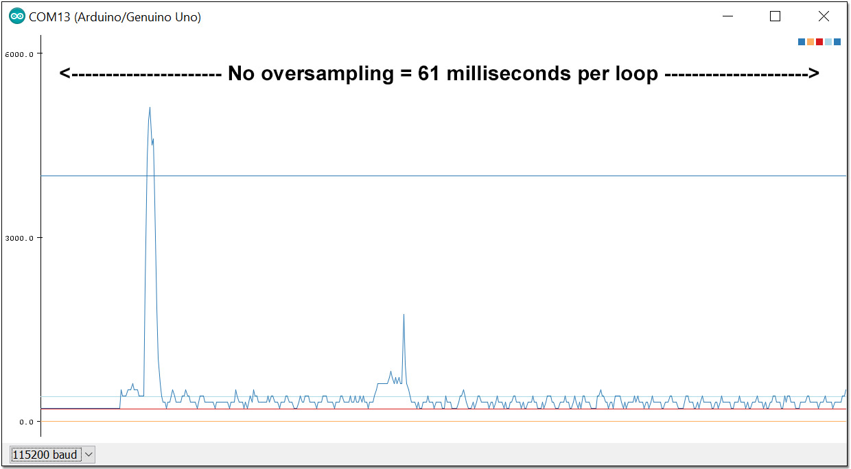
Not too bad, but that’s a noisy plot with lots of jitter on the base line. Having 1-2 bits toggle like that is typical for ADC’s so there is probably nothing I can do to get rid of it. And the drip sensors resting state reads at zero when it should be registering at least two counts. It is also common for an ADC to under or over read by a few bits, so I added an offset adjustment into the code to bring that sleeping baseline up to the 0.2mA that I have already confirmed with a multimeter.

Then I realized I still had the 400us delay in there from the ADS1115, so I took that out:

Cave Pearl data loggers

Crikey! Even with the code overhead, that thing is taking over 8000 samples a second! That’s far too many readings for the serial plotter to handle if I want to view long events.  And that first spike goes upt to about 5mA – exactly where it should have been on the ADS1115 readings if that module had not missed them at 860sps.  So how do I maintain the Arduino’s ability to spot those rapid sample peaks, but only send 500 readings to the screen?

Instead of delays, I decided to create an “oversampling loop” that creates a running average using a low pass filter, but also checks for peaks throughout the process. You can dig into the code for this over at GitHub, but the basic idea that is if a peak occurs, then the highest reading in an interval becomes the final reading. If a decreasing trend is found, then the output from a leaky integrator becomes the final reading for that interval. So the readings get smoothed on the way down, but not on the way up.

Here is a try with the oversampling interval set to six ADC readings:

BothEvents6xoversampling

That’s the RTC event (with delays) and the drip triggered event at the same scale.

Now here’s another run with a 15:1 ratio:

OS15-900msPerloop

Squashing more than 7000 raw readings into a 500 line display really starts to distort the curve, but everything is still recognizable, and more importantly, the peaks did not get chopped off like they did with the ADS1115.  Woot!

Now we have a method that lets us adjust the serial plotter’s display to match the event we are trying to see, provided we don’t over-interpret the accuracy of those heavily averaged interval numbers. And rapid sampling can introduce other issues to deal with. For example: Dustyn Roberts has a useful post on creating very precise time stamps with the micros(); function when you are sampling faster than 1 millisecond. 

So within limits, a standard Arduino gives you good temporal resolution but can not detect less than 1 millivolt of change, while the ADS1115 gives you precision down to an impressive 0.0078 millivolts (@16x gain) but is not so great for tracking really brief events.  If you need both resolution & speed, you need opamp circuits designed for the specific situation, as in the Jeelabs example. It’s also worth mentioning that the Arduino ADC also supports a comparator that you could use for the threshold function more elegantly than I’ve done here.  And with such a low impedance input, you can also double or triple the sampling rate by changing the ADC clock prescalers (this is also in the code on GitHub) Both of those things are described in detail over at Nick Gammons excellent page on ADC conversion on the Arduino.

Addendum 2016-08-16

Hopefully they will add export options (like other serial tools) to the plotter in the future, but for now you can manually copy data out of the serial text monitor and paste it into Excel.  Before you start a long run for export to a spreadsheet, comment out the constants that you were printing to stabilize the plotters y – axis, so that only the numbers you are interested in are sent to the serial output.  If you are waiting for an event to happen, it often helps to add a threshold test so that the serial monitor is not just filling up with uninteresting data that you would have to prune away later anyway:thresholdprintline

Then after your DAQ has been capturing events for a while, click inside the serial monitor window,  select all the data & copy it (on a windows machine that would be [CTRL]+[A] followed by [CTRL]+[C] ) then open a new spreadsheet and simply paste the data into an empty column.

This lets you compare the events side by side:

CopySerialdataintoExcelIf you want to graph more than one number, then add a comma between them with Serial.print(“,”);  remembering to use println on the last variable being sent.  Then you need to add the intermediate steps of pasting the data into a text editor like notepad, and saving that text file. Then change the ending from .txt to .csv and Excel will open it directly. If you can’t change the filename, you can still import the text file and specify comma delimiters:

TextImportExcel

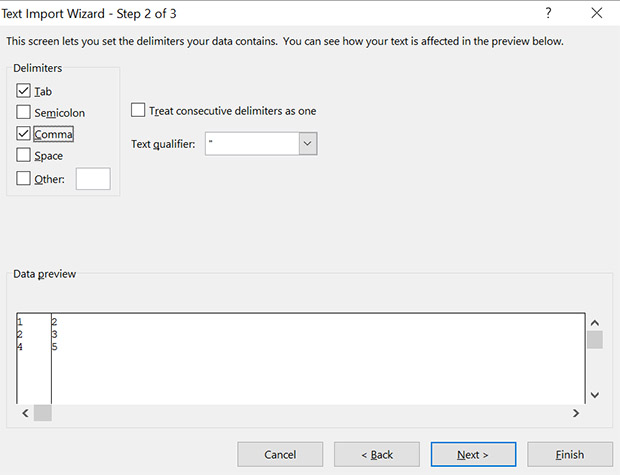
to put the numbers into adjacent columns. If you don’t have excel, there are plenty of other data plotting options out there. And programs like coolterm, can save you from having to do those cutting & pasting steps.

Addendum 2016-10-13

Gokul Shrinivas just posted a neat little bit of code at hackster.io that reads the Arduino ADC at a cracking 68k samples per second out of a Arduino Due by directly accessing the ADC ports as soon as the DataReady interrupt is triggered. 

He starts with defines:

#define ADC_MR * (volatile unsigned int *) (0x400C0004) /*adc mode word*/
#define ADC_CR * (volatile unsigned int *) (0x400C0000) /*write a 2 to start convertion*/
#define ADC_ISR * (volatile unsigned int *) (0x400C0030) /*status reg -- bit 24 is data ready*/
#define ADC_ISR_DRDY 0x01000000
#define ADC_START 2
#define ADC_LCDR * (volatile unsigned int *) (0x400C0020) /*last converted low 12 bits*/
#define ADC_DATA 0x00000FFF 

And the sampling loop becomes

ADC_CR = ADC_START ;
  for (i=0; i<320; i++){
    // Wait for end of conversion
    while (!(ADC_ISR & ADC_ISR_DRDY));
    // Read the value
    analog_data[i] = ADC_LCDR & ADC_DATA ;
    // start next
    ADC_CR = ADC_START ;
  }

He used an LCD screen for the scope, but I am wondering if it would be possible to refine my oversampling trick to squeeze that many data points on the serial plotter somehow…

And I wonder if this trick is even available on the 328p? I guess I will have to go looking at other Arduino Oscilloscope projects. The problem is that most of them seem to be using 8-bit signals from “free-running” modes, and I rarely have an application that needs less resolution. Here’s a project doing Interrupt-Driven Analog Conversion  with an ATMega328p, and Nick Gammon mentions it here, but no one does a speed comparison with the ten analog 10-bit readings you get per millisecond using plain old analogRead();

Even if there is no speed gain, perhaps I could do calculations while I was letting the ADC read continuously to speed up the overall sampling loop.  I could see myself getting out of sync pretty easily though, unless I deactivate the general interrupt flag and activate it again (with  cli() and sei()) or I would randomly miss readings.

Nick posted a code example of reading the Analog-to-Digital converter asynchronously that seems to solve the synchrony problem.  He’s also posted an interesting ‘sleep during ADC conversion’ example buried in there, but that’s only useful if you are not using timers & PWM at the same time, and I often do that…

Update: the Hackster.io project listing magically evaporated… and I just found exactly the same code at Bruce Land’s Hackaday project from 6 months ago. So I think proper attribution for the script above should go to Bruce.

Addendum 2017-01-10

I’ve been playing around with the ADC clock prescalars, and with the asynchronous reading code available over at Nick Gammon’s site to try to get better temporal performance out of my little UNO-scope.  With such a low value shunt resistor the ADC seems to read fine even if you crank it up to about 40k samples/second. Unfortunately you pass a point of diminishing returns due to the processing overhead with the interrupt based asynchronous readings,  so async reading actually reduces the number of readings per millisecond at the higher clock speeds. If you want to play with this approach yourself, I’ve posted the update with the prescalar settings to GitHub.

Addendum 2017-02-27

Anyone interested in using an Arduino as at data acquisition device will probably want to see my recent post: Enhancing ADC resolution with Dithering & Oversampling
For an unmodified UNO,  Qwerty’s triangular dither method is probably the easiest one to use, but for 3.3v boards I’d go for the Toggled pin dither method I outline at the bottom of the post.

Addendum 2019-09-27

Microsoft has added a ‘data streaming’ plugin that’s free for Office 365 users which will accept data directly from an Arduino. If you are a student, the 365 software itself is also free. But for those of us running older versions of Office, the cut and paste method described above still works fine.

Build your own Arduino Starter Kit for the Classroom

A typical student starter kit.

It’s August, and we’re assembling kits for another run of the instrumentation course.  Over time we have come to rely on 328p based microcontroller boards (aka: Arduinos) so I though I would post a list of the parts & materials we use to help others fire up their own classroom. More than a few people have requested this since I posted the UNO based logger tutorial.

This information should also be looking to buy an all in one solution for their first citizen science project.  Don’t reinvent the wheel if you don’t have to: there are lots of premade Arduino kits out there.  However we found that many had parts we simply didn’t need, as we wanted a minimal ‘starter kits’ designed to exactly match the lessons in a course focused on environmental monitoring.  We also hand out extra parts for some tutorials as needed through the course, and the students receive a second project box when they start building their stand-alone  projects. Cave Pearl data loggers Even if you want that level customization, it might worth looking at some basic electronic component kits, and building your classroom set on top of those. The DIY approach will save money, but you pay for it with time.  Most of the eBay parts shown here took about two weeks to ship, with some stragglers taking almost a month to arrive.

You will need more than an Arduino and a few components  to set up a classroom, so I am including tools & other miscellaneous bits of hardware that we use in the lab. I would not describe any of these as high quality equipment, but they are ‘good enough’ to get things rolling on a modest budget.  Even if you go with cheapest possible suppliers – you are doing great if you can run a fully developed course for $150 a seat. If you purchase a soldering station for every single student, and use UNO’s + a typical Pro Mini logger build, you’re looking at about twice that much for the initial run of your course.


Components for the UNO based Datalogger:

TransparentSinglePixl
UNO Data logger Kit: $25-50 / seat
UNO_100pxw Arduino UNO R3
The real thing, and tough as nails. All of my old UNO R1 boards are still operational despite years of abuse. If you can’t afford the real thing due to budget limitations, then at least donate a few bucks to help them keep the Arduino open source project going.
$24.95
UnoClone_100pxw UNO clone (incl. USB cable)
If your budget forces you to go this route, choose clone boards with ATmega16U2 or 8U2 UARTs (like those in the genuine UNOs) to avoid problems with the IDE. If you can deal with the driver issues, there are clones for as little $3 with alternate UART chips like the CH340 – but CH340 UARTS  do not work with Macs.
$7.20
PlatformBase_100pxw
Transparent Experimental Platform Base-plate
Last year we made our own base plates with M3 risers and Plastruct Styrene sheets. But these acrylic boards save a lot of time. Check left/right side orientation of the holes on the board before buying and the ones with the larger threaded nylon standoffs tend to be better options.
$1.50
MiniBreadboard_100pxw Mini Solderless Breadboard 400 Tie-points
Get at least two per student, in case they need to expand their projects. The plastic in these cheap breadboards tend to “warp” slightly over time and the adhesive layer on the back is not thick enough to accommodate this bending so they will slowly come away from the mounting surface. If you are attaching your breadboards to acrylic plates beside an UNO – add an extra layer of double sided foam tape to the bottom of the breadboards before sticking them down.
$1.20
40p10cmdupont 40wire Dupont 10cm Jumper cable
An alternative to loose jumpers wires, and they make the student kits look much nicer at the beginning of the term. Have students make longer or shorter jumper wires by hand when they need them to provide practice with the crimping tool. Jumpers you make yourself are always more reliable!
$1.00
JumperWire22AWG_100pxw 22AWG Solid Hook up Wire Kit
One box will cover the entire class and they should know how to cut and strip wires properly. Don’t bother with pre-cut solid core jumper wire sets as the set lengths are almost never the right size. Striveday also sells mixed boxes of solid core wire.
$20.00/box
SDmodule Micro SD Card Memory Shield Module
This shield is ONLY for UNO based loggers (not the ProMinis) Don’t forget to buy μSD cards to go with them. Test any used ones to make sure they are ok.
$1.00
RTC_100pxw DS3231 & AT24C32 IIC RTC Clock Module
I have a page describing these RTC board in some detail here. You will also need a CR2032 3v Lithium coin cell backup battery, after you remove the charging circuit resistor. The DS3231-S and -N chips are MUCH better than the DS3231M variant.
$1.00
Keyes3ColorRGBLED_100pxw 3-Colour Rgb Smd Led Module (with built-in limit resistors)
There is nothing special about this common cathode 5050 LED module, but it’s easy to remove & re-insert without bending the pins, and the low profile helps it fit in the kit boxes. The 200k limit resistors that come built-in on the green pre-mounted boards give you a current that approaches Arduino pin limits, so it wouldn’t hurt to add another 500-1k ohm on the GND line with these modules for extra safety.
$0.80
Tweezers_100pxw Vetus ESD-15 bent tip tweezers
Look for the better quality ones with the rounded ends that come to a sharp point. 
$1.00
ICbox_100pxw 10 Compartment Small Part Storage Case
To keep all the led’s, resistors, etc. from rolling around loose inside the larger clip boxes. Get ones where the section walls can be removed to make room for longer parts. There’s a range of other cheap fishing tackle and (non-waterproof) compartment boxes available.
$0.70
SteriliteBox Sterilite 1961 – Small Clip Box for Lab kits
Expensive, but they survive in a student back pack. You can find $1 clip box alternatives (like the photos at the top of this post)  at your local dollar store.  Various  other clip lock food / snack containers can also be used, and some can even be pressed into service as project housings.
$4.25
Outdoor Products Watertight Box
Measures 3.5 x 6.8 x 8 inches with 1.5-liter capacity so this one is for projects that need a lot of internal space –  it could also be pressed into service as a housing for larger UNO based projects going outdoors ( ie: lots of room for big batteries! ) Also see:  the $6.00 Husky 6″parts bin, 7×5.25×3.5″ Parts Organizer , and 4x4x2 in. Grey Sch.40 PVC junction boxes are another housing option, which are also available with 4 & 6 in. depths.  
$6.99
Plano 3440-10 Waterproof Stowaway (3400 Series)
Makes a reasonable “instant” waterproof housing for smaller projects and indicator LED’s can still shine right through: We use these on the Pro Mini based logger build. The actual usable “interior space” of the box is 8.1cm x 15.5cm x 3.5mm, which is just a a bit too small for the 83mm x120mm acrylic platform bases used for the UNOs (you can press them in, but they are very tight – better to cut them down a bit)   Pelican 1020 Micro Cases accomodate that UNO platform easily though they are the luxury polycarbonate option which cost more than 2x as much as the plano box. Polyc does allow you to put display screens and solar cells inside the housing because it passes all of the visible spectrum with little loss. Of course that also means that whatever’s inside the case will really cook (60-90°C) if you leave those housings exposed to full sun.
If your build is “skinny” enough, 2″ PVC compression couplings can be used as a housings with pvc plugs at each end. All these ideas require you to add cable glands and wire pass-through connections.
$4.96
CheapMultimeter_100pxw Basic Digitial Multimeter DT-830D
We have better meters in the lab (like the EX330 which is pretty good for ~$50) but at $3.00 each you don’t have to worry about students loosing or breaking them. Have replacement 9v batteries on hand, as people frequently forget to turn them off. Expect 1-2% error on all readings and don’t try to measure large resistors in the Meg ohm range (because the meter itself interferes with that reading) . Expect 20% of your order to arrive broken during shipment from China.
$3.40
UT120C Super Slim Pocket Digital Multimeters
Often you need a “shirt-pocket” sized multimeter during fieldwork, and we usually have a couple of these along for the ride. Cheap enough to be expendable, but functional enough for most jobs on site, but again not as accurate as the EX330. 
$15.00
eyeloupe Folding Magnifier (5x)
Useful for inspecting solder connections but not good for soldering because you inevitably need both hands to do the work. For the soldering stations we pick up cheap reading glasses from the local dollar store.
$0.55 ea.
Note: The stuff above this line goes into every UNO logger kit, but I am adding a few optional things to this list that might be appropriate for other courses:
MinimalKit_100pxw Minimal electronic components kit
Even though we don’t use them, I wanted to put this in here as an example of a minimum component package that could be a starting point for your custom kits.
$3.50
ElecfansKit Slightly less minimal component kit
Another one that’s almost tempting. Search eBay for ‘Electronics starter kit for Arduino’ and you find oodles of these. If you are only making a small number of kits these might be the way to go. But if you are making six or more, check the basic components list below, as most of the parts in these packages are pennies each if you buy them separately.
$7.70
6xAAbattery_100pxw 6xAA Battery Holder Box for Arduino
These will power an UNO for about 40 hours of continuous stand alone operation. You can stretch that out with processor sleeping & other tricks.
$2.45
PWradapters_100pxw 9 VDC 1000mA regulated power adapter
5.5mm/2.1mm barrel jack, positive tip. Expect these cheap ones to be noisy as heck compared to the ones from Adafruit. We run most of the UNO based lessons tethered to a USB cable, so these rarely get used.
$2.27
LongBreadboard_100pxw MB-102 Solderless Breadboard 830 Tie Points
They don’t go into the student kits, it’s a good idea to have a few of these longer breadboards around.
$2.00
TranspShield_100pxw Arduino UNO R3 Transparent Case
An alternative to the flat platform approach we use  would be to try these in combination with a breadboard shield
$1.60
BreadboardShield_100pxw Mini Breadboard Prototype Shield
With a little creativity you could squeeze low profile components for the data logger onto this if you find an SD card adapter, and an RTC with perpendicular pins.
$1.80

Basic Electronic Components:

Most electronic components can be had for pennies if you buy them in quantity. And the difference between low end parts and name brand stuff can be more than an order of magnitude.  That doesn’t mean that off the shelf kits are a bad thing, it just means that what you are really paying for is someone’s time selecting and packaging it.  That still might be the better option for you if you can afford it.

TransparentSinglePixl
Basic Components:
StanleyBins Stanley Removable 10 Compartment Organizer
Before you buy a bunch of tiny little parts, you need some way to organize them. I usually put the items into 3″x 5″ or 4″x 6″ bags, which then go into these compartments.  Pink 4Mil Anti-static Poly Bags come in all sizes, and work well for this. Being able to remove the section boxes from these organizers to lay out specific parts for a tutorial also comes in handy.  See: Organizer Bin Storage Unit See: Stacking organizers See: Tool Storage
$17.00
StanleyShallowOrg Stanley Shallow Organizer, 25 Compartment
This organizer is better for really small components & IC’s that you only have a few of, but you still need to bag them or they get jumbled.
$12.00
ELENCO WK-106 Solid Hook-Up Wire Kit 22 AWG
22 AWG works reasonably well with breadboards, get at least 6 colors/150 feet. Remember to specify how much to cut from the spool in your lab instructions, or your students will pull 2 feet of wire from the box when they only need a couple of inches on the breadboard. Get two boxes at the start of term.
$19.00
AdafruitWire_100pxw 26AWG Silicone Cover Stranded-Core Wire – 2m
This high strand count wire from Adafruit is the nicest stuff you are ever going to work with, and is my favorite after trying just about everything else on the market. Simply fold & cut those pre-cut 2m lengths four times and you end up with 12cm lengths which are perfect for including in kits. [Colors:Red,Black,White,Yellow,Green,Blue,Grey,Orange]
$0.50/m
CheapWire_100pxw 60m/box 26 AWG 10m x 6 colors Cbazy / Striveday Silicone Jacket Wire
As your projects get more advanced you can never have enough different colors of wire. And there are other box sets to add Orange, Brown & Purple . The thing to watch out for with wire sourced from eBay wire is that some vendors sell crappy seven-strand wire,  which will not stand up to frequent bending like the highly stranded Adafruit 26awg. I also keep some thinner 28AWG and 30AWG wire with high strand count around for finer soldering jobs (eg  here)
$17.00/box
CBAZY Stranded Hook up Wire 26-30 AWG Flexible Silicone Wire (108 Feet)
You can never have enough of certain colors, so I always order extra 30m rolls of RED & BLACK wire for battery connections.  [Colors:Red, Black, Blue, Brown, Green, Grey, Orange, Purple, White, Yellow]  16-30awg available. ~$0.33/m
$12/30m
Hshrinkspool_100pxw 1/16″ 2:1 Clear Heat Shrink (MIL-I-23053/2, class 2)
Unlike normal heat shrink, mil-spec is very thick and holds its shape after cooling; making it easier to route cables in a housing. Watch for eBay vendors that advertise mil-spec, and send you the thinner cheap stuff.   I think of 1/16″(=1.5mm) heat shrink as “1-wire sized”, 2mm = “2-wire size” and 1/8″(=3mm) as “3-wire size” when working with 26awg. Always buy clear heat-shrink tubing for the classroom – so that you can see when poor soldering has caused a problem with the circuits.
$12.00/100ft
I add male DuPont crimps & a bit of heat shrink to thin lead components to make the breadboard friendly

Resistors: Lead diameter makes a resistor breadboard friendly or not. You generally want 0.6 mm not 0.4mm leads, though it is inevitable that you will end up buying a few cheap multipacks with the thin leads. ( Note: You can add male DuPont crimp ends & a bit of heat shrink to components with thin leads to make them breadboard friendly : see inset photo) Brand-names like Vishay, Xicon, KOA Speer are usually very good, but you pay 2-10 cents each for them, and the Vishay leads are sometimes thick enough that you need to cut them at an angle just to insert them in the breadboard.  (Often you can find new-old stock bag lots of Xicon carbon resistors on eBay reasonably cheap)  The cheap old carbon resistors often tend to have thicker steel leads while the better brands have softer copper leads which bend more easily. I find 1/4 watt to be the most practical size and 1/2W metfilms are physically about the same size as 1/4W carbons. Beige-background carbon resistors seem to be much easier to read than blue-background metals, but if you need 1% tolerances, you won’t have much choice. 1/8watt metfilms are very tiny, which can be helpful if you need to put a resistor into a small place, like between two pins on a breakout board. Wherever possible, buy 1% tolerance (or better) resistors, rather than 5%, as this affects your sensor accuracy when you use them in voltage dividers – which is a common way to read sensors.

MetfilmResisorSet1 130 values 1-10MΩ 1/4W Metal Film Resistors Assortment
Crappy thin leads, but a huge range of values to have on hand at the beginning of a class – in fact I would order two of these to get started.   Then order 50-200 of the individual resistor values as needed for your labs/exercises. Be prepared for it to take 2-4 weeks for resistors to show up if you order them via eBay.
$10/2600pc
IndMetfilms MetFilm Resistor 1/4W 0.25W ±1% [Various Sizes]
100 pc of specific sizes with thin leads. We usually put five to ten of 330Ω, 1K, 4.7K & 10K in each kit, but you can tune this to your curriculum and/or hand out other specific sizes at the beginning of each lab.  After you get better at soldering, you will probably switch over to 1/8 watt resistors, as their smaller size lets you put them into tight spaces: like between the pins on a promini board. Also note that metal film resistors use a 5-band code to indicate their value, rather than the 4-band you see on carbon resistors. But we teach students to always check resistance values with a DVM to catch manufacturing errors, and because it’s quite common for them to cook their resistors, or bend the wires too much & break the connection,  when they are just learning to solder.
$1.89/100pc
HalfwattCarbons 1/2W Carbon Film Assortment (30value x10pc 1-3MΩ)
Sometimes the 1/2 watt size is easier for beginners to handle. It also helps to have “exercise specific” resistor values look physically different from the other resistors in the kits. These still have thin leads though.
$3.80/300pc
carbons Carbon Resistor 1/4W 0.25W 5% [Various Sizes]
Just a typical eBay search link to give you an idea what’s available. Usually these carbons have nicer thicker leads but the quality varies. Check for free shipping.
$1.00/100pc
Components: Most hobby market parts distributors have “Assortment Kits” for commonly used components and its a good idea to just buy a selection those when you are starting out. It might be a while before you actually dig into that mixed bag of capacitors for the odd value you need for that circuit you just found on the internet, but when it happens you will be glad you spend that $1 six months ago.

Where to buy them: I’m going to list several kits from Electrodragon as examples, but there is nothing special about them and you can often find a very similar sets on eBay for significantly less. A common problem with all the overseas suppliers is that it usually takes 3-4 weeks for stuff to arrive, and that can stretch to 8 weeks. So if you realize that you need something quickly, go to Sparkfun/Adafruit/Pololu/Amazon etc and just pay the $15 delivery charge. The thing that makes this complicated is that now a lot of domestic websites like Amazon, Digikey etc, often just acting as distributor for these exact same components from China. Another draw back with Amazon is that those easily recognized boxes are big targets for porch thieves.

My rule of thumb with dodgy flea market sites like Banggood, Dealextreme, AliExpress, etc. is: “If this order never arrives, how unhappy would I be about that?” If the answer to that question is “Quite a bit” then you should order that part from a reputable vendor.  More than 95% of the things I order from eBay do arrive…eventually…though it’s common for things like sensor modules to be significantly different than the photos shown in the listing. Overseas suppliers are best used where fakes are unlikely (or don’t matter) like resistors, LEDs, displays, pin headers, switches, wires, vanilla transistors, battery holders and similar items. Or a one-time thing you just want to play with to see how it works. For more complex sensors and microcontrollers it’s very easy to get counterfeits or rejects that kinda seem to work initially, but are way out of spec. In those cases I’m prepared for a percentage of duds, and so far I’ve only had one out of maybe 30  purchases. The cost of returning is usually more than the item’s worth, so you have to be prepared to bear the loss. There are even some complex components I wouldn’t buy anywhere else like the ESP’s, since these are manufactured in Shanghai, so you wouldn’t find these cheaper somewhere else.

LED's 5mm LED Light Diffused Assorted (5 Kinds*20PCs)
Having the colored plastic makes it easier for students to identify which LED is which. [red, green, yellow, blue, white]
$1.80/100pc
RGBled10mm LED diffused RGB 10MM Common cathode
Having the RGB led a different physical size from the one-color LEDs makes it easier to identify them in the kit. Common cathode means you can use one limit resistor on the ground line. You can use a CR2032 coin cell to identify which leg is which color quickly by putting the common line on the negative side of the battery.
$2.65/10pc
mixedcaps Ceramic Capacitor Assortment (10 Kinds x 50 PCs)
The most important thing to know about ceramic capacitors is that they have the worst thermal coefficients of any component you are ever going to see.  So to build a circuit which will work in real-world environments you need the dielectric to be rated at X7R (±15% from -55 to 125C) or better.  Garden variety Y5V (±82% from -30 to 85C) caps also loose about 30% of their capacitance in their first year of operation (X7R’s loose <10%) and you need to compensate for that too.   And finally you need to buy caps rated for 50v, if you want to use them with 5v because the bizarre rating system means that you could loose up to 80% of the rated value as you approach the rating on the label. 
$11/500pc
cCaps 100PCs Ceramic Capacitor [30pF,10nF,100nF]
The four most common sizes of capacitors to keep on hand are 10μF (106), 1μF (105), 0.1μF (104) and 10nF (103). Get 100 of each to start, as they are frequently used for bypass/decoupling. Most of the time you will be using: 104 (100nF) but like resistors it’s handy to have small mixed assortments on hand for one-of builds. 
$0.80/100pc
EcapAssortment Electrolytic Capacitor Assorted (0.22UF-470UF, 12Kinds)
I rarely use these (unlike the little ceramics which get used all the time) Keep an eye on polarity because electrolytics (and Tantalum capacitors) will explode if you put them in backwards.
There are other kinds of capacitors out there, and for sensor circuits that have to be stable with temperature, or over long periods of time, plastic film capacitors are often a much better choice than either electrolytics or ceramics: I use Polyphenylene Sulphide (PPS +/-1.5%) or Polypropylene (CBB or PP +/-2.5%) when I can since their aging rate (expressed as % change /decade hours operation) is negligible. The only drawback is that they are relatively large, so for a given value, the film cap might be the size of a jellybean, when the equivalent ceramic cap would barely big enough to solder to without a magnifier lens.
$3.30/120pc
GeneralDiodePack General Diode Pack (8 Kinds)
(1N4148 -25PCs, 1N4007 -25PCs, 1N5819 -10PCs, 1N5399 -10PCs, FR107 -10PCs, FR207 -10PCs, 1N5408 -5PCs, 1N5822 -5PCs)
$3.00/100pc
INDdiodes 50PCs Diode [Individual types]
1N4148 is the bog-standard signal diode so it might be worth keeping some of those on hand. When losses matter @ low voltages and low currents, it’s better to use 1N5817 Shottky’s (ie: for things like isolating battery banks from each other)
$0.75/50pc
DiodePack_100pxw Common Zener Diode Pack, 0.5|1W, 3.3V-30V
(14 kinds, 5pcs each) Each Zenner has a specific breakdown voltage, so it might be a good idea to wait till you know which ones actually need and order only those specific types.
$1.70/140pc
TransistorPack General Transistor Pack (17 Kinds x 10PCS, Low Power)
Like Zenners, there are many different flavors of transistor out there, and you should figure out which one you need before buying too many of them. So perhaps just order this pack as a backup, and wait till you know which specific ones you need. For example: the 2N2222A is one common NPN BJT that most everyone seems to use, and they are about a penny each.  See: Building a Friendstrument. See: Transistor as a Switch  See:TransistorCalculator.       Rule of thumb for using cheap transistors as switches:  Size your base resistor to make the base current twice the calculated value for the smallest hFE you see listed in the data sheet (see calculator here) provided that does not exceed ~20mA digital pin current on an Arduino. Don’t forget to add pull up/downs for stability. Note: E-B-C pinouts are not standardized For most 2N2222s, when the flat side is facing you, the pins are E-B-C but some  are C-B-E.  If  you get C/E reversed the transistor will still sort of work but with a lower β (beta). This is highly annoying to debug…      To test an unknown transistor with a DVM in diode test mode, attach the red positive lead to the base of the transistor, and the black neg. lead to each of the two unknown legs in succession: The slightly lower of the two voltages will correspond to the collector-base junction, and the slightly higher reading will be the emitter-base junction.
$2.60/170pc
2N7000 2N7000 TO-92 N-Channel Mosfet (200mA max)
These mosfets are like “Transistors for Dummies” and work great as digital switches when connected to 5v Arduino digital pins – and you don’t have to do the calculations for the base currents, etc. So they are much easier for beginners to use although they will set you back a whopping four cents each. Note: A 100K resistor between the gate and ground keeps the N-fet off by default, but you can generally operate mosfets without a pin-gate resistor, though many recommend 150 ohms there. N-channel mosfets are usually placed on the ground side of the controlled circuit.


Note for 3.3v systems: The 2n7000 can be used with a 3.3v Arduino to control things like LED’s, but they only pass between 30-60mA because the controlling voltage (Vgs) needs to be at least 4.5v for the 2n7000 to be fully turned on. With only 3.3v control, the resistance across the 2n7000  is ~ 3-4 ohms, so there will also be substantial voltage drop across it.  Although “logic level” is not exactly as standard term, mosfets designed to work with 3.3v mcu’s often have an “L” in the part number, ex: IR540 (non logic level) vs. IRL540 (logic level).  Ideally you want the MAX value for Vgs(threshold) to be lower than 2.4v in the datasheet, or you want to see an RDS(On Resistance) quoted for 2.4v, or lower.  When considering the On Resistance, calculate the voltage drop that will occur when the MOSFET is On and the load is operating. If the load draws 50mA, and the RDS(on) is 3 ohms, the vdrop across the fet is 0.05*3=0.15v. The tricky thing about this calculation, is that the On resistance changes with the level of the controlling Gate Voltage, and as you get closer to the Vgs(th)threshold voltage, the on resistance increases – so you need to dig into the graphs on the datasheet to figure out what the actual vdrop is going to be. Since the whole point of using a MOSFET as a switch, is to achieve lower Vdrops than you would get using a BJT, you want the vdrop  across the FET to stay below 0.25v maximum.   Probably the closest thing to a 3.3v version of the 2n7000 would be one of the Supertex TN0702 or TN0604, which come in the same TO-92 package. They can’t switch much current, but if you are careful it is possible to control parallel mosfets for increased capacity

You can solder legs onto SMD parts to make them breadboard friendly.

Most of 3.3v N-channel mosfets come in tiny surface mount SOT-23 packages:  The Philips pmv30, pmv31 and pmv56, and the Vishay Si2302, Vishay Si2356DS  , Si2312BDS (or Si2333DS /DDS for P-channel)  The Fairchild NDS331 / 335 is another good option with very low on resistance and a gate threshold of only 1v.  The problem is that none of them are available in breadboard friendly TO-92 packages  so  you might have to mount them on SOT-23 adapter boards to use them, and if you willing to do that it might be worth going to the Si4562DY which gives you both N & P channel mosfets in the same package. A P-channel mosfet is used on the positive side of the load whereas an N-channel mosfet is used on the negative or ground side of the load. When triggered, a P-fet connects the input on the load to the positive source whereas an N-fet (usually) connects the load to the ground line. Keep in mind that you can’t drive a p-channel directly from an Arduino if the circuit being switched is a different voltage from the control logic, but that can be solved by using an N-fet to invert the control signal at low voltage, then connect that to a P-fet on the higher voltage side.
Also see: P channel FDN338P and N channel FDN337N, STN4NF03L.

$2.00/50pc
Rotary pots 10K Linear Rotary Potentiometer 15mm
Also available in other values like 1K These B1k/10k’s can be put right onto a breadboard if you take a moment to twist the tabs so they don’t over-stretch the breadboard springs, though they are also good for soldering lessons and then you are ready for the ever popular LED Bar graph tutorial at Arduino.cc   Expect a few duds per batch with these cheap ones.
$2.60/10pc
BBorardTrimpot Breadboard trim potentiometer 1 & 10K
These guys are really nice to use on a breadboard as you can turn them with your fingers, however they are more than a buck each. If you can stand using a screwdriver to adjust, the cost of a smaller trimpot goes down to about 20cents each. There are also 3296 Assortment packs of other styles available.
$1.25
Momentary switches Push Button Momentary Switch (12x12x7.3mm)
15pcs with a selection of different color caps. Cheaper if you get larger quantities. Sometimes there are little bumps on the bottom that you have to snip off to make them breadboard friendly.
$3.70/15pc
LatchingPushButton Latching Push Button Switch DPDT 8x8mm
I prefer these latching push buttons to slide switches because they are less likely to pop out of the breadboard by accident when you are using them.
$3.00/15pc
HeaderPins 2.54mm 40P Break Away Pin Header [Female/Male]
Get both male and female sets. You frequently need to add male header pins to sensor breakout boards.
$0.80/10pc
doubleheader Double Length 2.54mm M-M Header Pins
Extra long header pins are handy at times, as are 90 degree lateral pin headers
$1.60/10pc
DupontRibbon 40 pin Dupont wire jumper cables 20CM
M-M, F-F & M-F. Usually you tear off a strip with the specific number of wires you need for a particular situation, like adding a jumper cable to a UART module that did not come with one. Often it’s convenient to buy these cables without the black plastic end covers so you can tear off ribbon strips to make custom cables, but you pay more for that. Those shrouds can be purchased in any combination from 1-8pins wide so you can make your own sensor connectors.
$0.99

Basic Sensors:     (also see: Adding Sensors ( & Modules ) to Your Arduino Data Logger)

With so many different types of transducers, I can only list a few examples here. And rather than a strict definition, I think of a sensor as ‘basic’ if it’s fairly easy to get the output you are after when you connect it to an Arduino. That can happen for different reasons: (1) Sometimes the raw sensor is electrically simple, such as ‘modulating’ sensors that change their physical properties (like resistance) in the presence of heat, light, etc. and these can easily be turned into a voltage with a simple divider. Some of these sensors are ‘self -generating’, producing a small signal which can be fed directly into the Arduino’s input pins. (2) Others fall into the basic bucket because someone else has put the sensor and some fancy electronics together inside an IC package or onto a cheap breakout board/module, to make connecting to the Arduino easier than it would be with the raw sensor. (3) And other times it’s because someone has released an open source “library” that teaches your Arduino to “talk” to the sensor, which might be more electronically complicated than the Arduino itself. (Although sometimes those sensors tend to have so many settings to take care of when you start them up, that even with a library they still end up the “Advanced sensor” category. We have tutorial pages discussing how to use those more advanced sensors.)

TransparentSinglePixl
Basic Sensors
reedSwitch Magnetic Reed Switch
Perhaps the most fundamental type of sensor is a switch. You can think of push buttons as crude pressure sensors, and magnetic reeds as proximity sensors. They show up in applications like rain gauges and anemometers because they are robust and draw no current most of the time. Find a good tutorial on pull-up resistors, and de-bouncing is another important issue with switch sensors.
$1.00
Photocell 5528 Photocell 10KΩ LDR
This light dependent resistor might be the easiest sensor to start your lessons with. Put a fixed 10K resistor in series and read the middle of the voltage divider with a analog pin. That’s it. Add a passive piezo buzzer module and you are ready for the popular Light Theremin exercise.
$1.00/20pc
thermistor NTC Thermistor 10KΩ B=3950 1% tolerance
Thermistors change their resistance with temperature just like LDR’s do with light. So you use the same electrical circuit to read them as the LDRs. The devil though, is in the details. Thermistors are very non linear, so you need to so some fancy calculations to translate the analog readings into an actual temperature. There are lots of great tutorials out there to help with that. Generally, I prefer to use 100K NTC thermistors, since they have less problem with self-heating.
$1.00/10pc
FSresistor Force Sensitive Resistor 0.5″
In this case the resistance changes with applied pressure. In fact there is a whole family of Force / Stretch / Bend sensors like this and they get used for all sorts of things like measuring water level. Unfortunately they are also pretty darned expensive, so sometimes its better for students to make their own FSR sensors instead.
$6.95
piezo sensors Piezo knock/bump Sensor 27mm
Piezos can generate significant voltages, so they get connected with a shunt resistor to damp things down; protecting the Arduino. Be sure to get the ones with the lead wires already soldered on.
$2.60/20pc
When you move away from raw sensors, there seems to be a bewildering array of ‘breakout boards’ and ‘sensor modules’ for the Arduino and they sell them in mega bundles of twenty, thirty or sixty different pieces. Like the component kits it is probably OK to get one of these when you are starting out; just to play with them and see which ones fit your curriculum. Watch for custom connectors that force you to buy extra cables & interface boards. I actually like the Grove System, and similar systems like the Itead Electronic Bricks, but from a teaching point of view those are better suited to creating ‘snap together’ lessons with younger students. (or no wiring at all if you populate a Multi-sensor Expansion shield) That’s not so good if you want them to become comfortable making their own circuits on a breadboard.
sensor module kit 37 in 1 Sensor Modules Kit
Just an example of one common module set from eBay. So you will have to hunt around for a set that looks interesting to you, and it might be worth an extra buck or two to get one that comes with an organizing case. For some, like the Keyes series, you can find pinout guides and instruction wiki’s There are usually several “How to use it” tutorials for each sensor at instructables.com and on YouTube.
~$20.00
Once you get a closer look at them, you’ll notice that most of these cheap sensor modules look the same:

ComparatorModule_620pxw

That’s because at least 50% of those boards are simply a voltage divider like you would use to read the raw sensor connected to one input of a 5 cent comparator circuit. While a 20 cent trimming pot sets the voltage on the other input:
LM393circuitThese boards take an analog voltage, compare it to a threshold, and then produce a digital on/off output on Dout which you would read on digital input pins on the Arduino. Essentially turning an analog sensor into a kind of switch. This is such a generic circuit, that you could put other resistive sensors on those pins and it would work fine.  Look for boards that give you the 4th analog output pin if you want to read the actual sensor value with the ADC.

LDRmodule Photoresistor Sensor Module for Arduino
Here is that same 5528 LDR I listed at the beginning, being sold as a “sensor module”.
$1.00
TC5000IRpair TCRT5000 Reflective Infrared Emitter&Sensor Pair (Raw) $1.00/10pc
TCR5000module TCRT5000 Reflective IR Switch (module)
Sometimes used for line following/distance sensing in robots.
$1.00
HR31resistiveHumidity HR31 Analog Resistive Humidity/Temp Sensor (Raw)
You get one combined Humidity/Temp impedance number out of this sensor, which you have to decode to work out the humidity.
$2.75/2pc
H31module HR31 Analog Resistive Humidity Sensor Module
Be careful which one you order. 3pin=On/Off threshold output only & 4pin modules will let you read the analog output of the divider. By now I hope you see the pattern in these cheap sensor module boards. The list goes on forever…
$3.00
PIRmotionSensor HC-SR501 PIR (Passive Infrared) Motion Sensor
This module has vastly more complicated supporting electronics than the simple comparator boards above, but you use it in essentially the same way. Adjust some trim pots and then look for High/Low output on a digital pin.
$1.00
capsensor Capacitive touch sensors
Tons of these on eBay, and dirt cheap, but nowhere near as much fun as making a really big capacitive sensor yourself with some flat sheets of aluminum foil and the Arduino capsense library.
$1.50
In addition to modules, you also run into integrated circuit sensors where more electronics are embedded inside the sensor itself. These can have either analog, or digital output, but the digital output is no longer limited to simple on/off information . Analog sensors are generally easier for beginners to use, since all you have to do is read an ADC pin to get your numbers. The digital sensors have to “talk” the Arduino, and that usually involves including a library at the start of your sketches to handle the low level details of the serial communication protocol. There are far to many to cover here, so I will just leave you with a comparison of two sensors that have nearly identical sensing capability, with one being analog, and the other as digital. Equivalent pairs like this exist for other environmental parameters like pressure, humidity, etc.
TMP36 TMP36 – Analog Temperature Sensor
Unlike a raw thermistor, these sensors have a bunch of circuitry for amplification and signal conditioning so that the output given to the Arduino’s ADC is beautifully linear.
$1.50
TMP36 DS18B20 – One-Wire Digital Temp Sensor
This ‘one-wire library dependent’ temperature sensor is often the first one people use when they make that transition, and it is one of my personal favorites. Digital sensors come with various serial communication protocols, but in return for the added code complexity you get the ability to hook many sensors to the same ‘bus’ wires, and in the case of the DS18b20, those can be up to 100 meters long.  DS18b20’s are also commonly available on 1m cables inside waterproof metal housings which can be quite convenient for a student project that needs to measure several different temperatures. However if you actually do want them to operate under water, I’d recommend adding another full layer of marine grade adhesive lined heat shrink over the sensor-cable connection because the potting job on the cheap ds18b20s can be pretty badly done. Cheap eBay sensors can also be outside the +- 0.5C spec, but that can sometimes be useful when teaching a lesson on calibrating temperature sensors.  The real thing to watch out for is the sleep current – DS18b20s should automatically go to sleep around 8 nA. If you measure more than that the sensor is probably a dud, that will mess up it’s own readings by self heating.
$1.30
Making the transition from simple analog to true digital sensors is like earning your merit badge with the Arduino. There is usually a digital version for every different kind of analog sensor at about the same cost, and in some cases the digital version offers tremendous advantages in terms of resolution. But one of the first things you want to know is: Are there good libraries to make this sensor work with an Arduino? While there are plenty of independent coders posting open source libraries to GitHub, suppliers like Adafruit & Sparkfun often release them in conjunction with a cool new sensor, and it’s one of the reasons why people in the Makers movement like them so much. Though I have listed several low end commodity parts here, I still spend a significant amount at those first tier vendors: both to get sensors I can rely on, and to show them some love for all that hard work.  For a more detailed discussion of these options see our page on Adding Sensors ( & Modules ) to Your Arduino Data Logger.

Tools:

Before the comments fill up with dire ‘You get what you pay for…’ warnings, I’d like to point out that when I’m buying tools for myself, I check three places: Adafruit, Sparkfun, and EEVBlog. If you want quality tools go there and buy what they recommend because they really know their stuff. However in the real world a teacher is lucky if they get $500-1000 to spend on materials for a 10-12 student class.   See: Collins Lab tool video.

TransparentSinglePixl
Soldering Stations: ~$130 / station
YiHua936b Yihua 936b soldering station
Unlike thin pencil style irons, These guys have enough thermal mass to handle soldering beefy connectors. Get the ones with the switch on the front and the blue metal stands. Buy a full set of replacement tips at the start of each term – you will need them.
$23.00
Comment: I love my Hakko FX-888D, in fact I wish I’d bought that before working my way through a bunch of crappy soldering irons. However you can buy four of these cheap 936b knock offs for less money, and that really helps the budget if you need enough for a whole classroom. It also helps that these things are big & ugly if you are working in a place were things tend to grow legs and walk away on their own. As an FX888 surely would…
ReplHandle_160pxw Replacement handle for Yihua 936 station
Yes, soldering irons do break if you drop them, or if a student leaves them to cook for a couple of hours at the maximum heat setting – especially these cheap ones. This is 5 connector handle is not the same as Hakko 936.  And with spare handles this cheap, it’s much faster to just change the whole handle when you want to work a different tip, rather than waiting for the tip sleeve to cool down, and re-threading.
$2.77
Tipset_100pxw 12pc Soldering Iron Tip set Hakko 936 (& Yihua)
The ultra thin pointy tip that comes with the 936b is nearly useless.  900M-t-1.2D ‘screwdriver’ and 900M-T-B ‘cone’ tips are not bad for beginners, and it’s cheaper buying those in these 5-packs after you get one “mixed set”. Of course these are all fakes:  real Hakko tips usually cost around $10 each.  Because I do a lot of fine work, I’ve been using the  T18-S4 ‘conical sharp’ (which came with my Hakko 880) as my default tip for many years. It’s not great for heavy jobs, but if you need to work at the level of a IC chip leg the T18 is a good choice. Genuine tips usually have laser engraved markings on the sides. Do not buy lead free tips unless you are using lead free solder, as the chemistry does not mix with sandard 40/60 tin/lead and you end up with a weird blue-green rind forming on the tip.  Remind your students to always apply fresh solder to the tips before turning off the iron, because once they go dry the tips are often ruined. Sometimes they can be brought back to life with tip-tinner.
$9.85/12pc
Thermaltronics TMT-TC-2 Lead Free Tip Tinner (20g) in 0.8oz
Once tips oxidize from running hot and dry they will not hold solder and become impossible to work with. Dunking the hot tip in this compound a few times ( & scraping clean again) will bring many of those abused tips back to life.
$9.00
TipCleaner_160pxw Soldering Iron Tip Cleaning sponge
And you will need some replacement sponges eventually.
$2.80
Metal Iron Stand For 936 Soldering Station
These lunkers are much more stable than the flimsy wire ring style holders & work with most cheaper irons.
$5.00
400gSolder 400G 0.8mm 60/40 Rosin Core Solder Wire
A large roll like this is for soldering stations that you don’t have to take down at the end of each class. But it should last quite a while.
$17.00
SolderHolder1_160pxw Solder Wire Holder for large rolls
A holder for the large solder rolls like the one above. There are better looking ones out there a few dollars more..
$5.00
Solderwire_100pxw 0.6mm 60/40 Rosin Core Solder Wire
I use  0.5-0.6mm wire for things like pin headers and general solder joins. Buy a few per station, as small 50 gram rolls get used up quickly. For really fine work on IC chip legs, it’s also handy to have a roll of 0.3mm around.
$1.50
SolderWick_100pxw Solder Removing Wick 3mm braided
Get a couple for each soldering station.
$1.50
SYB-46 270 Tie-point Breadboard
I put these single rail protos into the soldering kits as “sacrificial”  breadboards that the students can use to hold header pins in place while pinning up pro-mini boards and sensor modules.  Write “FOR SOLDERING ONLY” in a black sharpie on the boards, because once the heat’s been on them, they are pretty much useless for anything else.
$1.90
NoCleanFluxPaste MG Chemicals 8341-No Clean Flux 10 ml Syringe
Doesn’t make a mess like the $1 options from eBay, easy to pack up & lasts for years without drying out if you remember to put the cap back on…which students never do…
$10.00
Heaterizer_100pxw Heaterizer XL-3000 Heat Gun
A cheaper option than a full re-work station, but also much noisier. Also available on eBay 
$13.95
PanaviseJr_160pxw Panavise Jr. – PV-201
This is one of those rare items for which there really aren’t any other equivalent products on the market – though you could try the attaching a PanaVise 207 Vise Buddy Jr (made of plastic) to a DIY base. Don’t forget the Neoprene Jaw Pads and the Speed Control Handle which add a lot to the functionality. As would one of these things.  
$28.00
HelpingHands_64px Third Hand Soldering Stand / Holder
I use these guys to hold wires in place, while a Panavise holds the board I am working on. The alligator clips always fail with time and there are other things that might also do the job. At EMS labs, they make their own with thick wire. Hobby Creek Helping hand Arms work pretty well as third hands on their own, or you can attach them to a baseplateSnap Flow coolant hoses also work, and Julian Ilett makes good use of Blue Tac to hold parts in place while soldering.
$6.00
HeatShrinkKit_100pxw Assorted 2:1 Heat Shrink Tubing Kit
You rarely use the larger sizes, but a general assorted size kit like this is good when you are starting out. It is much easier to spot soldering problems if you use CLEAR heat shrink tubing but its not as pretty. Keep a good stock of 1.5 mm, 2mm and 3mm on hand, in fact buying those smaller sizes by the roll might be a good idea.
$3.10/328pc
Glasses_100pxw 3.25 diopter Reading glasses
The cheapest dollar-store option for close-up soldering work. And get hard shell cases so they can just be tossed into the station kits without scratching.
$2.00
WireStrippers_100pxw AWG 30-20 Precision Wire Strippers
Hakkos are the gold standard, but these ones from H.Depot are ok. They gave the Ideal T-stripper model 45-121 a good review over at the EMS blog.
$4.71
CuttingPliers_100pxw #170 Flush Side Shear Cutting Pliers
Again the Hakko CHP-170 would be my first choice, but these work.
$2.00
Pliers_100pxw Bent Nose Jewelry Pliers
You can find others for a buck if you go hunting, but I like the handles on these. If the budget allows, also get a few extremely pointy long-nose pliers.  It is often helpful to be able to bend one wire into a tiny eyelet shape before soldering it to a pin, and you need a fine-tip pair of pliers for that.
$2.50
Baskets_100pxw Plastic Locker Bins with Handles
Reasonably large plastic bins let you pack up the soldering stations after class and put them in storage. Most dollar stores have something like this on hand.
$1.00
Comment: Even if you teach the course with breadboards, you will need at least one complete solder station for things like adding header pins to your breakout boards. A full set like this will set you back about $130, and but depending on your scheduling, you might get by with one full station for every two or three students. We usually set them up around the perimeter of the classroom.


TransparentSinglePixl
Other Useful Tools:
CrimpTool_100px SN-01BM Dupont Connector Crimping Tool
If you keep your eyes open, you can find them for less than $20.00. Many recommend the better quality PA-09 crimping tool, but those usually run ~ $50.00 
$25.00
Make polarized (non reversable) connectors by mixing Male & Female connectors

Make non-reversible  connectors by  combining M&F pins

Comment: Before you get a crimp tool, you have no idea why you would want one. Afterward, you use it almost as often as your soldering iron. Dupont connectors are ubiquitous and lots of electronic components have leads too thin to use on a breadboard, so you end up crimping male DuPont ends onto them just to plug them in. It does take a bit of practice to get the hang of it, but there is no other way to make interconnecting cables this quickly & inexpensively. See Instructible: Make a Good Dupont Pin-Crimp Every Time

DupontMalecrimps_100px Dupont 2.54 Connector Crimp Ends
Be sure to get both Male and Female ends. Buy 2x as many female as male pins.
$1.52/100
Terminal Ends Dupont Jumper Plastic Terminal Ends
Get at least 200: 2x, 3x, 4x and 6x plastic covers. I don’t use the 1x ends any more, as I simply put black heat shrink over them. There are and infinite number of other cable variations that you can build.
$0.90/50pc
SolderPot_100pwx 50mm Solder Pot
Once you start building things you end up having to tin allot of wire ends, and a solder pot makes that much faster than using your soldering iron. You only need one of these per lab, and you could probably skip it if you are doing primarily breadboard work. Of course having a pot of liquid solder lying around is also something of a safety hazard.
$17.00
AligatorCables Alligator to Alligator Prototyping Cables 50cm $2.00/10pc
AtoBcables_100pxw Banana to Alligator Cable Pair Black & Red
A set for every voltmeter, for the times when you need hands-free use.
$0.90
EpxoyApplicator_100pxw 50ML Epoxy Sealant Applicator Gun 1:1 and 2:1
There are a few different variants on the market and you have to match up all the parts of the system with your brand. This one works with Loctite.
$10.00
Hysol Loctite Hysol 30-CL, Clr, 50mL, Cartridge
This stuff has proven to be a good potting compound after more than a year of marine water exposure at depth. Takes >24 hours to cure. Alternatively, you could pot with a neutral curing silicone like RTV 128. but be careful with silicone as many emit circuit-wrecking acetic acid while they cure (so if they smell like vinegar – do not use them!)  MAS marine epoxy is a much cheaper alternative option for larger jobs, if you don’t mind mixing it yourself, and using syringes to apply it to the circuit boards.
$11.40
Nozzles Static Mixer Nozzle BT MA6.3-21-s
Don’t use the shorter nozzles with less than 20 elements, or the epoxy does not mix &  set properly.
$21/50pc
ScotchMountingTape Scotch Permanent Mounting Tape, 1 x 450 Inches 5LB
This stuff is immensely useful when you are putting a prototype together, and you just need to mount your boards inside a housing. Always have a roll on hand.
$15.00
LableMaker1 Deluxe Label Maker
A label maker is a vital piece of lab equipment. I go through 4-6 ribbons on my old old Brother P-touch setting up for each class. Not sure which one to recommend from the current crop, so you have to do your own homework there. But just get one.
$25.00
screwdriverSet Multi-tip Precision Screwdriver Set
Get one with at least 30 bits. And it never hurts to have a few of the $1/6pc sets around as well. If you are not budget limited, get the ones with the longer extension rod.
$4.50/32pc
conformalcoating MG Silicone Conformal Coating : 422
The best way to protect Arduino boards & RTC modules from moisture in the field. Clean the boards thoroughly with 90% isopropyl alcohol first, and apply the conformal in a fume hood, as this stuff is really nasty. In a pinch you can also use clear nail polish as a protective coating instead. Avoid bathroom silicone rubbers for potting electronics, as they off-gas vinegar during curing which destroys electronic circuits.  And if your students are putting their loggers into the wild, throwing in a couple of silica gel packets into the case will protect from excessive moisture. Get the ones with color indicator beads, so you know if they are still working.  You can also re-use these packs if you dry them out with repeated short 10-15 sec intervals in the microwave, but the procedure takes a while to do properly because you have to let them cool down between zaps.
$15.50
openingpliers_100 5″ Opening Pliers
If you run into a situation where your heat shrink doesn’t quite fit over the item, these fix the situation.
$6.50
DrillPress_100px WEN 4208 8-Inch 5 Speed Drill Press
You can use a hack saw for most small cuts, but sooner or later someone is going to need holes in something, and this Sears knock off is cheaper than many hand drills. I also use a bench top band saw quite often, but table top scroll saws are probably safer for classroom situations though it’s nearly impossible to get a straight cut out of them. And if you are handy with the soldering iron,  you can often retrofit lithium batteries into portable hand tools after their original cells are shot. It’s also fairly  easy to remove the rust from any cheap tools you come across at a garage sale. 
$70.00
Extech EX330 Autoranging Multimeter
Cheap multi-meters have a host of issues, like for example, not being able to measure meg-ohm size resistors because their internal resistance forms a parallel circuit with the resistor being measured.  So you need to invest in at least one better quality multimeter for your classroom. Though the EX330 is would still be considered “low-end” by professionals, it has served me well for years. 
$48.00

Addendum 2016-09-15:

Finally have things set up for the next bunch of students, and since it’s unlikely to look this pretty again for a while, I though I would post photos of the classroom set ready to go:

labstorage1    labstorage2

It all fits comfortably into these two cabinets, but we could probably get that down to just one if we had to.

Addendum 2017-10-01:

Just found an interesting circuit visualization idea at instructables.  It’s a pretty time consuming method, but it’s easy to see how this would be applied in a classroom setting. One of the drawbacks of standard breadboard methods is everything on the underside of the boards is hidden once the pins are in place. You could do this with cheap pre-cut acrylic platforms.

Addendum 2017-10-15:

Codebender is an online Arduino IDE alternative that uses a javascript plugin to let your browser access your computers serial ports. The subscription is $10/month, and the .edu version of the service opens the possibility of collaborative projects with your students for an extra $0.50 per seat, perhaps even giving you the ability to grade/guide student work from any location without having to move a bunch of script files around. As an Arduino instructor, Codebender could save you 2-3 hours of computer setup just installing local IDE’s for a workshop. I’m a big fan of the default IDE, but given how much of a pain Github can be for Arduino-scale projects (especially if you work from multiple computers, or if your hard drive fails and you have to rebuild everything), this provides an interesting code-sharing alternative worth looking into. They also have more than 600 sensor libraries in their archive, and since library installation is always a stumbling block for people new to the Arduino platform, this could help beginners.

There are a few issues that are worth considering though: it only works in chrome or firefox, and everything internet related breaks eventually, and will continue to do so in the future, so you need a backup plan for any downtime or loss of the network. If you experiment with weird new Arduino compatible board variants, there’s a good chance those board definitions won’t be available in Codebender, and none of the libraries I use regularly were there because they were one-of variants that I found after digging through GitHub.

Addendum 2017-12-14:

Looks like I’m really late to the party, as Arduino has had its own web editor & cloud service for quite some time now. The Arduino Web Editor is supported on Windows, Linux, Mac and Chrome OS. The Chrome OS version is a buck a month, which is considerably cheaper than Codebender.  The thing about this that’s mysterious is that I work on the platform almost every day, scouring forums for code tricks, looking for cool sensors, etc.  –  and I’d never heard about it.  At least not in the forums & blogs.  Makes me wonder if the board discovery method that’s baked in to their service means that all the clone boards like moteinos, rockets, etc are not allowed to join the party(?) Fair enough I guess, since they need to make a little coin to keep something like that flying, but still curious…

Tutorial: Better Thermistor Measurement on Arduino via Series Resistors & Aref

      This ADC adventure was new territory for me and I am still learning my way around.  If you’re in the same boat, then try the introductory videos on Digital & Analog I/O by Jeff Feddersen and Tom Igoe.  Also check out the Jeremy Blum’s tutorial where he mentions the constrain and map commands which come in handy during prototyping.  From there move to Nick Gammon’s excellent reference on ADC conversion on the Arduino and then wrap up the set with Bil Herd’s ADC tutorial over at Hackaday.

Up to this point I’ve been using IC thermometers (TMP102, DS18b20, etc) because they are easy get going, and seemed to offer better resolution than I could get out of the Arduino’s humble 10bit ADC.  But several of the projects I’ve been working on (like Masons hygrometers) have run into their 0.0625 resolution limit.  A few of our tide gauges used MS5803 pressure sensors and seeing those gorgeous 24-bit time series beside the record from an MCP9808 showed me just how much more system behavior information becomes available with those extra bits:

12vs24bit-2

So I began looking for other high resolution temperature sensors, and found many people using thermistors with external ADC’s like the ADS1115,  adding a shunt regulator on one of inputs for calibration.  Then you can double the sensitivity by connecting opposing divider pairs in a bridge configuration, putting the output on two differential channels. That’s pretty much the textbook solution, made easier with a bridge calculator and the ubiquitous TL431.  But to me that seemed like throwing money at the problem, and if I’m going to do that why not just calibrate the MS5803’s since they don’t cost much more than a differential ADS1115 or a delta-sigma MCP3424, and they give you a fantastic pressure record, and they consume < 0.15µA in standby mode…

Now, I’m not going to make the mistake of thinking the Arduino’s ADC will reach the accuracy of commercial instrument,  but with temp. logs providing such a good sanity check when my other sensors go wonky, it would be really handy to add this high res. capability to every logger. It would also be nice to do this without breaking the bank:  I want the Pearls to be more like a Beetle than a Ferrari.

Another look…

I ignored thermistors initially because most of the tutorials I found repeated the same 10&10 divider recipe even though that combination results in a pretty crummy resolution of about 0.1 °C.   There were hints that you could do better by changing the value of the series resistor, but that information was obscured in the forums by mountains of stuff about shifting the point of inflection in the thermistor response curve around.  These seemed to focus on bringing the response curve close enough to linear that  slope/intercept formulas could be used, avoiding the Steinhart-Hart equation.

Eventually I found this post over at electronics stack exchange, which suggested that you’ll get the best overall resolution by setting your series resistor to the geometric mean of the thermistor resistance values that bracket your temperatures of interest:GeometricMean

I knew that my target range was 20-40℃, but when I tried to find the data sheet for the cheap 10k thermistors I had in the parts bin, I discovered that Electrodragon provided only three temp/resistance pairs [ -40℃ /190.5kΩ,   12℃ /18.1kΩ,   65℃ /2.507 kΩ ]  and an unusually low beta value of 3435, which did not seem to agree with the part number.

Fortunately for me the people at Stanford Research Systems Inc produced an online calculator that only needs three temperature resistance pairs  to generate a set of Steinhart constants:   

SRScalculator
The calculated coefficient of 3880 convinced me that the website had a typo, and that these were probably just standard 3950 NTC’s.  With that beta value I could find the resistance values that bracketed my range with the NTC Resistance Calculator over at Electro Tech:

NTC calculator top

Using the geometric mean method with those two temps suggests that my optimum series resistor would be 8179 ohms.  Plugging that and the pro-mini’s 3.3v rail voltage into the next calculator provides your divider outputs:

NTC calculatorbottom

So the delta between those two targets is 1.03 volts, or 31% of the pro mini’s default ADC’s range. That’s an improvement over the 10k ballast, however 0.09°C/LSB still isn’t enough write a blog post about it.

JippiesEquation

This is the general case equation which lets you calculate the needed bias resistor value using any arbitrary Vcc & aref combination. (provided Vcc is constant)  NOTE: the AREF pin has its own internal resistance of ~32k  Take this into account if you want to create an arbitrary Aref voltage with a voltage divider as this internal resistance will be parallel to one of the divider resistors giving you an unexpected voltage. Also keep in mind that you have to run an analogRead() instruction before the AREF pin is connected.

But in that same StackExchange post user jippie explained that if you power the thermistor bridge from the rails, but set aref to the internal 1.1v band gap, (with  analogReference(INTERNAL); )  you can use significantly more of your ADC’s range.  Putting the thermistor on the high side (see Vout2 in the diagrams above) means the divider voltage rises with temperature, and it reaches the 1.1 aref when the ballast value is 1/2 of my lowest target resistance; which in this case is 4348Ω at 45°C.  That’s would mean a serial resistor of 2174 ohms, or the nearest standard 1% value of 2k2 unless I wanted to go hunting for a perfect match with IN30TD’s non-standard resistor calculator.

Checking those endpoints again with the ElectroTech Calculator:

15C (T min) 45 C (T max)
15837 Ohms 4348 Ohms
Vout2:= 0.4 V Vout2:= 1.1 V ( max )

So the delta is now only 0.63 volts, but after the aref reset this represents 57% of the ADC’s total range.  On the back of the envelope that’s 1024*.57 = 583 bits spread over 30 degrees = 19.4 bits/°C ≈ 0.05°C/LSB.  At the beginning of the post, I mentioned that most of the 12 bit IC sensors offer a resolution of 0.0625°C/LSB and now we have comparable resolution with the Arduinos 10-bit ADC, and a couple of penny-parts.

In fact I don’t reach 0.0625°C/LSB till the temp falls below ten degrees:

SweetSpotThe trade-off here is that we are far from the ‘optimum linearity’ point, so the true resolution of the measurements changes significantly as the temperature falls, which probably causes a heap of trouble for some types of analysis.  I am also throwing everything below 0°C under the bus, but since my loggers are going to be deployed under water, anything below freezing will cost me more than just temperature data…

I set up a quick test of this configuration with a MS5803 to provide a reference line for comparison:

OVERreading_selfHeatingjpg

Y axis=°C temp.  Most of the jitter in the thermistor line is an artifact of the S-H calculation.

Yikes! I didn’t realize that thermistors can have significant self heating problems when you use small series resistors.  Electro Tech have a handy plotter that shows how much power you are dissipating (in mWatts) through your thermistor at the different temperatures.

PowerDissapation

A typical dissipation constant for a small glass bead thermistor is ~1.5 mW/°C and some ceramics go up to 7 mW/°C.  With a consistent 1°C positive offset, I was probably driving too much current through my thermistor. But when I tried switching up to a 100k NTC /22k series combination, they all gave me consistent under-reading problems. It seems that Arduino’s ADC has trouble filling it’s sample & hold capacitors if you connect inputs with more than 10K impedance, and I was more than twice that.  (…though in all fairness I should also admit that I was also pushing the prescalars around…)

Self heating is somewhat less of a problem if you can cut power to your thermistors when you are not reading them, and I will need do some experiments there. I’d also like to speed up the ADC: keeping mcu up time to a minimum, and that makes me want lower input resistances.   Interestingly there are some sensor applications that take advantage of thermistor self-heating for air/water flow detection. 

Cutoffw40KSo choosing my series resistor ends up being a balance between different factors: Self heating, impedance, and in this case, keeping the divider output below the 1.1v Aref with a 2/1  ratio.  I eventually settled on using a 40k series resistor as a pullup, with the thermistor (hopefully) keeping the input impedance low enough to prevent under reads.  Flipping  the arrangement meant that now the voltage divider would hit the ADC’s 1.1v maximum when the temperature fell below 10°C. At that point I will have to fall back on the crude temperature record from the RTC.

Using the the internal 1.1v means that the ADC relies on the stability of the 328’s bandgap, which often gets panned in the forums.  But it seemed to have reasonably good thermal stability in the 20-45C range I’m after (Figs 31-34  pg 335) and I’m curious how bad that really is compared to something like the LM4040 if you didn’t also shell out for expensive high stability 0.1% resistors to go with it.

DividerBridge_byJasonSachsRoutine maintenance:

Most thermistors are only guaranteed to be within ±0.2°C absolute accuracy over a limited temperature range. While I don’t expect that much from these thermistors, I do care about the consistency of the readings over time. Jason Sachs over at the Embedded blog describes how a simple three resistor bridge can monitor your ADC’s Offset and Gain.  With 1% tolerance resistors you can auto calibrate to ±0.02% of fullscale and heck, who uses A6 & A7 anyway. Right?

Then it’s a matter of:

Gain = ( ideal VrefH ideal VrefL ) / ( ADC Measured VrefH – ADC Measured VrefL )
Offset = ideal VrefL   ( Gain * ADC Measured VrefL )
Corrected ADC reading = (Gain * raw ADC reading) + Offset

Unfortunately, I don’t have direct access to the internal 1.1 Vref, so I can only use this technique with the external 3.3v, and then find some way to convert the readings?

Riding the rails:

With the thermistor between the rails & the ADC using the internal ref, the difference between those two is important, especially if Vcc changes but the bandgap does not.  Retrolefty & Coding Badly worked out an elegant bandgap based method to monitor the line voltage so that you can compensate for variations. (especially in battery powered systems)    If you don’t want to use their capacitor method to pin down your chips internal vref, the folks at OpenEnergyMonitor  produced a utility called CalVref.ino that calculates the bandgap voltage by comparing it to DVM readings.  As this needs to be done when the logger is powered by a computers wandering USB line voltage, it is probably a bit less accurate than the capacitor method.

Both seemed to work well enough for me, though they did not always produce the same number(?)  Fortunately, I just want to know the relationship between main regulators output and the internal bandgap voltage, so the ‘true value’ is not critical and I can just insert 1100mv in the RL/CB code.  The resulting Vcc gives me a conversion factor (BandgapVcc / 1.1v) which allows me to adjust the 3.3v reference bridge readings to their post 1.1v changeover equivalents.  Then I can use a modified offset value to correct the thermistor readings after my 1.1v changeover:

Actual ADC w 1.1aref = (Gain * raw ADC read) + [(Offset@3.3v) * (BandgapVcc / 1.1v)]

With TL431’s being so cheap, it would be reasonable to ask why not use them as a reference instead?  Their 1mA minimum current is a bit of a problem for data logging applications, and the dynamic stability that they were designed for prevents you from trying certain oversampling techniques. (… more on that later …)

After many run tests, my experience of this reference ladder approach is that it gives you good gain correction, but at first it seemed to be somewhat less reliable providing ADC offsets.   Even after getting the series resistors sorted out, it still took a batch of process of elimination trials before I realized that with cheap thermistors the majority of the offset is due to variation between the sensors.  In my case this effect was several times larger than errors from the ADC offset, and you can only figure out what the individual thermistor’s offset value is by calibrating against a known reference…and even then  it’s probably not linear…    Of course if you buy interchangeable thermistors with closer tolerances, you quickly reach the price of high resolution IC sensors.

And the result:

Once you’ve plowed through all that you can convert your corrected ADC readings into temperatures using the Steinhart-Hart Formula.  It requires the preliminary step of calculating the resistance of your thermistor, and there is a brilliant explanation of that over at ArduinoDIY, which ends with:

Rntc = Rseries * ((ADCmax/ADCreading)–1)       // with Rseries connected to ground
Rntc = Rseries / ((ADCmax/ADCreading)–1)       // w Rseries in pull-up configuration

And then you pop the calculated resistance value into one of the many code examples out there like the one in Adafruit’s thermistor tutorial though I prefer to do all that later in a spreadsheet to save memory & power on my loggers. (Not to mention the calculation errors that I usually make on the Arduino…)

I did a test including a 24-bit MS5803, a 12-bit MCP9808 and the thermistor so I could compare the output:

ThreeSensorRun
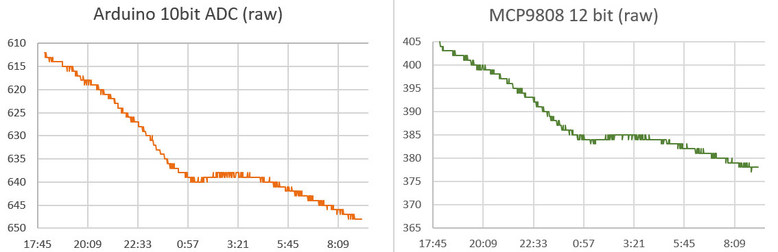
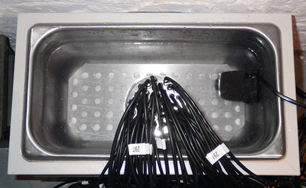
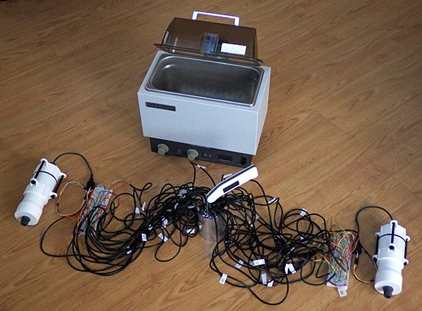
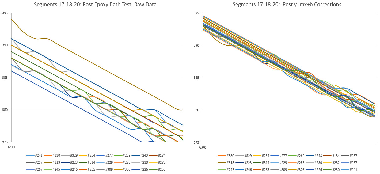
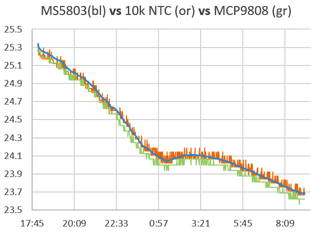
Thermistors are really twitchy due to their low thermal mass, so I did this test inside of a large ceramic pot with a lid to smooth out the changes.  At first bounce I though that jitter on the thermistor line was due to poor resolution, but it turned out to be an artifact of  the calculations I was doing in Excel.

When I compared the raw output of the Arduino ADC and the 9808:

Though the left axis is inverted for the thermistor, the scale on both is the same showing that the effective resolution is better than the 12-bit sensor. (click the image for a larger version)

Though the left axis is inverted for the thermistor, the scale on both is the same showing that the effective resolution is better than the 12-bit sensor. (click the image for a larger version)

So perhaps correcting the initial 3.3v VrefL offset reading with that Vcc ratio was not such a good idea, and I should avoid mixing different resolutions by taking a post 1.1v read of VrefL for offset correction.  Even if that is the case, tracking the positive rail still seems like a good idea for a data logger, so I will add it to the once per day events that get triggered by the 24 hour rollover.

So the job’s done with  four resistors and bog standard 10K NTC right?

Uh uhh… In fact this is just the stuff I had to get a grip on before starting my quest for the ADC holy grail.  I didn’t want something as good as the 12-bit sensors, I wanted something better, and the semi-mythical technique of oversampling promised to deliver all the resolution I could ever want from a humble Arduino… in theory

But this post is already miles too long, so for now I will just leave you with a teaser from a recent run-test showing output from an 24-bit MS5803 vs256 sample average using the Arduino ADC and that same 10k NTC thermistor:

Teaser_14bitditheredjpg

Y axis=temp in °C    Note: I have offset the curves here for easier visual comparison. The resolvable feature size is already well below 0.01°C and I am sure that I can push that a bit farther…

You have to throw in another resistor, and a couple of capacitors, and I still have some niggling details to work out optimizing the technique to use the least amount of power. When I get all that sorted, I will post the gritty details…

Addendum 2016-06-23:

There is a thermistor based Compost Sensor project by kinasmith at Instructables which uses wireless Moteinos and a cellular module to relay the data. Cool stuff.  Also there is a discussion of the lookup table method to address the accuracy of your thermistor readings (which I did not really talk about in this post) over at Mike’s Lab Notes.

Addendum 2016-08-01:

In this blog post, Ejo puts an ADS1115 / thermistor combination through its paces, using a combination of single and differential readings to remove voltage bias.  His resolution  reached 0.00427°C    And here is another group combining the ADS1115 with a bridge.

Addendum 2017-02-27:

Well it took a lot longer than I expected, but I finally got the post on How to do Oversampling with an Arduino out the door. The pin toggling method I’ve come up with is pretty darned easy, and gives you access to at least 4-5 more bits of ADC resolution.

Addendum 2017-04-26:

I’ve moved on to calibrating the thermistors, and in the process I learned that it’s probably not a good idea to combine the 1.1v aref, with the oversampling method. But I did it anyway.

Addendum 2017-09-26:

You could get another bit of hardware resolution with a two element varying bridge and then doing a Pseudo-Differential reading with the Arduino ADC.  I still haven’t wrapped my head around the math for that yet, which would get tricky if you were simultaneously using 1.1v aref – since your bridge could not be symmetrical.

Addendum 2019-03-25:

I’ve been developing a new method for reading thermistors with the Input Capture Unit on pin D8. Micro-controllers count time much more precisely than ADC’s measure voltage, so this new approach delivers more resolution than 16-bit oversampling in about 1/10th the time & power.

Field Report 2016-03-28: Oldest Generation of Loggers Retired

Securing the backup bungie cord to the anchor.

Securing a backup bungee to the anchor plate.

I know I said I was going to keep the ocean sensors in service till they croaked, but after more than two years of operation I’ve decided to retire the two beta units to our bookshelf museum. B3 & B4 were the last loggers in our fleet based on the Tinyduino platform (and the guys back in Ohio deserve some credit for helping us get the project off the ground!)  The clincher on this decision was the practical issue of still being able to do a full calibration on those sensors, so I can apply that to all that wonderful flow data we’ve gathered from Akumal Bay over the last 14 months.  And you run a risk of loosing your loggers every time you deploy in a high energy environment.

Four Generations of Cave Pearl Data loggers

Four generations of flow sensors, spanning two years of development. Beta4 was literally the fourth data logger I ever made, and the first to run for a significant length of time.

These replacements also bring all of the ocean units into the same generation of Rocket Ultra based builds,  so they should all deliver a year of operation before they need servicing. Much as I loved the Tinyduinos, I never got them down into the 0.15mA sleep currents that I now see the MCP1700 regulator  boards delivering.  As the folks at CEA keep pushing them further out onto the reef,  it’s getting more expensive to deploy & retrieve them, so we need all the run time we can get.

The new locations also mean I can’t just pop in and exchange them on the way to the airport… like I am doing today…

Addendum:
Akumal was the last stop on a busy trip that saw us hopping all over the peninsula to visit colleagues while staying in towns from Tulum to Chiquila.  You see allot of beautiful things outside the tourist strip that never end up in the brochures, but you never quite escape the influence that radiates from that heaving mass of transient humanity.

I think this is reflected in the work of the local artists:

Contrast

<— Click here to continue reading the story—>

Field Report 2016-03-27: Progress on the 1-Wire DS18B20 Temperature Strings

Happy to report the successful deployment of three more temperature strings:


and I think it’s fair to say the first two protoypes have almost run their course:

Logger/Sensors Time/Max.Depth Comment
#45  (19 x 25cm)
[1st build]
201503-08
(14m)
Full data from Temp chain, Qsil problem on pressure sensor
         (19 x 25cm) 201508-12
(6m)
Wire break on 1st segment before deployment: total read failure on temps, pressure data OK
         (11 x 25cm) 201512-1603
(7m)
Full record including pressure. Segment wire broke during retrieval. Brought home for refurb.
#46  (20 x 50cm)
[2nd build]
201503-08
(16m)
Full temp record. Pressure record problem.
         (20 x 50cm) 201508-12
(24m)
Full temp record. Pressure OK after Qsil removed.
        (9 x 50cm) 201512-1603
(24m)
3rd segment wire break during deployment dive. Nine sensors report OK for duration. Pressure OK. Failed segment removed & unit re-deployed.
#78  (24 x 100cm)
[3rd]
201512-1603
(16m)
Complete data record. Unit redeployed.
#79  (24 x 25cm,  & 10m extension)
[4th]
201512-1603
(16m)
Wire break during deployment dive. Full logs saved but no data. Failed segment removed & unit re-deployed w 18 nodes
These internal wire failures did not compromise the integrity of the outer jacket.

Fortunately none of these internal wire failures compromised the integrity of the outer jacket. These are only 7-strand wires, and I will be hunting for more flexible 19 strand replacements.

While it’s hard to see all that work deliver only a few successful deployments, I’m happy to note the failures were all at physical pinch points in the cable, with no other apparent problems on the housings or electronics.  And even when the wires break, the logger itself keeps chugging along: saving logs full of 1360 & -1 read errors.  Sensor problems like this often take a whole logger down, but the MS5803’s delivered data through every deployment, so failures on the one wire bus seem to be isolated from the rest of the sensors on the logger.

RIMG8849

Though it was always part of the plan, actually pulling off segment swaps in real time was pretty cool…

For existing builds, I reenforced the weak points with mastic tape

For the units in the field, I’ve re-enforced the weak points with mastic tape & cable ties to limit bending.

This is good news for me because physical problems are generally the easiest ones to fix…

Up to this point I’ve been using soft silicone jacket cable which is lovely to work with, but I will have to build the next set from sterner stuff.

Of course that means we might have to develop a new set of deployment procedures,  because handling 24m of stiff cable could be a challenge.  These deployments have already been some of the toughest dives on the project, especially when you get into the low-visibility hydrogen sulfide soup that Trish is so fond of…


The second generation builds also used less power than the first:

Much better power performance on the second generation of temp strings.

The battery curve is still a bit crunchy, but it looks like it might settle to about 100 mV drop per month at a 15 minute interval on 2x3AA’s.  That’s nearly the same as the first two loggers which had twice as many cells.  One of the things you notice about cheap DS18b20’s from ebay, is that they can draw dramatically different sleep currents.  This may be compounded by the fairly aggressive 2k2 pullup I use on the bus.


Spotted in Tulum:

Neighbours

Just finding a problem doesn’t always tell you how to fix it…

Field Report 2016-03-25: Collecting Data in Coastal Mangroves

Their never too young to be a field assistant :-)

They are never too young to be drafted as a field assistants… Eh Trish?

The unique geology of the Yucatan means that hydrologists like my wife typically study water flowing through the flooded cave systems.  But she also advises some of the many great archaeology projects in the area (The Maya had to get their drinking water from somewhere…right?) so we don’t spend all of our time wrapped in neoprene.  Though I have to say that when she does do surface work, she always seems to find the stinkiest stuff around to balance all that canned-air we would otherwise be breathing:

Smells like science!

We did eventually make our way to a wider section where the water was moving swiftly.  The original plan was to simply anchor one of the flow sensors on a rock and drop it in. But after mucking about at the site for a while, we were puzzled to see hardly any displacement on our little tilt meter though the surface flow was quite strong.  Then we realized that the water at our feet also felt warmer than it did on the surface, and it dawned on us that this close to the ocean, the tide was coming in underneath the outgoing fresh water.  The best solution I could come up with on the spot was to put the pivot joint on top of one of the pendulum rods: raising the flow meter to a higher position in the water:

We will have to wait for the data to see if we’ve given the logger enough height and The temperature should tell us if the logger has been trapped in rising salt water.  I would not be surprised if we end up using an entirely different arrangement next time, perhaps with some kind of floating buoy system so we can go back to a pendulum arrangement where the buoyancy is easier to control.  Sometimes all you get from your first deployment, is an understanding of how to do the next one…

BottomDeployment_600

Further in, we could put the logger right on the stream bed which had been scraped clean by the high water velocity. You can tell from the video (above) that we are well past 10cm/sec where vortex shedding starts to be a problem.

The next day we set out at a different river, working our way much further inland to (hopefully) avoid the salt water intrusion.  We also planted a pressure unit to capture water level data near the archaeological dig site.  Given how exposed these sensors are, I can only hope that the local fishermen don’t decide our little bots should spend the rest of their days decorating someones coffee table.

The water in these coastal discharges was racing by comparison to the gentle subterranean flows we usually work in, so I expect allot of turbulent noise in the signal. On top of that the removal of their salt-water ballast mass (used on pendulum installations) moved the center of mass enough that I had to put them in upside down. That’s just the kind of things you run into when you are doing something for the first time. With all the things we learned from the open ocean deployments, I’m really excited to see the Pearls moving into another new environment.

Addendum 2016-07-18

Well we finally made it back up to the north coast, to replace those upside-down units we left back in March:

Happy to report that the first deployment gave us good data, and I think this next crop will do even better, provided they don’t get hit by a passing boat propeller…

Addendum 2017-06-24

Believe it or not the unit was still buoyant, and gave us reasonable data.

After nearly a year we returned to discover that the stream-bed unit pictured above had gone AWOL, and the remaining two flow sensors were heavily encrusted with criters of all kinds. We’d seen bio-growth before on reef deployments, but never to this extent. To avoid further losses, the replacement sensors have been painted black and deployed in “stealth mode” locations.


Addendum: 

During these deployments we stayed in the fishing village of Chiquila.  I spotted this lovely graffiti during a morning run:

JellyFish

<— Click here to continue reading the story—>

Field Report 2016-03-17: MCP9808 Temperature Sensor Fails Under Pressure

Cave Pearl data loggers

In this shot you can really see how the addition of the drag flag amplifies the tilt signal.

Then next day saw some routine logger replacements at our favorite coastal cave. It’s relatively shallow, making it a good place for a shakedown dive, and we have plenty of air time to develop funky new underwater deployment procedures for our little bots.  The fact that it’s also an un-decorated mud pit is just gravy, as it means that no one bothers our instruments like they would in the prettier high-traffic caves.  Strong tidal influence also provides a good range in the data and this cave has been continuously instrumented since our alpha trials back in 2013.

Of course that also means this location has seen more instrument failures than anywhere else, and again it delivered some bad news with the good: showing that even a great sensor can eventually crack under pressure:

MCP9808 pressure failure brings down the logger

This logger had been performing well since mid 2015, and initial consumption curves indicated it should go a year or more on 3AA’s. But we had some hints in the last dataset that the temp sensor was struggling, and this time it burned through a set of batteries in less than six weeks, with the 9808 reporting imaginary temperature excursions very similar to those we saw from the TMP102 failures last year. Each was accompanied by a significant hit to the power supply, which would imply that we probably had some kind of pressure induced self heating going on inside the IC. (perhaps because of a short?)

The suspect MCP9808 (upper left). I have moved away from these large surface area sensor wells as I think they might be subjecting the sensors to larger bowing forces at depth.

The wonky MCP9808 after 9 months. On newer builds I have moved away from high surface area sensor wells as I think they might subject the sensors to larger bowing forces at depth. The LED also became flaky, with only the blue channel still operating.

That’s a bit of a bummer, because the MCP’s offer better off the shelf accuracy than most of the other temperature sensors in that price range.  So unless I want to put the breakout inside the housing, I’m forced back to the humble DS18B20’s that I used at the beginning of the project. I had a feeling this might happen, so on this trip we deployed a special 3-sensor cap on one of the loggers, with sensors inside the body, embedded in epoxy, and one projecting directly into the water. Hopefully that will let me determine how much lag we get from moving the temp sensors inside the pvc shell.  Since we typically don’t take readings more than once every 15 minutes, I’m hoping we don’t see much effect from the different arrangements.  During basement testing, thermal inertia rounded off short temperature peaks significantly, but that was at a five minute sampling interval, in air rather than water. 

Even with calibration you need some way to determine your mounting offset...

Even with calibration, you still need some way to determine the mounting offsets.

All three flow sensors delivered beautiful records, and the worst build actually  provided the best insight into the need for sensor calibration. Logger #69 had a 5° tilt error due to an adhesive failure during the build.  At that time I was still learning how to calibrate the sensors, so I was doing estimates of sensor mounting  offsets by simply averaging the readings from an overnight test where I hung the logger on a pivot joint.  The relatively large error on #69 meant that I almost rejected that sensor cap outright, but I figured we should put the unit in a high velocity site to test if it was still usable.   I later did a full calibration on that unit (with Magneto 1.2 software) to generate a more complete set of axes bias & scaling factors.

With the latest flow data in hand, I could now see how much difference the extra effort of full calibration makes:

TiltAngleCorrections

Those two corrected sets differ by a maximum of 0.5 degrees, implying that I can generate pretty good correction factors for older gen units in the field by simply hanging them in a closet over night. This also gives me a way to keep tabs on sensor drift without completely reprogramming the loggers, which I usually don’t have time for during fieldwork.

This is probably ‘good enough’ for our high flow sites, but for the deeper saline deployments (where the flows creep along in the sub-cm/second range) I’ll probably have to go full Monty since half a degree might be a significant portion of the total signal. And I have accumulated enough compass calibrations by now to show that in comparison to the  well behaved acclerometers,  magnetometer correction factors are all over the map with bias & offsets sometimes approaching 20%.


Spotted in Tulum:
TiltAngle

Working with a five degree mounting offset…


Addendum 2016-04-10:

Still processing the data from this last trip, and I found a good example from of one of those low flow systems, where the full calibration was needed to correct the axes bias errors:
Cave Pearl data loggers

Once you get down into the weeds, the factory offsets are larger than your signal, potentially hiding the phenomenon you are looking for. And you still have the challenge of filtering out the relatively high acclerometer noise, without destroying the more subtle tidal signals…

Addendum 2016-04-30:

I can only imagine what kind of incredible calibration challenges faced the people who made first direct observations of a gravitational wave, but I think I’m beginning to understand the sentiment behind this awesome tattoo…

Addendum 2016-05-06:

Hackaday just posted about an elegant new tilt sensor idea, using a variable differential transformer filled with ferrofluid. This principle of variable inductive cores has been used for years by YSI to detect salinity, but seeing this fellows approach makes me want the look at the technique again, if I can figure out a way to reduce the power consumption…

Addendum 2016-07-30:

We had another MCP9808 from that gen.  go down, but this time the power curve was the exact opposite of what I am used to seeing for IC sensor failures:

interesting power curve with temp sensor failWhile the sensor was throwing out a string of ‘Maximum Reading’ errors, the power consumption for the logger was normal. Then the sensor started delivering normal data again, but was obviously drawing enough juice to take the rest of the logger down quickly. Weird…

<— Click here to continue reading the story—>

Field Report 2016-03-16: Rain Gauges Over Reporting

Fer_RioExchange

As this was a dry part of the cave, I even risked bringing in the laptop…

One of the first priorities was a trip out to Rio Secreto to service drip loggers. Data from the last season confirmed that all of the loggers are good for at least 6-8 months, so we now have the option of servicing some units, while leaving others for a later trip. As the install base continues to grow, that’s becoming an important consideration for the trip logistics. Even so, our schedule was pretty tight so we decided to try servicing the units ‘in-situ’, so we only had to make one trip.

The forest floor gauge was knocked over by critters, despite a fairly hefty anchor.

Mapaches?

After that I tackled the climate stations we had on the surface. I was keen to see data from the logging rain gauges as this was only their second real-world deployment.  Back in Dec. we deployed two units, with one on the roof of a building, above the tree canopy, and one on the forest floor. My heart sank when I found that something had knocked the forest unit over, despite a fairly hefty cement anchor. That happened only a couple of weeks before our retrieval, so we still had a fairly complete data set.

Our original thought was to use the comparison data to see how much rainfall was being intercepted by the canopy, but the sheltered forest floor record also ended up providing me with some vital information about how wind was affecting the rooftop unit:

F

TypicalDailyWindNoise

The ground unit had none of these 0-15 count spikes which peaked at mid-day (local time).

The drip counter inside the rain gauge is essentially using it’s accelerometer as a vibration sensor, which gave us in-cave sensitivity down 12cm drip-fall distances. So it probably should have occurred to me that we needed to reduce the sensitivity for surface applications.  The daily noise is pretty easy to threshold away in Excel with an if statement [ =IF(DataCell-threshold<0,0,DataCell-threshold) ] and different settings showed that the typical daily ‘background noise’ was adding about 10%.  I’ve even heard that funnel wetting & other losses cause cheap rain gauges to under-report by that much, so this daily bump might come out in the wash.  A thornier problem lies with the ‘windy day’ events, which produce the larger spikes. And that effect is probably embedded in the rain storm data as well.  Though with ~10 drops counted per mL of water through our funnel,  actual rain events usually count up into the thousands.  So I can apply pretty aggressive filtering (with thresholds around 200) and doing so hints that the stronger wind events are probably adding another 20% to the overall totals. I know that’s sounds pretty bad, but hey – it’s a prototype right?

So there are a batch of sensitivity trials ahead, and once again I need some external data to calibrate against.   Of course anything that can count accelerometer alarms can just as easily be counting reed switch closures, so it’s back to the bench I go… 🙂


Spotted in Tulum:

Signal2Noise

Signal-to-noise ratios…

<— Click here to continue reading the story—>

DS18B20 1-Wire calibration with Arduino: Finally nailed it!

Dry well insert for DS18b20 calibrations

The Thermapen tip fits reasonably well into a 9/64″ hole, and that size also makes a good pilot hole for the 1/4 inch DS18 wells. The travel on my little bench-top drill press is only two inches, but that turned out to be the perfect depth.  The whole job took about 4 hours, with less colorful language than I was expecting.

The high residuals I was seeing up at 40°C, and the dubious waterproofing on those cheap DS18b20‘s convinced me that I needed a dry well for the calibrations. Since lead has a thermal conductivity 100x better than water, my first though was to populate a tin can with short lengths of copper pipe and fill the spaces in between from my solder pot.  But I was unable to find exactly the right internal diameter of piping for the tight fit I wanted around those sensors, and the charts indicated that aluminum would give me 1/2 an order of magnitude more thermal distribution.  So despite the fact that I had no experience working metal like this, I ordered a 4″ piece of lathe bar stock from eBay (~$15).


CirculationPump

Go to a 530GPH pump if you have a larger water bath. The aluminum and stainless steel contact point suffered a bit of galvanic corrosion at first, but I separated them with a plastic plate and it seemed fine after that.

It took me a while figuring out how to lubricate the bits: basically you can never have too much cutting fluid at small diameters, but you can use the big 1/4″ bits ‘dry’ once the pilot holes are in. Just lift the bits frequently to clear the shavings so things don’t heat up and bind. And yes, new high-temp drill bits will cost you more than the aluminum rod – but it’s worth it. The 3″ diameter rod gave me enough room for 38 DS18’s with a few different locations for the Reference Thermapen probe. The next addition to the process was a 1200L/h aquarium pump (~$8), which created a vigorous circulation in the five liter reservoir.  So now I have a setup were the clunky old water bath provides a big lump of passively cooling thermal mass, while the sensors and my reference thermometer are held together by the conductivity of the aluminum block.

The full DS18b20 calibration rig, with ~10x1m sensors in what is essentially a star configuration via the intermediate breadboard. 2k2 pullup resistor.

With those new additions, re-running the 100-ish sensors I had on hand produced curves so smooth that it was easy to spot my own procedural errors ( when I did not wait long enough for the Thermapen to equilibrate ) because the DS18 curves had considerably less of the random scatter I had seen in the water-only runs:

BadReadings2

After removing the bad reference readings I generated the same series of y=mx+b fit equations as before, only this time I did not use a graph trend line to generate the constants (described in the previous post) but instead used the slope & intercept functions in excel. This lets you copy and paste the equations from one data set to the next with a macro which dramatically speeds up the process when you are chugging through more than thirty sensors at a time. It also adjusts & recalculates dynamically when you delete a row. Convert your reference thermoenter readings from Celsius into the equivalent 12-bit DS18b20 reading by dividing by the DS18’s resolution of 0.0625C

Now that the sensors were really were being exposed to the same temperature, I could use the raw and corrected residuals to prune the reference data even more by rejecting any single reading anomalies that made it through the first pass: ( residual(s) = reference – DS18 reading)

BadReference2

It’s quite an improvement to be able to use the DS18 output to polish the set because in previous tests (without the dry well) the high temperature residuals were so variable that it would have completely masked this kind of problem.

Using the groomed reference points,  it’s easy to see which sensors make the cut:

Criterion used to select sensors for DS18b20 sensor strings

With LSB points on the y axis of those graphs, the corrected residuals for a good sensor fall into a tight band between ±0.5 LSB. The bad sensor on the right has a huge spread, and was immediately tossed in the garbage.  In theory at least, I’m achieving calibration accuracy better than the sensor resolution of ±0.0625°C.  It would be a bit bravo to claim that, but I am confident that we reached the ±0.1°C target that I wanted for our field sensors, without doing a full laboratory level temperature sweep

Grouping the DS18b20 sensors into more refined categories

With only one or two exceptions, these sensors under-read. Of about 100, the largest group was (-3 to -5) LSB points with 12 sensors, followed by (-4 to -6) with 11 sensors. A small handful of sensors had consistent offsets with no slope, and only two sensors had positive slopes in their raw residuals. Overall, I rejected about 30% of them for one reason or another. To get really sweet sets, it’s a good idea to start your project with about twice as many sensors as you think you are going to need, from 3 or 4 different vendors. (though the ones from Electrodragon provided the highest yield…)

Another benefit of all this work is that I can now group my sensors using the raw residual trend-line values at both 20 & 30°C. (see top left graph for #328 above) This captures both the offset and the slope information, and by matching slopes I can assemble strings of sensors who’s uncorrected behavior does not diverge.  With the calibration corrections already in hand this might seem unnecessary, but experience has shown that being able to quickly spot trends in the raw data can be very handy in the field when you need to make on-the-spot decisions about a deployment.  I can also add that the sensors from different suppliers showed strong clustering in these groups, implying that production run biases would introduce an offset into group normalization methods (ie: without a reference thermometer to compare them to) unless you bought them from several sources.

So our temperature chain system is maturing nicely, and in a pattern that is becoming familiar, it took three generations to reach the point where I think my DIY builds could be compared to commercial kit without looking too shabby:

As time goes on I am reducing the number of interconnects, but even with longer chain segments I will probably stick with only 24 sensors per logger.

As time goes on I am reducing the number of interconnects to improve reliability. But even with the chain segments sporting more sensors, I only put twenty four nodes on a given logger body.    As my wife already calls the all white flow sensors ‘storm-troopers’, I added a touch of ‘vader black to spruce up the housing.   Hopefully, the force is strong in this one  🙂

Of course these guys still have to prove they can last a year under water, so for now we will continue with dual deployments (which we usually use for new prototypes) in case one drops out on us.  

I’ve only got solid power usage data from one of my 24 sensor chains at the moment as everything else is still out on deployment. On those early units, I had no idea what the total usage would be so I just packed in 12 AA’s. (4 banks x 3 in series) After the over-voltage burn down, the discharge curve settled to a steady 100mV drop per month. That unit had 24 sensors, taking 12-bit samples every 15 minutes. My current builds have only 2x 3AA banks, so I expect them to drop by about 200 mV per month. A low input cutoff of about 3.4v on the regulator means that I will probably get 5-6 months out of a fresh set of six AA’s.  Driving the DS18’s at their maximum resolution (ie: 24 x 1.5mA x 750ms =~27 mAs /sample), I think we would only make a year on 3AA’s if I moved the interval out to once per hour.

With respect to quality, the real test will come in post deployment testing when we find out how much these sensors drift over time.  And I am really keen to see how the units we deployed across that hydrogen sulfide layer performed, as that chemistry is far from benign.  If they prove hardy enough, we might even bury a few and see how that goes.  In harsh environments, every choice you make in the build is a cost/time-to-failure trade-off.

Addendum 2016-03-07

[jboyton] over at the Arduino.cc sensors forum pointed out that you could save the $200 cost of the Thermapen by using an Ultra Precision Thermistor from U.S.Sensor that offers ±0.05°C accuracy right out of the box. These 10K NTC units can be purchased from Digikey for ~$10 each. You could epoxy that sensor into the same stainless steel sleeves used on the DS18’s and be ready to go. The cool thing about this idea is that the reference readings could then be taken on a logger, avoiding those mistake-prone manual readings. Definitely going to look into this …

Addendum 2016-03-10

I’m doing post assembly water bath checks on the T-chains now. I had some lingering questions about whether epoxy contraction, or the heat I used in the process of making the string nodes, would throw off the calibration:

#74 was included in this group by accident....grrr

#74 was included in this group by accident…

You can see how closely matching the 20 & 30°C offsets groups the raw readings into a fairly tight 3-point band even though the sensors are now distributed around the water bath.   Applying the linear correction reduces that to 2pts, and shifts them all up towards true temp.  With the spread approaching the bit-toggling level I suspect I’ve reached the point of diminishing returns, so I’m calling this set ready to deploy without further normalization.

Addendum 2016-03-11

Segments 19 & 20 were constructed with some of the most stable sensors from that round of calibration, at least with regard to the corrected residuals.  But I did not have any other groups large enough to build the next few sets from DS18’s with identical performance,  so I loosened the criterion out to ±1 LSB, and started combining different offset groups on the same chain (mixing the sensors randomly so no trends would be introduced…)

The mix ended up producing graphs like this:                        (click images to enlarge)

Cave Pearl data loggersThe raw variability now crosses 10 points, and after you apply linear calibration you are still left with a 3-4 point spread depending on where you are on the curve.  So while the group as a whole should still be accurate, I now face a question of precision. Having those sensors flop around by as much as ±0.15°C could mask some of the more subtle signals we are looking for, and this forces me to apply a round of group-normalization to get them into the kind of tight band I saw from the prime sensors:

Cave Pearl data loggers

This second Y=mx+b correction is based on the average of the post calibration readings (so should have no effect on the accuracy) and you can still see some spaghetti squiggles from the inherent noise in these b-class sensors. I was hoping that the new method would save me from having to bang ’em together like that, but apparently it depends on how fiercely you apply your selection criterion before getting out the epoxy.

Which reminds me that automating the calibration run (ie: using a high accuracy thermistor as the reference) would let me test many more sensors and build those matched sets with less time playing button-monkey. Of course, I’d also have to ensure that I’m not introducing other errors in the process with the way I handle the thermistor readings…

Hmmmm…

Addendum 2016-06-29

Now that I have several more of these temp. chain loggers under my belt, another issue has popped up that could be taken care of easily at the calibration stage: Sleep current.  Sensors from some of the eBay vendors draw significantly more than the 750nA standby listed in the spec sheet.  A ‘good’ set of DS18B’s doesn’t add significantly to your loggers sleep current, but a couple of lemons in the batch can raise a 12-node segment to between 0.1-0.2 mA for the sensors alone.  This might explain how these cheapies get onto the grey market in the first place.

Addendum 2016-07-03

With the next generation of temp strings in production, I am still wrestling with the “diverse” sets assembled from sensors with widely varying behaviors.  These continue to need a post-calibration normalization round to bring the group behavior together:

Cave Pearl data loggers

What’s twisting my melon is that it’s hard to know how much of the post-cal normalization is actually beneficial, and how much of it is just compensating for differences in water bath, since the post epoxy sensors are no longer pinned together by that block of aluminum…?

Addendum 2016-11-16

Just a quick note to suggest another step to overall procedure: Measure the sleep current of your DS18b20! Good ones auto-sleep at about 1μA, but I’ve had a few batches now that constantly draw between 40-60 uA each.  This flaw was definitely vendor specific, so only buy a dozen or so from each to test them out before buying a large bunch. So far, I’ve had the best sleep currents with the $2.50 sensors from electrodragon, though their “waterproof” epoxy job is utterly pathetic, and the raw 20 & 30°C offsets are often just barely within the ±0.5°C spec. Also I have modified the script I use to gather the serial numbers so that it automatically sets the sensors to 12 bit every time it runs. That is the default resolution, but I found that one or two sensors from a given batch arrive set for lower bit depths. And finally, watch out for sensors that require parasite power turned on at the end of the conversion to operate properly even when they are being powered by all three lines. (ie: needing oneWire.write(0x44 ,1);  rather than oneWire.write(0x44); )  I have never gotten parasite and normal mode DS18b20s to work properly as a mixed bunch. Stick with normal mode.

Addendum 2016-12-04

Usually I do these calibration runs with sets of 32-34 sensors, so all the holes in the aluminum block are filled. But I recently tried to calibrate a small batch of eight “naked” DS18b20s with the same method, and ended up with slope and offset calibration factors that were 1-2 degrees Celsius too low, as compared to my reference.   I re-ran the cooling ramp with tape over the unused holes, and sure enough, the adjustments became much smaller, with the raw readings much closer to the reference.  Air was getting in and cooling the center of the block where the sensors were. So if you use this method on a smaller numbers, use other DS18’s to plug up all the unused holes, and put tape over the used ones to prevent air circulation from depressing the readings for raw sensors.  I hadn’t thought about it earlier, but the sensors themselves form part of the thermal mass of the system.  Once you start calibrating, you will have more than enough ‘duds’ (with the cables cut off) to plug up those wells when doing a runs with smaller numbers of sensors.

Addendum 2017-01-18

I just stumbled across a paper at MIT that makes it pretty clear that I’ve been reproducing a standard method already on the books. I’m still digesting the information, and there is lots of stuff in there about handling sensor frequency issues, but I figure most of that has been damped out by the oversampling in the DS18, and by the epoxy around the sensor nodes.

Addendum 2017-01-24

Using shower combs to separate sesors in the calibration bath

Shower combs from the local dollar-store worked well to keep the sensors separated.

We retired a few early generation temp. strings during the last round of fieldwork, and many of those had been deployed before I had a good calibration process. But we had months of data from them, so I now had the challenge of calibrating these sensors after the strings has been assembled.  With 24 sensors per chain, they amounted to  pretty hefty lump, and it would take some work to make sure they were all exposed to the circulating water bath properly. Some large combs provided the needed separation, and I mounted a 330Gph circulation pump near the center of the mass.

Cave Pearl data loggersSo now I could use the waters cooling curve to do a decent  normalization, but calibration with the was going to be tricky because of the thermal inertia of the epoxy around those sensors. I found a dead sensor from one of my early experiments, and drilled it out as a mount for the Reference Thermapen probe, providing it with approximately the same amount of lag as the sensors on the strings.

postdeploymentcalibrationThe loggers recorded readings every 5min over 24 hours, for the group normalization (y=mx+b) coefficients . I did manual readings with the Thermapen every 30minutes which provided at least one reading per degree as the bath dropped from 35°C to 20°C.  For that T-pen subset, I produced a second set of y=mx+b coefficients that corrected the group average used for normalization,  into the reference temps.  So the order of operations is reversed when compared to procedures that start with calibration of the raw DS18b20’s, but I’m happy to report that the process worked rather well, turning some jagged old data sets into smooth temperature profiles that compare very well to Hydrolab drop profiles from those same sites.  In fact it worked so well, that I think I will do it with every chain that comes home, with a careful eye on the chains that had a decent calibration as individual sensors.  I’ve seen plenty of pressure related problems in my other temp sensors, so I do wonder if the contraction of the epoxy is enough to hurt those initial calibrations?

Addendum 2017-04-28

While I like the $200 reference Thermapen I used for this calibration (and the NIST certificate that comes with it…) that ±0.04°C tool is probably out of reach for many DIY builders.  I recently discovered the Silicon Labs Si7051 at Tindie for $9, which gives you 14-bit resolution of 0.01°C at ±0.1°C accuracy. I’ve been using these I2C sensors to calibrate 5% thermistors  to better than ±0.2°C by baking all the system voltage errors into synthetic Steinhart-hart constants. That’s pretty good considering that the eBay thermistor and the reference thermometer together, cost less than a high quality thermistor.  I still have other details to work out before I’m building temperature chains with thermistors, but I don’t think I’ll be able to resist that temptation for long…

Addendum 2017-09-04

Just noticed a nice DIY dry bath over at instructables.com. Though I’m not sure its accurate enough for calibration, you could still use it on the “natural cooling curve” side like I do with my wet/dry method. I’m sure there will be more good calibration kit coming out of the bio-hacking boys soon and they did some beautiful DS18b20 calibrations over at http://www.kandrsmith.org using the melt plateau of 99.99% gallium.  And here’s an interesting “exposed” epoxy mounting of DS18b20’s in a liquid-cooled system.

Addendum 2020-04-07

Given how hard we have to work to bring DS18b20’s into line, I’m quite surprised to see someone using them as a reference standard. Also had no idea that K-type thermocouple sensors were so darned noisy – much worse than plain old thermistors. I’d be oversampling the heck out of those things, along with extremely vigorous circulation in that bath. Air calibrations? Fuhgeddaboutit.