
This post is a summary of my background research into electrical conductivity to serve as a backdrop for my own humble attempts at this interesting measurement challenge. I’m sure there are many other approaches that I’ve yet to discover, and if you know of one please leave a comment so that we can pass that knowledge on to others – Ed.
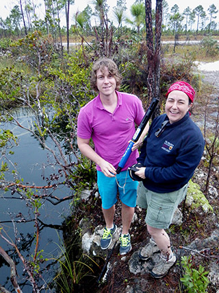
Pete & Trish doing profiles with a YSI EXO. As you might imagine, these puppies are pretty expensive. Now that we have A Flexible Arduino-Based Logging Platform to build on, adding conductivity is our #1 priority. Creating a good drop-profile is an incredibly slow process because you have to wait for the probes to thermally equilibrate and you don’t want to disturb the delicate halo-clines as you pass through them. The last 35m profile I did with a Hydrolab took 2 hours to reach bottom.
The conduction of current through a water solution is primarily dependent on the concentration of dissolved ionic substances such as salt. Since most fresh water derives from relatively clean rainfall, variations in EC provide a way to track the chemical and hydrological processes the water has been subjected to over time. High amounts of dissolved substances (usually referred to as salinity) can prevent the use of waters for irrigation and drinking, so conductivity ranks as one of the most important inorganic water quality parameters.
A huge number of resources are dedicated to measuring EC and rather than re-hashing all that material, I thought I’d start with links to a few good background reads:
Conductivity, Salinity & Total Dissolved Solids
-discusses the older TDS measurements in parts per million ( ppm ) which makes assumptions about the charge carriers that don’t reflect real world environments. The conversion factor from EC (which is the thing you actually measure) to TDS changes for different dissolved solids, so instruments from different manufacturers often give you different TDS readings for the same solution, because the companies made different assumptions about what’s in your water. Because of this confusion, straight EC measurements in siemens have been adopted as the standard by the international scientific community. One siemens is equal to the reciprocal of one ohm (S = 1/Ω) and is also sometimes also referred to as the mho (℧) in older literature.
Conductivity Theory & Practice
-a white paper that covers basic probe designs, and mentions some non intuitive things like geometry/field effect errors.
Conductivity Sensing at PublicLab.org
-many groups at PublicLab.com have been working on different types of conductivity sensors and their overview page is another excellent introduction to DIY approaches. In fact it’s so good that I will be referring to several of those projects in this post.
Aqueous conductivity is commonly expressed in millisiemens/cm (mS/cm) and natural waters range from 0.05-1.5 mS/cm for freshwater lakes & streams up to about 55mS/cm for sea water. Water up to 3 mS/cm can be consumed, though most drinking/tap water is below 0.8 mS/cm. Many of the Cave Pearl Project’s installations are in coastal areas where tidally driven haloclines require our instruments to cover that entire “natural waters” range. Groundwater can vary even more, with measurements being complicated by organic acids and/or significant amounts of dissolved limestone. Salt water is chemically aggressive and water hydrolyzes above 0.4v, so the probes for high-conductivity environments are usually made of resistant materials such as platinum, titanium, gold-plated nickel or graphite, making them somewhat expensive.
Ways to Measure Conductivity:
There are so many different approaches to measuring EC that it’s taken me a while to digest it all into some working categories. I expect to build at least one prototype for each of these methods just to see if I can make it work.
Density Based Methods
Refractometers and density based hydrometers are used by aquarium hobbyists. Better quality acoustic doppler flow sensors can also calculate density based on the speed of sound through the water and infer salinity from that. Given then number of acoustic anemometer projects out there, I’m surprised someone has not already adapted the method for underwater applications, though this may be due to the timing limits of the affordable transducers.
Resistance Based methods:
a) Use submerged probes as part of a resistor divider / bridge :
 This common approach measures the resistance between two probes using some type of voltage divider. Resistance =1/conductance, which allows you to derive conductivity with your cell K constant since conductivity=(conductance * length)/(area). AC oscillators are tacked on to reduce electrode polarization, and this forces you to add even more electronics on the output side to convert the signal back to DC for reading. The resistance between the probes changes by several orders of magnitude in environmental waters so different probe surface areas & divider resistors are usually required to cover a significant conductivity range. Above 50% sea water, the resistance between the probes doesn’t change very much, so this method tends to get used more frequently for fresh water environments.
b) Change the pulse frequency of a 555 timer circuit:
You can use resistance between the electrodes as part of an RC relaxation oscillator and then measure the 555’s square wave output frequency to determine the resistance.
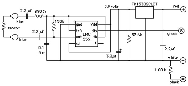
This circuit from Thomas Allen’s site provides galvanic isolation, uses AC measurement, and the output frequency varies from about 42 Hz with the probes in air to > 8000 Hz depending on conductivity. You can buy this circuit on pre-made a module for $24 from the EME site.
Circuits and instructions can also be found at at PublicLab.org and there are many good tutorial videos describing 555 based EC sensors on YouTube. At this point I’ve run into so many projects using this chip that I’d be willing to bet every environmental sensor I’ve ever heard of could be cobbled together from a few op-amps and a low voltage 555 timer . There are several frequency counting libraries available to help you get started, and if you are ready to sink your teeth into some code, Nick Gammon has produced the some elegant solutions for pulse/frequency timing. Note there are some duty cycle issues (also see: Schroeder Thesis)
c) Time the discharge of a capacitor through the solution:
Jim Conner’s describes this method in his youTube video at
EC Probes – How they work, and how to build one

A circuit like this might be easy to implement on an Arduino if you can put the internal 1.1v reference onto the comparator that’s also built-in to the 328. Microcontrollers count time with far better resolution than you get from their ADC’s, but that doesn’t mean there aren’t other issues to deal with. Given that you can try this method with practically no extra circuitry, I will definitely be prototyping a few of these. Like the 555 based circuits, it will be interesting to see if the method bumps into timing & interrupt handling limits (100 kHz?) when you use it with seawater.
Capacitance based approaches:
You often see capacitance used for liquid level sensors and soil moisture probes, and some of these could be adapted for EC. To me, the raindrop detection pcb’s you see on eBay have always looked like prime candidates for re-purposing as capacitive sensors.
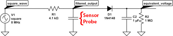
The circuit described for the Chirp Moisture Sensor uses a fixed resistor and a probe made from PCB traces to create a low pass filter whose cutoff frequency changes with capacitance, which is affected by the material around the probe surface. This filters an 1-8MHz square wave and the output voltage is accumulated other side of simple diode peak detector circuit for reading. Cheaper versions of this sensor use a 370kHz square wave at the input end which is about the fastest pulse you can get from a cheap 555. Unfortunately that’s not quite fast enough for most salinity work which usually works with MHz.
You can also vary 555 timer output frequency by changing the capacitor in the tank circuit, or create more complicated oscillator circuits. No matter which cap-based method you use, the supporting electronics have to be located near the sensor – because just about any length of wire will add enough stray capacitance to throw off measurements. Because you need large resistances to compensate for the small (50 – 500 pF ? ) capacitance of the probe, you are essentially creating an antenna. Unfortunately pF levels are too small for the traditional charge/discharge timing methods which work so well in the nF to uF range.
The resulting RC filter time constants make these methods much more suitable for the air/water application which changes the probe capacitance by almost an order of magnitude (50-400pF) , with more dissolved ions acting like wetter soil. Once the probe is submerged the output delta for fresh vs salt water with the RC filter approach is MUCH smaller. (say 400pF to 450pF …ish?) Using the probes capacitance as part of an LC oscillator would give you better discrimination of small changes, as MCU’s can count frequency reasonably well.
Another thing to keep in mind with the RC filter method is that common ceramic capacitors have some of the worst thermal coefficients and aging effects imaginable so your pulse source is likely to drift as well. Plastic film capacitors using Polyphenylene Sulfide (PPS ±1.5%) or Polypropylene (CBB or PP ±2.5%) have much better tempcos, and having a digital capacitance meter on hand is probably a good idea, though most won’t even measure down to the 1pF range you’d need with small probes.
Potentiometric (4 electrode) Methods
Four-electrode cells uses two “driver” pins to place an electric field across two other “reading” pins that lie between them:

This paper describes a DIY 4-probe sensor that was used for soil moisture sensing, and you will find quite a few articles using potentiometric methods over at IEEE and Sensors ALSO see Design of sound speed profiler -Water Parameter Sensor (2017 Master thesis) by Shaban, A, University of Oslo – which describes building a four electrode sensor with Arduino
Nokia/Apple audio jacks came to mind as soon as I saw this diagram, and they might be available with gold plating. 4-electrode methods often measure the voltage between the read pins, which is divided by the exciter pin current to determine the solution’s impedance = 1/conductance. To obtain the conductivity, the conductance is multiplied by the cell constant of the inner poles. Tracking the pin current lets you compensate for fouling on the plates, and the method can cover a wide range of conductivity. Like inductive methods, this approach tends to work better as the concentration increases.
Inductive Methods
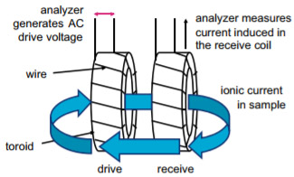 The conductivity measurement is made by passing an AC current through a toroidal drive coil, which induces a current in the solution. This induced solution current, in turn, induces a current in a second coil, called the pick-up toroid. The amount of current induced in the pick-up toroid is proportional to the solution conductivity. You get industrial grade performance out of this non-contact method in many different types of solutions, but you also need industrial amounts of power the drive the sender coil so it’s hard to implement on the kind of power constraints you see on stand-alone data loggers. Inductive sensors require a 3 inch radius from any other surface (bio-fouling?) and you see this pretty clearly in the ‘donut on a stick’ sensor heads. It occurs to me that you see very similar components in a wireless charging system, but there’s a lot of devils hiding in those details – like shielding, etc. It might be possible to press one of the production line proximity sensor chips into service for a low power solution, or simply try measuring changes in inductance due to the presence of salt water.
Off-the-shelf Solutions for Arduino: (using 2-Electrode Resistance Methods)
 |
|||||
|---|---|---|---|---|---|
 |
Atlas Scientific Conductivity Kit A complete solution including calibration solutions, a range of probes and code libraries. All parts also sold separately: interface boards are ~$35 & EC probes come in around $120 each but they are durable enough for continuous long term submersion. I2C data transfer is supported, so resolution is not limited to the Arduino’s ADC. Whitebox labs Tentacle Shields ($35-$110) provide up to four galvanically isolated channels for full hydroponic rigs. Stand alone BNC carriers for $10. The notable Open CDT project makes use of these sensors. See Jonas Auråen’s Thesis for a comparison of Atlas sensors to a commercial CTD. |
$200 | |||
| CN0349 Conductivity Measurement System The EVAL-CN0349-PMDZ has total error less than 1% FSR after calibration. The digital output is fully isolated eliminating ground loop interference. Even if you are using a different circuit at the sensor, its work looking at how they did that. Thanks for the tip about this one from Joshua Girgis: “Its designed to work as a benchtop sensor but one can easily wire it up to the i2c lines on an Arduino. The code is a little cumbersome but I have it working for taking temperature and conductivity measurements for sea water.” Update 201907 : Joshua has released an Arduino library for this board on his GITHUB. |
$45 | ||||
 |
Gravity: EC Sensor Kit for Arduino (K=1) Another complete K=1 kit solution, but the probes are not robust enough for long term submersion so several people replace the stock probe with the 208DH which is available on eBay for $35. Arduino ADC reads voltage. The KnowFlow project uses the full set of DFrobot boards. DFR also has an inexpensive TDS kit, which cfastie has been testing over at publiclab.org |
$70 | |||
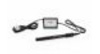 |
Vernier CON-BTA EC probe This 5v K=1 probe covers 0-20,000 μS/cm in the high range, and the analog voltage output is read by the Arduino ADC. You need an inexpensive adapter board for the BTC connector, and they provide a basic library. One key feature is built in hardware temperature compensation with a 10k thermistor in the probe head. My tests show this reduces the usual 2% / °C reading variation down to about 0.5%/° C, so you still need to do your own calibration to get higher accuracy. Like Atlas Scientific, Vernier has many other interesting sensors that are Arduino compatible. (Much cheaper on Ebay for older stock) |
$115 | |||
| EC/pH Transmitters This company offers a range of physically bulky turn-key solutions, with the $70 entry level unit claiming 0-5000 μS/cm (fresh waters) and continuous monitoring. Arduino ADC reads voltage. ~$200 units support PH with isolation. |
$70-250 | ||||
 |
Sparky’s widgets MiniEC An indie who makes several other useful sensor breakout boards, including PH. You have to build or locate your own probes, though they use a standard BNC connector like most EC probes. Arduino ADC reads voltage output. Works with many of the inexpensive probes you find on Alibaba – some of which look remarkably like the probes used by Atlas? |
$24 | |||
 |
EC-Salinity Probe Interface by Ufire Designed around an ATtiny configured as an I2C slave, probably using the cap-discharge method. |
$14.50 | |||
 |
Hanna HI 73311 (K=1) Replacement probes In the past we’ve used used these epoxy&graphite probes from Hanna DIST5 (HI 98311) and DIST6 (HI 98312) testers, which connect to a standard male audio jack. You can also re-purpose one of the Vernier ABS/graphite probes if you get a used one cheap on eBay, and the Vernier probes have a 10k NTC thermistor built in, which you can read with a divider. The best completely DIY probes I’ve ever seen are the concentric electrodes built by Camilo Rada with epoxy & graphite rods. |
$55 | |||
 |
Comercial Standard Solutions For fieldwork, it’s often easier to transport the dry packets, and mix them on location. Atlas sells calibration sets, but at the twice the cost of standards when you buy them in larger volumes. You can find recipes for homemade calibration solutions at Reefnet Central and PublicLab. For a classroom situation, it’s much cheaper to mix secondary “lab standards” in larger quantities, and then test the resulting solutions with a commercial probe that’s been calibrated against commercial solutions. 5.566g of dry NaCl in 1 litre of distilled water will create an ~10,000 μS/cm solution, which you can dilute down for lower concentration standards. |
$14/500ml | |||

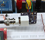
This photo from Bitnitting gives you a sense of the physical space needed for the Atlas breakouts and a ‘mini’ form factor Arduino.
Hydroponics hobbyists have putting these kits to good use over the years with notable examples like the long running forum thread on Billies Hydroponic Controller, and the well documented adventures over at the Bitnitting Blog. The people at OpenCTD and other academic projects have put the Atlas boards into real world deployments.
But to me these commercial solutions still leave you stuck with those expensive electrodes which sometimes cost more money than you would pay for a used 4-pole device. More annoying is the fact that those cell constants do not line up with my goal of measuring the entire “fresh” to “marine” range with one sensor, thought if I could extend it a bit the K=10 probe comes close. This is illustrated by the following graph from Andy Connelly’s Blog which is worth digging through as he has posted lots of other interesting material on calibration, reproducibility, signal detection, etc.

Of course the cell constant changes as your probes get older and dirtier, so you have to re-calibrate them with standard solutions just about every time you want to take a new reading. I’m pretty sure I will end up making my own probes, probably out of Nichrome 80 wire as the vaping fad has made it common on eBay. Some have had good EC results with gold plated PCB traces. Feedback on the Arduino.cc forum suggests that Platinum-Rhodium Thermocouple Wire is another good option. I’ve also been wondering about Ag/AgCl which is highly resistant to seawater and is commonly used for non-polarizing electrodes in medical/bio applications. (EKG electrodes?) It might also be a good idea to cobble together a DIY magnetic stirrer, based a PC fan and an old hard drive magnet.
DIY 2-Probe EC Circuits
The easiest circuits to build yourself are the 555 timer oscillators, but there are plenty of quad-opamp solutions out there for people comfortable with a breadboard. The oldest example I’ve seen is this one by M. Ahmon from the Sept 1977 issue of Electronics magazine which uses the resistance of the solution to modify opamp output:
 This circuit uses the first stage of the quad opamp in a Wien-bridge oscillator, reducing errors caused by electrolysis with a 1-kHz signal that gets attenuated by the solution’s resistance before it reaches the driving amplifier A2. Pot P1 controls oscillator amplitude, and P2 adjusts gain of A2. A3-A4 form a precision rectifier giving output voltage equal to absolute value of input voltage. This one chip solution seems to have been the basis for many of the current EC projects on the web, including these two exceptionally well documented examples:
Octavia’s EC/TDS/PPM Meter On Limited Budget
Daniel Kramnik’s Digital Salinometer Project

 Similar circuits can be found on the breakout modules from Sparky’s Widgets and DFrobot . Using the solution’s resistance in the feedback divider controlling an op-amp is a neat idea, but having only one opamp there imposes hard limits the range you can measure with a given K value probe. There is a more advanced multi-opamp approach over at pulsar.be that can step over several decades.
On more recent EC projects I’m seeing single supply RRIO opamps for the oscillator & gain stages, which are easier to integrate with battery operated Arduino’s. (though any dual supply opamp can be used as a single supply in a pinch; since voltage is relative the opamp doesn’t know whether V- is a negative voltage or ground) To keep using an AC signal, this requires a virtual GND at 1/2 VCC, but the integration also gives you the option of getting rid of the oscillator entirely, since you can use PWM output as your source.
This is beautifully illustrated by the circuit from bhickman’s Conductivity & Temperature Meter over at PublicLab:

Ranging is accomplished with the (red) bank of R1 resistors, and (yellow)R2’s 5/6 can be substituted in for the probe (R8) with those known resistances can be used to track drift. The AC–DC converter stage is built with precision peak detectors. I think this is the best voltage divider approach I’ve seen to date. To simplify things a bit, you might replace that output stage with an RMS-DC converter; though I’ve not seen any breakouts for those, and I hate working with raw SMD parts.
Sources of Error:
 Even with a clever circuit like the one above you still need to address things like temperature compensation before you get an accurate, repeatable, and stable device. Electrical conductivity measurements are typically referenced to 25 °C using standard temperature compensation factors (α). The conductivity of natural waters exhibit strongly nonlinear temperature behavior, though in practice linear correction factors are most frequently used. NaCl-based solutions typically have a temperature coefficient (α) of 0.02-0.0214 (~ 2% change/degree C). So to convert your “ambient” conductivity measurement into 25°C “specific” conductivity, the simple linear conversion is:
EC25=ECambient /[ 1 + α (tambient – 25) ], α= 0.02
Field effect errors are significant, causing read errors if bare 2-pole electrode get within 2-5 cm of the solution container: which will completely mess up your calibration and cell constant determination. This is one reason that virtually every EC probe is encased inside a plastic shroud of some sort. That causes field effect errors too, but at least its the same error every the time, rather than one that varies depending on how far you are from the edge of the beaker. Four probe methods also require a fixed volume of solution between the driver electrodes, so the shroud provides that.
Grazing through the hydroponics forums shows plenty of people struggling with cross-sensor interference. Most notably when conductivity probes affects the accuracy of a PH probe in the same tank. Any time two devices are immersed in the same environment differences between them can generate ground loop voltages and induce currents which degrade the readings and exacerbate corrosion. Sometimes you can address these issues with optical or I2C isolators. One helpful contributor at Arduino.cc suggests:
“pH electrodes are very high impedance devices and the cabling and connectors are all important – even flexing a decent cable will distort the readings…. Ground loops are the enemy of pH and any other specific ion electrode. I used them a lot in difficult situations and the most trouble-free solution is always to put a buffer op amp (FET type) as close to the electrode as possible – some commercial electrodes come already equipped. Find a decent op amp like the old MAX406, high impedance techniques like PTFE insulators or simply keep the input pin off the board. Modern FET’s take single-sided supplies and run at better than 2-microamps – a 3.6-V lithium cell will give you in excess of 5-year’s trouble and ground loop -free operation. Once you have buffered the signal, you can use any cable you like. As a bonus, you can convert a pH electrode into an ammonia electrode by separating the water from the electrode with PTFE tape as used by plumbers.”
Well, I think that covers most of the stuff I had in my notes, and hopefully gathering it all here saves someone else from burning away that time. I have been experimenting with conductivity quite a bit lately, and I think I might have come up with an analog approach that will allow people to play with conductivity on shoestring budgets. I just have a little more calibration testing to do before I let that one out of the bag 🙂
Addendum 2018-12-06
Folks working on EC might want to check out our tutorial video showing how to build underwater connectors ( part of the 2017 logger build series ) Near the end of that video we mount an Atlas EC probe on a long cable for a student project.
Addendum 2020-04-30
Recently got a tip from someone over at the Prince William Sound Science Center, who mentioned a paper with a fascinating hack of an Onset light & temp logger which turns it into a stream intermittency sensor:
Robust, low-cost data loggers for stream temperature, flow intermittency, and relative conductivity monitoring Zeigler (2014), Chapin, T. P., A. S. Todd, and M. P.
Water Resour. Res., 50, 6542–6548, doi:10.1002/2013WR015158.
While somewhat crude, the circuit also provides a rough estimate of relative changes in conductivity. I suspect this would only work in freshwater, but if the underlying circuit was reading a garden variety CdS photo detector then this approach would make a good student project an a DIY logger too.

Hi Ed,
I think it would be possible to use a pair of MS5541C ‘s or the like, separated at a known distance, to infer water salinity based on density. That way you wouldn’t have to worry about expensive fowling electrodes or random field effects. Do you think it would be possible?
thanks,
Phil D
That’s brilliant! The trick would be calibrating the two sensors against each other closely enough, and getting a good temperature reading with both of them since you’d have to correct for the temp related density changes too. Installing them precisely vertical in the water column would also be no mean feat unless you used a good stilling well and a float/anchor arrangement. I have to look at the numbers to see if the 24bit resolution of the MS5803’s we’ve been using would give you enough resolution for this density based method, and how far apart the sensors would have to be. Haloclines would also mess things up, as the fresh/saline boundaries expand and contract with flow conditions. But it’s still a great idea.
Add: Darn, I just checked the resolution you get from an MS5803-01 is about 0.012 millibar, and the pressure difference between 1m of fresh water, and one m of salt water is only about 2 millibars. So you’d only have about 200 bits of resolution to cover the whole fresh to marine range if your sensors were 1 m apart. So not really a practical solution for something you could carry in a dive bag, but it still might be possible for locations were you have more space to work with.
Hello
I need your help for suggestion which methods is suitable and easy to implement for used in hydroponic production for submerge probe for long-term for made my own PCB.
Regards,
Puchong
I suggest you spend some more time sifting through the forums before you start laying out a circuit board. There are a very large number of hydroponics hobbyist’s out there, and their experience is much larger than mine, especially in that I’m usually thinking about water in the marine salinity range. As a starting point I’d review Jim Connors youTube channel, then read the BitKnitting blog, and then read the 15 plus pages in Billie’s Hydroponic controller thread. Then I’d go see the hydroponics projects over at Hackaday. All of those sources would give you more information than I could at this point.
Hi Ed, thanks for the awesome post. Did you ever a follow up to this post with the results of the testing you mention in the last paragraph?
I was having some luck last year, but then we submitted the paper ( http://www.mdpi.com/1424-8220/18/2/530 ), and that just absorbed all of my available time for the last few months. Should be getting back to that soon, and will post on it then. The brief version is that you can use gold-plated USB cables as cheap probes – but I’m still working towards getting the method to gracefully adapt to higher salinity, because the surface area is so large. Works well for fresher water though..
Hi Ed!
Congratulations to get the paper out. I know it can take some time to satisfy the referees on manuscripts, so I understand that you may have been busy. Like Simon, I am very curious about your results on EC and whether you have any plans on sharing them with us. I have found your site a fantastic source of information and I have learnt so much by reading your posts.
The paper managed to absorb all of my free time at the beginning of the year, and I am working on other instruments at the moment which are needed for fieldwork trips earlier in the year. So i’m currently estimating that it will be mid-year before I get back to the work on measuring E.C. But don’t worry – I will post those updates when I have a chance to get it sorted…