
This ADC adventure was new territory for me and I am still learning my way around. If you’re in the same boat, then try the introductory videos on Digital & Analog I/O by Jeff Feddersen and Tom Igoe. Also check out the Jeremy Blum’s tutorial where he mentions the constrain and map commands which come in handy during prototyping. From there move to Nick Gammon’s excellent reference on ADC conversion on the Arduino and then wrap up the set with Bil Herd’s ADC tutorial over at Hackaday.
Up to this point I’ve been using IC thermometers (TMP102, DS18b20, etc) because they are easy get going, and seemed to offer better resolution than I could get out of the Arduino’s humble 10bit ADC. But several of the projects I’ve been working on (like Masons hygrometers) have run into their 0.0625℃ resolution limit. A few of our tide gauges used MS5803 pressure sensors and seeing those gorgeous 24-bit time series beside the record from an MCP9808 showed me just how much more system behavior information becomes available with those extra bits:

So I began looking for other high resolution temperature sensors, and found many people using thermistors with external ADC’s like the ADS1115, adding a shunt regulator on one of inputs for calibration. Then you can double the sensitivity by connecting opposing divider pairs in a bridge configuration, putting the output on two differential channels. That’s pretty much the textbook solution, made easier with a bridge calculator and the ubiquitous TL431. But to me that seemed like throwing money at the problem, and if I’m going to do that why not just calibrate the MS5803’s since they don’t cost much more than a differential ADS1115 or a delta-sigma MCP3424, and they give you a fantastic pressure record, and they consume < 0.15µA in standby mode…
Now, I’m not going to make the mistake of thinking the Arduino’s ADC will reach the accuracy of commercial instrument, but with temp. logs providing such a good sanity check when my other sensors go wonky, it would be really handy to add this high res. capability to every logger. It would also be nice to do this without breaking the bank: I want the Pearls to be more like a Beetle than a Ferrari.
Another look…
I ignored thermistors initially because most of the tutorials I found repeated the same 10&10 divider recipe even though that combination results in a pretty crummy resolution of about 0.1 °C. There were hints that you could do better by changing the value of the series resistor, but that information was obscured in the forums by mountains of stuff about shifting the point of inflection in the thermistor response curve around. These seemed to focus on bringing the response curve close enough to linear that slope/intercept formulas could be used, avoiding the Steinhart-Hart equation.
Eventually I found this post over at electronics stack exchange, which suggested that you’ll get the best overall resolution by setting your series resistor to the geometric mean of the thermistor resistance values that bracket your temperatures of interest: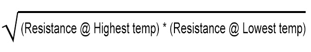
I knew that my target range was 20-40℃, but when I tried to find the data sheet for the cheap 10k thermistors I had in the parts bin, I discovered that Electrodragon provided only three temp/resistance pairs [ -40℃ /190.5kΩ, 12℃ /18.1kΩ, 65℃ /2.507 kΩ ] and an unusually low beta value of 3435, which did not seem to agree with the part number.
Fortunately for me the people at Stanford Research Systems Inc produced an online calculator that only needs three temperature resistance pairs to generate a set of Steinhart constants:

The calculated coefficient of 3880 convinced me that the website had a typo, and that these were probably just standard 3950 NTC’s. With that beta value I could find the resistance values that bracketed my range with the NTC Resistance Calculator over at Electro Tech:

Using the geometric mean method with those two temps suggests that my optimum series resistor would be 8179 ohms. Plugging that and the pro-mini’s 3.3v rail voltage into the next calculator provides your divider outputs:

So the delta between those two targets is 1.03 volts, or 31% of the pro mini’s default ADC’s range. That’s an improvement over the 10k ballast, however 0.09°C/LSB still isn’t enough write a blog post about it.

This is the general case equation which lets you calculate the needed bias resistor value using any arbitrary Vcc & aref combination. (provided Vcc is constant) NOTE: the AREF pin has its own internal resistance of ~32k Take this into account if you want to create an arbitrary Aref voltage with a voltage divider as this internal resistance will be parallel to one of the divider resistors giving you an unexpected voltage. Also keep in mind that you have to run an analogRead() instruction before the AREF pin is connected.
But in that same StackExchange post user jippie explained that if you power the thermistor bridge from the rails, but set aref to the internal 1.1v band gap, (with analogReference(INTERNAL); ) you can use significantly more of your ADC’s range. Putting the thermistor on the high side (see Vout2 in the diagrams above) means the divider voltage rises with temperature, and it reaches the 1.1 aref when the ballast value is 1/2 of my lowest target resistance; which in this case is 4348Ω at 45°C. That’s would mean a serial resistor of 2174 ohms, or the nearest standard 1% value of 2k2 unless I wanted to go hunting for a perfect match with IN30TD’s non-standard resistor calculator.
Checking those endpoints again with the ElectroTech Calculator:
| 15C (T min) | 45 C (T max) |
| 15837 Ohms | 4348 Ohms |
| Vout2:= 0.4 V | Vout2:= 1.1 V ( max ) |
So the delta is now only 0.63 volts, but after the aref reset this represents 57% of the ADC’s total range. On the back of the envelope that’s 1024*.57 = 583 bits spread over 30 degrees = 19.4 bits/°C ≈ 0.05°C/LSB. At the beginning of the post, I mentioned that most of the 12 bit IC sensors offer a resolution of 0.0625°C/LSB and now we have comparable resolution with the Arduinos 10-bit ADC, and a couple of penny-parts.
In fact I don’t reach 0.0625°C/LSB till the temp falls below ten degrees:
 The trade-off here is that we are far from the ‘optimum linearity’ point, so the true resolution of the measurements changes significantly as the temperature falls, which probably causes a heap of trouble for some types of analysis. I am also throwing everything below 0°C under the bus, but since my loggers are going to be deployed under water, anything below freezing will cost me more than just temperature data…
I set up a quick test of this configuration with a MS5803 to provide a reference line for comparison:

Y axis=°C temp. Most of the jitter in the thermistor line is an artifact of the S-H calculation.
Yikes! I didn’t realize that thermistors can have significant self heating problems when you use small series resistors. Electro Tech have a handy plotter that shows how much power you are dissipating (in mWatts) through your thermistor at the different temperatures.

A typical dissipation constant for a small glass bead thermistor is ~1.5 mW/°C and some ceramics go up to 7 mW/°C. With a consistent 1°C positive offset, I was probably driving too much current through my thermistor. But when I tried switching up to a 100k NTC /22k series combination, they all gave me consistent under-reading problems. It seems that Arduino’s ADC has trouble filling it’s sample & hold capacitors if you connect inputs with more than 10K impedance, and I was more than twice that. (…though in all fairness I should also admit that I was also pushing the prescalars around…)
Self heating is somewhat less of a problem if you can cut power to your thermistors when you are not reading them, and I will need do some experiments there. I’d also like to speed up the ADC: keeping mcu up time to a minimum, and that makes me want lower input resistances. Interestingly there are some sensor applications that take advantage of thermistor self-heating for air/water flow detection.
 So choosing my series resistor ends up being a balance between different factors: Self heating, impedance, and in this case, keeping the divider output below the 1.1v Aref with a 2/1 ratio. I eventually settled on using a 40k series resistor as a pullup, with the thermistor (hopefully) keeping the input impedance low enough to prevent under reads. Flipping the arrangement meant that now the voltage divider would hit the ADC’s 1.1v maximum when the temperature fell below 10°C. At that point I will have to fall back on the crude temperature record from the RTC.
Using the the internal 1.1v means that the ADC relies on the stability of the 328’s bandgap, which often gets panned in the forums. But it seemed to have reasonably good thermal stability in the 20-45C range I’m after (Figs 31-34 pg 335) and I’m curious how bad that really is compared to something like the LM4040 if you didn’t also shell out for expensive high stability 0.1% resistors to go with it.
 Routine maintenance:
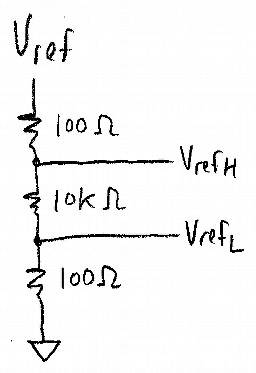
Most thermistors are only guaranteed to be within ±0.2°C absolute accuracy over a limited temperature range. While I don’t expect that much from these thermistors, I do care about the consistency of the readings over time. Jason Sachs over at the Embedded blog describes how a simple three resistor bridge can monitor your ADC’s Offset and Gain. With 1% tolerance resistors you can auto calibrate to ±0.02% of fullscale and heck, who uses A6 & A7 anyway. Right?
Then it’s a matter of:
Gain = ( ideal VrefH – ideal VrefL ) / ( ADC Measured VrefH – ADC Measured VrefL )
Offset = ideal VrefL – ( Gain * ADC Measured VrefL )
Corrected ADC reading = (Gain * raw ADC reading) + Offset
Unfortunately, I don’t have direct access to the internal 1.1 Vref, so I can only use this technique with the external 3.3v, and then find some way to convert the readings?
Riding the rails:
With the thermistor between the rails & the ADC using the internal ref, the difference between those two is important, especially if Vcc changes but the bandgap does not. Retrolefty & Coding Badly worked out an elegant bandgap based method to monitor the line voltage so that you can compensate for variations. (especially in battery powered systems) If you don’t want to use their capacitor method to pin down your chips internal vref, the folks at OpenEnergyMonitor produced a utility called CalVref.ino that calculates the bandgap voltage by comparing it to DVM readings. As this needs to be done when the logger is powered by a computers wandering USB line voltage, it is probably a bit less accurate than the capacitor method.
Both seemed to work well enough for me, though they did not always produce the same number(?) Fortunately, I just want to know the relationship between main regulators output and the internal bandgap voltage, so the ‘true value’ is not critical and I can just insert 1100mv in the RL/CB code. The resulting Vcc gives me a conversion factor (BandgapVcc / 1.1v) which allows me to adjust the 3.3v reference bridge readings to their post 1.1v changeover equivalents. Then I can use a modified offset value to correct the thermistor readings after my 1.1v changeover:
Actual ADC w 1.1aref = (Gain * raw ADC read) + [(Offset@3.3v) * (BandgapVcc / 1.1v)]
With TL431’s being so cheap, it would be reasonable to ask why not use them as a reference instead? Their 1mA minimum current is a bit of a problem for data logging applications, and the dynamic stability that they were designed for prevents you from trying certain oversampling techniques. (… more on that later …)
After many run tests, my experience of this reference ladder approach is that it gives you good gain correction, but at first it seemed to be somewhat less reliable providing ADC offsets. Even after getting the series resistors sorted out, it still took a batch of process of elimination trials before I realized that with cheap thermistors the majority of the offset is due to variation between the sensors. In my case this effect was several times larger than errors from the ADC offset, and you can only figure out what the individual thermistor’s offset value is by calibrating against a known reference…and even then it’s probably not linear… Of course if you buy interchangeable thermistors with closer tolerances, you quickly reach the price of high resolution IC sensors.
And the result:
Once you’ve plowed through all that you can convert your corrected ADC readings into temperatures using the Steinhart-Hart Formula. It requires the preliminary step of calculating the resistance of your thermistor, and there is a brilliant explanation of that over at ArduinoDIY, which ends with:
Rntc = Rseries * ((ADCmax/ADCreading)–1) // with Rseries connected to ground
Rntc = Rseries / ((ADCmax/ADCreading)–1) // w Rseries in pull-up configuration
And then you pop the calculated resistance value into one of the many code examples out there like the one in Adafruit’s thermistor tutorial though I prefer to do all that later in a spreadsheet to save memory & power on my loggers. (Not to mention the calculation errors that I usually make on the Arduino…)
I did a test including a 24-bit MS5803, a 12-bit MCP9808 and the thermistor so I could compare the output:
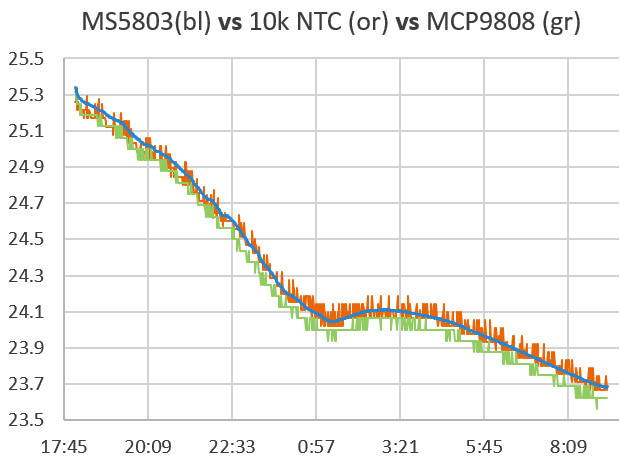 Thermistors are really twitchy due to their low thermal mass, so I did this test inside of a large ceramic pot with a lid to smooth out the changes. At first bounce I though that jitter on the thermistor line was due to poor resolution, but it turned out to be an artifact of the calculations I was doing in Excel.
When I compared the raw output of the Arduino ADC and the 9808:
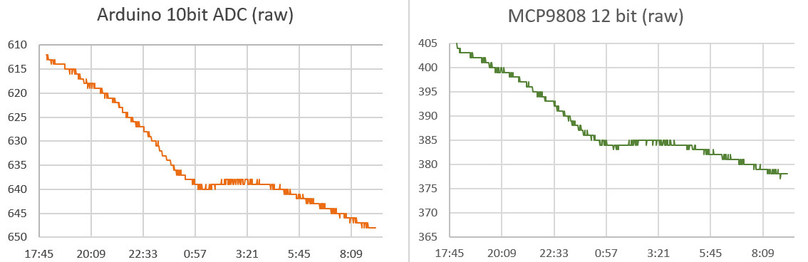
Though the left axis is inverted for the thermistor, the scale on both is the same showing that the effective resolution is better than the 12-bit sensor. (click the image for a larger version)
So perhaps correcting the initial 3.3v VrefL offset reading with that Vcc ratio was not such a good idea, and I should avoid mixing different resolutions by taking a post 1.1v read of VrefL for offset correction. Even if that is the case, tracking the positive rail still seems like a good idea for a data logger, so I will add it to the once per day events that get triggered by the 24 hour rollover.
So the job’s done with four resistors and bog standard 10K NTC right?
Uh uhh… In fact this is just the stuff I had to get a grip on before starting my quest for the ADC holy grail. I didn’t want something as good as the 12-bit sensors, I wanted something better, and the semi-mythical technique of oversampling promised to deliver all the resolution I could ever want from a humble Arduino… in theory…
But this post is already miles too long, so for now I will just leave you with a teaser from a recent run-test showing output from an 24-bit MS5803 vs a 256 sample average using the Arduino ADC and that same 10k NTC thermistor:

Y axis=temp in °C Note: I have offset the curves here for easier visual comparison. The resolvable feature size is already well below 0.01°C and I am sure that I can push that a bit farther…
You have to throw in another resistor, and a couple of capacitors, and I still have some niggling details to work out optimizing the technique to use the least amount of power. When I get all that sorted, I will post the gritty details…
Addendum 2016-06-23:
There is a thermistor based Compost Sensor project by kinasmith at Instructables which uses wireless Moteinos and a cellular module to relay the data. Cool stuff. Also there is a discussion of the lookup table method to address the accuracy of your thermistor readings (which I did not really talk about in this post) over at Mike’s Lab Notes.
Addendum 2016-08-01:
In this blog post, Ejo puts an ADS1115 / thermistor combination through its paces, using a combination of single and differential readings to remove voltage bias. His resolution reached 0.00427°C And here is another group combining the ADS1115 with a bridge.
Addendum 2017-02-27:
Well it took a lot longer than I expected, but I finally got the post on How to do Oversampling with an Arduino out the door. The pin toggling method I’ve come up with is pretty darned easy, and gives you access to at least 4-5 more bits of ADC resolution.
Addendum 2017-04-26:
I’ve moved on to calibrating the thermistors, and in the process I learned that it’s probably not a good idea to combine the 1.1v aref, with the oversampling method. But I did it anyway.
Addendum 2017-09-26:
You could get another bit of hardware resolution with a two element varying bridge and then doing a Pseudo-Differential reading with the Arduino ADC. I still haven’t wrapped my head around the math for that yet, which would get tricky if you were simultaneously using 1.1v aref – since your bridge could not be symmetrical.
Addendum 2019-03-25:
I’ve been developing a new method for reading thermistors with the Input Capture Unit on pin D8. Micro-controllers count time much more precisely than ADC’s measure voltage, so this new approach delivers more resolution than 16-bit oversampling in about 1/10th the time & power.

Awesome! So much useful information in one page!
Two questions:
– Could you make the 100k NTC / 22k series combination work if a capacitor is placed between the junction and ground?
– Could you feed the NTC/R and the analog calibrator from a GPIO so you do not have the self-heating and power consumption problems?
Thanks for a very informative blog.
Edésio
1) Yes, I am pretty sure a small ceramic capacitor would solve the under-reading problem if you had a system that was powered long enough for the capacitor to settle at the divider voltage. This takes longer with larger value resistors if you remove power from the bridge when the thermistor is not being read.
2) I think you could power the Thermistor bridge with a digital pin, depending on the final accuracy you are after, and the resistances of your NTC and series resistor. There is about 40 ohms of internal resistance on a digital pin, so with small value thermistor/resistor combinations (like I was using earlier) this causes a voltage drop at the pin that changes with temperature if you are using the pin to provide power. Up at 100k/22k this is probably negligible though.
Very interesting.
Since I didn’t expect great variation in cave temperature maybe can you increase the resolution if you use the ADC in a little range of the temperature?
You can read the post on Oversampling to see how I’ve boosted the ADC resolution. With 1024 samples I’m reaching better than 15 bit, which is delivering thermistor resolutions between 0.002 – 0.004 °C. That’s good enough for my application. I’ve also managed to calibrate those therms to better than ±0.2°C
I’m just getting into Arduino and this series of posts has really helped get an idea of what can be done. My 1st go has been to read temperatures from a thermistor which I’ve managed, but now I want to improve the accuracy. I have a daft question that looking on all your thermistor posts I can’t seem to find the answer to. I can’t seem to find out how you make the bridge circuit as the self heating simulator picture you gave has two thermistors in the circuit, is this really the case? Are you balancing one against the other?
No, the calculator at electro-tech simply displays the information that way, but it’s good to see what voltages you would get from the high side vs low side arrangements. I’m not using a bridge because the Arduino can only do single ended readings. However if you wanted to use an ADS1115, you could use a bridge. WRT accuracy, most of the parts I’m using are really cheap stuff, so there are far too many temperature coefficients in the system for a bridge arrangement to give me better accuracy. Instead I roll all the errors into the a calibration against an Si7051. You can see the details on my page about calibration.