

This in-cave micro-climate recorder had pressure & temperature sensors mounted in little wells of Loctite E30-CL epoxy. This sensor potting method is described in our OLDER build tutorials. Weather sensing stations are the most popular type of Arduino-based Sensor project on the instructables.com website.
This post isn’t another How-To tutorial for a specific sensor because the Arduino community has already produced a considerable number of resources like that. You’d be hard pressed to find any sensor in the DIY market that doesn’t give you a dozen cookbook recipes to follow after a simple Google search. In fact, you get so many results from “How to use SensorX with Arduino” that beginners are overwhelmed because few of those tutorials help people decide which type of sensor suits their skill level. This post attempts to put the range of different options you can use with a Pro Mini based data logger into a conceptual framework, with links to examples that illustrate the ideas in text.
One thing to note before you start is that many modern sensors will only accept 3.3v inputs, so UNO based projects need to check if the sensor they want to use is 5v tolerant. Most sensors from vendors like Adafruit put regulators on their breakout boards to handle this 3.3v-5v translation, but you may have to place level shifters between some of the more advanced digital sensors and an UNO based logger. Occasionally you run into the opposite situation where the sensor requires 5v (or more) forcing Pro Mini based systems to do the same thing.
Also note: Videos from Tom Igo & Jeff Feddersen’s sensor series ( Survey1&2, Datasheets & Interfacing ) make an excellent accompaniment to the material presented here.
Analog Sensors:
Some substances react to energy input by changing their physical or electrical properties. Arduinos can only read voltages, so to record these changes in the physical world some kind of circuit is needed to convert those properties into a voltage. Sensors that output continuously varying voltages in response to natural phenomenon are called analog sensors. Arduino pins A0 to A7 are analog input pins, and the ADC inside the microprocessor converts those voltages into a numerical value between 0 and 1023. It’s worth keeping in mind that those numbers are somewhat arbitrary depending on the reference voltage, and the behavior of your sensing circuit – so it’s up to you to figure out how to convert the raw ADC readings back into understandable units of the phenomenon you were trying to measure (like degrees Celsius for temperature, or m/second of wind speed, etc.)

A typical photoresistor divider from Sparkfun’s Voltage Divider Tutorial It’s worth noting that many LDRs go from 100 Ohm to over 1 MOhm. For a specific range of conditions, a common rule of thumb is: R-fixed = square root of (R-sensor min × R-sensor max)
The most common analog sensors are those that change their resistance in response to temperature (thermistors), light (photo resistors) or pressure (& it’s force / stretch / bend variants) If a sensor varies in resistance, you can turn that into a voltage by adding a series resistor to create a voltage divider circuit. The fixed resistor in the divider is usually chosen with a value near the midpoint of the sensing devices range. For example, a photoresistor might vary between 1kΩ in the light and about 10kΩ in the dark, so a suitable resistor to pair it with would be ~5kΩ. For analog sensors that change by small amounts, more sensitive Wheatstone bridge arrangements combine 2 or 4 sensors in the same circuit to expand the delta, but it’s the same basic idea: you are converting a change in resistance into a change in voltage. If your resistive sensor varies over a wide range, another common technique to increase sensitivity is to use a series string of resistors, and taking each junction to ground to change the ratio of the voltage divider dynamically.
Divider methods are referred to as ratiometric because the output voltage from the circuit is some fraction of the supply voltage determined by the resistances of the components. If the input voltage is doubled, the output voltage is doubled, so these circuits work fine on 5v UNO and on a 3.3v Pro Mini. By default the Arduino ADC takes a reading by comparing it to the same rail voltage supplying the resistive divider, and sensor nerds like me get all excited about this because it means that variation in your power supply will have little effect on the readings. You can squeeze more sensitivity per bit out of the Arduino’s humble 10-bit ADC by changing to a lower internal reference voltage. However once the Aref is different from your supply voltage, rail noise shows up on the divider output unless you squelch it out with a smoothing capacitor. (related method: Capacitance Meter )
Most analog sensors are simple devices, but there are more complicated versions providing modified analog output, where some extra circuitry has been added to convert the highly non-linear response you get from typical resistance based sensors into the kind of straight y=m(x) relationship you get from a TMP36. This greatly simplifies the math required to convert your analog voltage readings into the real-world property you were actually trying to measure. Some analog sensors (like thermocouples) generate tiny voltages, but those signals may be so small that they need to be amplified before the Arduinos ADC can read them, so these analog sensors may also be sold with supporting electronic boards to boost the output.
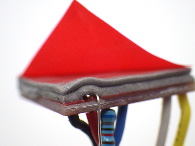
Sensors can be mounted inside a housing with a couple of layers of double sided foam mounting tape. Sensors mounted this way have stayed in place for many years of deployment. The adhesive will sag somewhat under gravity if you expose your loggers to temps >55C.
At the top of the analog sensor food chain, there are complex Micro Electro Mechanical (MEMS) devices like accelerometers. In these sensors, silicon has been machined into very tiny physical devices made from springs, coils and flat sheets. These micro-cantilevers form capacitors that react to movement by changing a voltage and they are usually arranged in sets of three on x,y,&z axes. This means you need to read three separate input pins to capture a complete reading from the device. Since the Cave Pearl data loggers use pins A4 & A5 for communications with the RTC module, and A0 to track the main battery voltage, a complex analog sensor like the ADXL335 can use up all of the remaining analog inputs on the logger unless you build it with an Arduino that makes inputs A6 & A7 available. (the Pro Mini does, the UNO does not) The limited number of analog input pins can motivate people to switch over to digital-bus sensors, though multiplexers provide another possible solution to the problem.
Using LED’s as light sensors: Some light sensors get used in conjunction with a emitter for reflectance and ranging applications. You can create a reasonably good color sensor by combining an RGB LED emitter with a simple photoresistor. And many red, yellow and green LEDs have a little known property: with reverse bias, they behave like a photo diode where the reverse current is proportional to the external light falling on them. So they can also be used to sense light because from a physics point of view, a rectifier diode, a light emitting diode and a photo-diode are basically the same device. While LEDs don’t produce the same signal strength as photodiodes designed for the job, they can be an inexpensive way to build spectrally selective detectors. LEDs detect a much narrower band of light than they emit, having a peak sensitivity at a wavelength about 50nm shorter than their peak output wavelength. Forrest Mims built some cool filterless photometers with LED sensors long before the mainstream media started waxing philosophical about ‘citizen science’. (Also see: jpiat’s Li-Fi )
If you start with the project’s basic UNO logger script , adding a new analog sensor requires only three lines of code. Add
int AnalogSensorReading = analogRead(A0);
// change A0 to match the input pin you connect the divider to
at the top of the main loop. Then add that new sensor data to the concatenated dataString which is saved to the SD card at the end of the main loop:
dataString += ", "; //comma separates new data from that already in the string
dataString = dataString + String(AnalogSensorReading);
That’s it. This simplicity is why analog sensors are usually the first ones people encounter when they are learning the ropes. Of course there are some advanced tricks you can play to supercharge Arduino’s humble 10-bit ADC, and you’ll find more useful tips over at Nick Gammon’s ADC tutorial.
Digital Sensors:
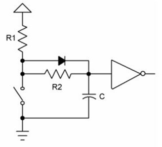
A bullet-proof de-bouncer from www.ganssle.com. Compare this to the 5-key de-bouncing circuit from the IBM 705…
Unlike analog sensors, digital sensors only output two voltages: High & Low. Usually the high voltage is the same as your power rail, and the low voltage is your system ground. In some ways that makes digital sensors easier to use, but there are some devils hiding in the details, and digital sensors cover the entire range from crude noob-level devices to Gordian knots with more computational horsepower than the Arduino itself. Even the most complicated digital sensor usually has an analog sensor hiding somewhere at its core.
I group digital sensors into three conceptual categories:
Switchers, Thumpers, & Thinkers
This is based on what kind of output they produce, rather than the complexity of their electronic circuits. And it’s not unusual for more advanced IC-based digital sensors to be as easy to use as the flippers & thumpers, because some kind soul has released a library that takes care of the gnarly low-level details.
1) Switchers
The humble push-button can be thought of as a crude pressure sensor with only two states: open or closed. Add a couple of passives for debouncing, and reed switches become the digital sensor of choice for event counting applications like the tipping-bucket rain gauges you find in weather stations. IR break-beam switches are another common implementation with on/off output.
 When you first look into digital sensors there seems to be a bewildering array of different ‘breakout boards’ and ‘sensor modules’ for the Arduino. These are often sold in bundles of twenty, thirty or even sixty different pieces. Once you get a closer look at them, you notice that many these cheap sensor modules look similar to each other:
That’s because most of those boards are simply a voltage divider connected to one leg of a five cent comparator circuit, with a trimming potentiometer setting the reference voltage on the comparators other input:

These boards switch their high/low output when the sensor circuit voltage crosses the threshold set by the trim-pot divider; and this changes the analog sensor voltage divider output into an environmentally responsive threshold alarm. It’s such a generic circuit that you could connect other resistive sensor dividers and the board wouldn’t even notice. If you use these modules with the Cave Pearl loggers, look for boards that also break out that 4th analog pin so you can also read the sensor dividers output directly with the ADC if you want to.
Integrating simple on/off digital sensors to your logger code would use almost the same pattern as the analog sensor reading:
pinMode(PinNumber, INPUT);  // Declaring the pin as an digital Input
int DigitalSensorReading = digitalRead (PinNumber);

dataString += ", ";         //comma that separates new data
dataString = dataString + String(DigitalSensorReading);

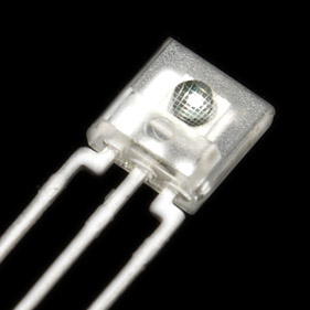
These PIR sensors are usually 5v, but you can modify them for 3.3v operation.
Those eBay boards are somewhat redundant, since the Arduino has a built-in analog comparator that can do this job with pins D6 (reference) & D7 (sensor divider) . However there are many high/low output sensors with more complex circuits that are not as easily replicated. Proximity sensors are the most common example of these more-advanced-but-still-simple category, and passive infrared (PIR) motion sensors occupy every corner of the modern world. Adafruit has a fantastic tutorial on how to use them with an Arduino, which also demonstrates how the Boolean HIGH or LOW value you get back from digitalRead() can be used with if statements to select different courses of action:
Reading = digitalRead (PinNumber);

if(Reading == HIGH)
  {   Serial.println("input is HIGH");   }

if(Reading == LOW)
  {   Serial.println("input is LOW");   }
All the I/O pins on an Arduino can be used as digital inputs (yes, including the analog lines) and the cool thing about that is the circuitry hidden behind those pins inside the microprocessor. The Schmitt trigger on each pin has read-high vs read-low threshold voltages. This lets you replicate what those cheap eBay modules do by replacing the fixed resistor in your analog voltage divider with variable one, and then connecting the output of that divider to a digital input pin. Inferring resistance (or capacitance) by timing those threshold crossovers lets you make high resolution analog readings with digital pins because micro-controllers count time far more precisely than ADC’s measure voltage.
2) Thumpers:
Switchers change state slowly by microcontroller standards, and since they can be read with a single digitalRead() command, they won’t get you much cred at the local hacker-space. To get into the digital world’s caffeine-driven middle class you have to start working with Thumpers. These are sensors which convey information by varying the percent of time the sensor outputs high at a given frequency (called pulse-width modulation or PWM) OR by changing their output frequency with a fixed 50/50 split between on&off (this is called frequency modulation or FM) .
This kind of output was common long before the Arduino existed because putting an analog sensor into the oscillator circuit feeding a 555 timer chip changes the pulses coming out the other end in proportion to the sensors resistance / capacitance / etc. You’d be hard pressed to find any environmental sensor that can’t be constructed with a couple of op-amps and a 555 (See: the conductivity sensing post for examples).
Three common methods for reading pulsed signals with an Arduino are:
- The pulseIn() Function
- External Interrupts
- Pin Change Interrupts
The output of the pulseIn() function is the time in microseconds that it took for the pin to go (or be) LOW, then go HIGH, then go LOW again. This is the method of choice for PWM thumpers, and it is extremely easy to use provided the incoming signal is a clean square wave.
Unfortunately, it does not handle frequency modulation very well at the high end, because it’s susceptible to errors in timing when detecting the start and end of very short pulses.

Note: the RCWL-1601 is the 3.3v version of this board which is code compatible with the 5v HC-SR04. The 3.3v compatible board is also sold as the HSR04-P.
Range finding sensors often output PWM signals, and the most popular of those is the HC-SR04 which is used for collision avoidance by just about every Arduino-based robot on the planet. Self-balancing robots are one of the maker movements “killer apps”, and it doesn’t hurt that the SR04 transceivers just happen to look like a pair of eyes. There’s currently a bit of a turf war between the SR04 and IR rangefinders. Ultrasonic energy is absorbed by soft materials, and SR04’s are susceptible to interference & multi-path issues in environments where there are lots of flat rigid surfaces. Infrared sensors have a much more focused beam so you get better results finding small objects…like the other robot you’re currently doing battle with. (For more precise work you can go upscale to the VL53L0X Time of Flight distance sensors, and if money is no object, you can take that all the way to LIDAR. To get the highest level range-finding merit badge of them all: MaxBotix Sonar sensors let you play the game under water…)
The SR04 is a bit odd in that it only generates one long pulse that lasts till the outbound pings return back to the sensor, but the pulseIn() implementation for the HC-SR04 could be as simple as this:
digitalWrite(triggerPin, HIGH);       // get ready to transmit the pings
delayMicroseconds(10);                // give the sensor 10 ms to settle
digitalWrite(triggerPin, LOW);        // send the out pings, wait 2ms, & set output high
duration = pulseIn(echoPin, HIGH);    // output pulse goes low when 1st return ping hits
Distance2reflectingSurface = (duration/2) / 29.1;
// Divide by 2 since 'total pulse with' = time to travels out & back = twice the distance
// Speed of sound in air = 340 meters per second or ~29 microseconds per centimeter
// Then divide the duration by 29 cm = distance in centimeters.
External interrupts handle both PWM and FM efficiently with the limitation that there are only two hardware interrupt lines on a typical Arduino. The Cave Pearl loggers are already using D2 for the RTC wakeup alarms, and that leaves only D3 available for hardware methods calling attachInterrupt().
It’s worth noting that there is also a near IR (940nm) sibling in the TSL family: the TSL245 though with IR sensors it can be tricky to extract temperature dependencies.
The TSL235R light-to-frequency sensor outputs a square wave (50% duty cycle) with a frequency proportional to light intensity. The TSL235 is self-contained, well calibrated, and very linear over the ultraviolet-to-visible light range of 320 nm to 700 nm. Calibration in manufacturing is something that most companies will try to avoid, and when you include the fact that this sensor works from 2.7-5.5v, you have a $3 sensor that’s nearly perfect for use with Arduino-based data loggers. Rob Tillaart has posted a simple bit of code that counts the interrupt pulses per second from this FM sensor over at the Arduino playground. It should be easy to integrate these functions into the Cave Pearl base code, and modify it to work with any other FM output sensor. Data from light sensors usually requires post processing with somewhat complicated luminous efficiency calculations, but if you Google around you’ll find plenty of Arduino tutorials on those steps (also see: Insolation Models).
Only D2 & D3 support external interrupt signals by default, but with a little bit of extra code interrupt signals can be received on any of the Arduinos I/O pins. Interrupts triggered from pins other than D2 & D3 are referred to as Pin Change Interrupts. Pin change interrupts are grouped into 3 ‘ports’ on the MCU. This means there are only 3 interrupt subroutines to handle input from all 20 pins. This makes the code somewhat more complicated than Rob Tillarts example, as it now needs to determine which pin triggered the ISR. That extra complication usually motivates people to use something like the PinChangeInt library for situations with a limited number of input pins.
There are many great frequency counting libraries but it’s important to note the difference between ones which count the number of pulses during a fixed “gate interval” time, and those measuring the period of a single high frequency pulse. Tillart’s code uses the counting method, and this works well for relatively high frequencies, because many cycles are counted during the gate interval and this reduces error. At lower frequencies, very few cycles are counted, and the precision suffers, so measuring the elapsed time during a single cycle is a better option:

This image is from PJRC’s FreqCount Library page, which goes into more detail on the FM sensing process. It’s worth noting some of the other useful sensor libraries that Paul Stoffregen has released including: a Onewire library for the ever popular DS18B20 temperature sensor, SerialFlash to simplify SPI memory builds, and their project blog is a font of other highly interesting things.
According to PJRC: Frequency Counting: works best for 1 kHz to 8 MHz and Period Measuring: works best for 0.1 Hz to 1 kHz. There is some wiggle room there, and you should check your sensors data sheet to make sure your method matches the output range.
If you’d rather skip the libraries, you can get closer to the bare metal with the advanced timer over-flow methods described at www.fiz-ix.com and at Nick’s Timers & Counters page. Nick’s page describes a method to measure frequency with the input capture unit on pin D8. While that’s some pretty advanced code, it allows you to measure pulsed inputs to a resolution approaching the frequency of your system clock. Some sensors like Anemometers produce output that’s so variable it can’t really be classified as either PWM or FM. Sensors like that are good candidates for using more advanced timer or interrupt based approaches.
3) Thinkers

This Grove I2C hub connects several the sensors to the bus, so only one jumper set needs to be patched down to the logger platform. The mounting shown here was done with plumbers putty, which hardens quickly, and adheres well to most plastic enclosures.
Chip-based sensors offer high resolutions and complex signal processing capabilities that can be hard to replicate on the Arduino. Most of these digital sensors send data using serial communication protocols over a common set of “bus” wires that are physically connected to all of the sensors in parallel. Serial protocols can be intimidatingly complex for beginners, but you rarely need to worry about the details because most of the vendors in the Arduino landscape release libraries to simplify the use of the sensors they sell. These libraries make it easy to work with complex sensors, and they are one of the reasons that companies like Adafruit and Sparkfun have such a dedicated following in the maker movement.
Newer versions of the Arduino IDE have a Library Manager which provides access to a large list of libraries with a one-click install. Sensors that have been used for a few years by the community often have a library available through the manager. However for new sensors, you usually have to download a library and manually place it in your
Username>Documents>Arduino>Libraries folder.
You can Learn more about installing Arduino libraries at:
Sparkfun :Installing an Arduino Library, All About Arduino Libraries at Adafruit
and Installing Additional Arduino Libraries at Arduino.cc.
Note library code can be located in several different places on your hard drive but it’s best to keep the ones you add in your sketchbook folder because the Arduino Software (IDE) upgrades itself by first erasing everything in the program root directory: including any libraries that were stored there. Libraries in your personal document folders are not deleted during the Arduino Software (IDE) update process.

Here I’ve added a resistor which pulls the CS pin high to tell this ADXL345 accelerometer to communicate with the I2C protocol rather than SPI. The value of that pull-up resistor is not critical, so they can range from a 200Ω to 10kΩ.
The digital sensor protocols you are most likely to see used with an Arduino are SPI and I2C. It’s fairly common for chip-based sensors to support BOTH protocols and for those you usually add a pull-up or pull-down resistor to the sensor module to tell the chip which method to use. SPI is preferred when fast communication is needed to move large amounts of data, but this is rarely the case for environmental monitoring. More importantly, the Arduino SD card libraries expect the SPI bus to be operating in Mode0. Adding a sensor to the Cave Pearl Logger which changes the SPI bus to one of the other three SPI operating modes would prevent data from being saved until the bus was reset to Mode0. I have yet to find an SPI bus sensor that doesn’t have an I2C equivalent.
I²C sensors are often the best choice for Cave Pearl Data Loggers.

The DS3231 RTC breakout module used on the Cave Pearl logger has a cascade port at one end, making a perfect attachment point for other I2C devices
The I²C bus or TWI (Two Wire Interface) allows a single master (the Arduino) to share communication lines with more than 100 sensor devices. (…in theory, a more realistic expectation is 5-10 sensors) Cave Pearls use a DS3231 RTC for timekeeping and the I²C breakout board carrying it provides 4.7k pullups resistors on the SDA and SCL communication lines. Each new I²C sensor gets connected to the same wires as the RTC module. If you have a good library to go with your sensor, about the only thing that might prevent it from working is a bus address conflict. Because I²C devices are all connected to the same wires, the Arduino needs a way to talk to only one device at a time and it does this by starting each message with the I²C address of each sensor. (kind of like a phone number)
The first thing to do after connecting a new I²C sensor to your Arduino, is run a bus scanner which queries every possible address to see which devices are responding. If two devices are trying to use the same address, only one of them will show up in the scan, and sometimes neither of them will. Code for this basic job for this can be found at the Arduino playground.
Running that bus scanner on a Cave Pearl data logger without any sensors are attached should produce:

This output screen tells us that the RTC breakout board is functioning and that the I²C “device addresses” are 0x57 ( this is the EEprom on that module ) and 0x68 (the DS3231 RTC). Adafruit has compiled a list of typical I2C addresses for different sensors and scanning through that list for the two we are already using on the logger finds some potential conflicts:
0x57
MB85RC I2C FRAM (0x50 – 0x57)
MAX3010x Pulse & Oximetry sensor (0x57) //(this sensor can not be used w our logger!)
0x68
This address is popular with real time clocks – almost all of them use 0x68!
AMG8833 IR Thermal Camera Breakout (0x68 or 0x69)
DS1307 RTC (0x68 only)
PCF8523 RTC (0x68 only)
DS3231 RTC (0x68 only)
MPU-9250 9-DoF IMU (0x68 or 0x69) // (must be set to 0x69 to use w our logger!)
MPU-60X0 Accel+Gyro (0x68 or 0x69)
ITG3200 Gyro (0x68 or 0x69)
Some I²C devices have only one fixed address and but most offer a small range of different addresses that you can set by connecting different pins on the module to power or to ground. This will let you resolve an address conflict, but be make sure to make corresponding changes in your code if you change a sensor address away from it’s default. Most sensor libraries will have a modifiable parameter for the device address that is used to initialize the sensor. If you have a sensor with a fixed address, you will only be able to hook up one of those sensors to the logger at a time unless you add an I2C multiplexer to resolve the address conflict.
Once you’ve confirmed the sensors show up on a scan of the I²C bus, the next steps depend on the complexity of your sensor. I²C sensors that only do one thing can often be read with a minimal amounts of code after the #include <Wire.h> statement embeds the TWI library that’s built-in to the IDE . You often see this with a basic temperature sensors like the TC74
//All I2C coms start with a handshake transaction with the device @ address
Wire.beginTransmission(address);
Wire.write(0);           //asking for register 0, the data register of the TC74
Wire.endTransmission(); // nothing is sent over the wires until wire.end is executed

//then you request the temperature data from the TC74 sensor
Wire.requestFrom(address, 1);  //this requests 1 byte from the specified address
int celsius= Wire.read();
For sensors that do more complicated things there can be many more steps, especially during sensor initialization when you might have to configure the bit-depth of the readings, the sampling speed of the sensor, and a host of other options. I’ve posted an extensive tutorial about this for tech-savvy users (see: How to configure I2C sensors ) but for beginners the best approach to adding a new I²C sensor is
1) Find a suitable tutorial by typing “How to use SensorX with Arduino” in Google or by reviewing the tutorials available at: Hookup Guides at Sparkfun, the Sensor tutorials at Adafruit, or search for code examples and links at the sensors forum.
2) Download the associated sensor library and install it into your Documents>Arduino>Libraries folder
3) Add #include <SensorLibrary.h> to the start of your code
4) Initialize the sensor in startup following the code examples for your tutorial located on GitHub
5) Read the sensor in the main loop
 Most libraries are written to provide InitializeTheSensor() and ReadTheSensor() functions that so steps 4) & 5) often end up adding only couple of lines to your code.
As a simple example look at the MCP9808 temperature sensor from Adafruit:
The Tutorial & The example code on Github
That script is quite small because the library condensed a lot of I2C handshaking down to
tempsensor.begin();  // initializes the sensor
tempsensor.readTempC();   // reads the sensor
For an example of a library driving a more complex sensor, look at the BMP180 pressure sensor from Sparkfun
Hookup guide & The example code on Github
There’s an important step at the start of the code:
#include <SFE_BMP180.h>
#include <Wire.h>
SFE_BMP180 pressure;    // creates an SFE_BMP180 object, called pressure
#define ALTITUDE 1655.0 // Altitude of SparkFun's HQ in Boulder, CO. in meters
In setup, theobjectname. appears before each call to library functions:
pressure.begin() //initializes the sensor in setup
And then in the main loop, the sensor uses a four step process to complete one reading.
status = pressure.startTemperature();
delay(time);
status = pressure.getTemperature(T);
// the temperature must be read before the pressure!

status = pressure.startPressure(3);  // with oversampling set to 3
delay(time);
status = pressure.getPressure(P,T);
Multi-step read procedures like that are quite common, because it takes time to capture high resolution readings, and in this case the temperature has to be sent as a correction factor for the pressure reading.
Then there are two more functions in the example program worth noting:
p0 = pressure.sealevel(P,ALTITUDE);
a = pressure.altitude(P,p0);
The pressure sensor returns absolute pressure, and Sparkfun have provided extra code in their library to do calculations which convert that number into sea level equivalent & altitude equivalent numbers. That Sparkfun code example is pretty typical of what you get with libraries for more complex sensors, and it should not be too hard to just open two IDE windows to copy and paste the required pieces of code from the Adafruit & Sparkfun examples into the basic Cave Pearl Logger script on Github. There is nothing magical about libraries: they are just pieces of code that you can read through yourself by opening the .cpp file listed in the same Github repository. Always review the library code if you can, as figuring out how someone else’s stuff works is an important part of learning how to program the Arduino.
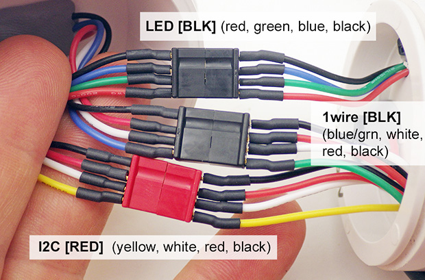
Think about your housing-logger interconnections before you start your build. My current favorite connectors are Deans Micro Plugs, which are available in 2,3,4,5,6,& 8 pin versions. Use a consistent color convention for different bus wires.
Most libraries will include a simple example sketch with the downloadable file. These show up in the IDE in the FILE>EXAMPLES> pull-down menu after the library is installed, so you don’t usually have to go all the way to Github like I did here. The included examples usually only initialize the sensor and print out some raw readings, but that’s exactly what you need to verify the sensor is working before you merge those bits into your own code.
The real benefit of a good library is not just the code, but the significant amount of time someone spent slogging through a sensors data sheet figuring out the correct sequence of operations. Just because a library exists for your sensor does not mean that it is necessarily a good one – especially when you find them out in the wild. So you should test different libraries when you have options. I generally chose libraries that require the least amount of memory at compile time, and/or ones that give me access to the ‘raw’ sensor readings in addition to the processed output. Raw sensor readings let you do calculations later in Excel to make sure the library didn’t introduce an error somewhere.
One thing that is often overlooked by library writers is supporting features that put the sensor into low-current sleep modes between readings. This is irrelevant for robots or quad-copters but it is vital for datalogger applications and is often the deciding factor for our project when choosing a library. Another thing to keep in mind is that sensor libraries don’t have to be continually upgraded like the software you run into on a more complex system. Once a sensor library is working, it will hang around for years with no updates because none are needed.
Well… this post swelled into another voluminous tome, but hopefully no one lost sight of the forest for the trees. Generally speaking you can buy each type of physical sensor in all of the data output ‘flavors’ described in this post. As an example, there are both analog (voltage) & digital (pulsed) anemometers, and the digital ones range from simple reed-switch thumpers to ones with onboard IC’s doing most of the raw signal processing to provide calibrated wind-speed numbers over an I2C bus. Don’t mistake the Analog vs Digital divide as any indication that one kind of sensor is necessarily better for the job you are doing. Same goes for my tongue-in-cheek categories for Flippers, Thumpers & Thinkers. They’re just conceptual tools to use when you are hunting through tutorials on instructables, or when you run into an intimidating wall of information like the Interfacing with Hardware page at Arduino.cc.
Although this post has been focused on capturing sensor data with a logger, you should also keep in mind that there are many different physical methods to measure the same phenomenon. Using the anemometer example, most people think of the traditional egg-cup spinners because that’s what they are used to seeing on rooftops, but heat-loss methods, and ultra sonic methods are also quite common. A Google search on ‘how to measure water level’ shows the incredible range of different sensors can be put to that simple task. When you are faced with a range of methods like that, the ‘best sensor’ for the job is the one you can actually get working, and that usually boils down to the amount of programming complexity you are comfortable with. Good libraries can level the playing field quite a bit, making complicated sensors almost as easy to add to your data logger as basic analog voltage dividers. And it never hurts to review the difference between Resolution, Precision & Accuracy before you choose a sensor.
Addendum 20171218
A few people have commented about my use of string variables in older versions of the basic logger code, and the general consensus is that the String class should be avoided because it can lead to memory fragmentation. It is better to use character arrays, but there is a significant learning curve there and strings will let you build a working data logger when you are just starting out. Majenko has one of the most concise summaries of steps to address this issue, and there is a reasonably good introduction to character arrays, and many other helpful concepts at the Starting Electronics: Arduino Programming Course (see: Section 18). Personally, I find that having to re-jig sprintf() statements when I want to add another sensor to my logger is a pain in the backside. A more memory friendly approach could be to simply open the file and then save the variables directly to the SD card without the string concatenation steps:
dataFile.open(FileName, O_WRITE | O_APPEND);
dataFile.print(AnalogSensorReading); dataFile.print(",");
dataFile.print(DigitalSensorReading); dataFile.print(",");
[...]
dataFile.close();
An alternative way to address String memory issues is to use the Pstring library by Mikal Hart. “Print-to-String” is a lightweight Print-derivative string class that renders text into a character buffer that you define at the start of your program.
char DATABuffer[30];  //This character array receives the ascii characters
// it's worth noting that you can't move more than 30 bytes at a time
// over the I2C bus due to limitations of the wire library buffer,
// so my receiving arrays are usually [30] bytes long.
The data concatenation steps I described previously for the basic UNO logger:
dataString += ", ";      //comma that separates new data
dataString = dataString + String(DigitalSensorReading);
are slightly different for the more advanced Cave Pearl logger code which uses the Pstring library:
PString str(DATABuffer, sizeof(DATABuffer));// set the array as the receiving buffer
str = "";                                   // this empties the receiving buffer
str.print(CycleTimeStamp); str.print(",");  // this data is already in ASCII format
str.print(DigitalSensorReading); str.print(",");     // this data is an integer
//add more variables as needed  up to the [30] char limit
// separating each additional sensor reading with a comma
It does not matter what what the source variable format is – float, integer, etc – it all gets rendered into ascii by the str.print statements. And Pstring will never cause a buffer overflow because any excess data that you try to add to DATABuffer is simply discarded. That receiving buffer will always contain valid (i.e. NULL-terminated) C string data. This makes the method much friendlier for people who are new to programming.
To save the sensor data stored in DATABuffer char array to the SD card use file.write:
file.open(FileName, O_WRITE | O_APPEND);
file.write(DATABuffer, sizeof(DATABuffer));
file.close();
Addendum 201907:
The latest revision of our logger starter sketch dispenses with the string manipulation described above, and just writes the variables to the SD card directly with file print statements.

Thanks for posting this. You are right about a noob being overwhelmed, there is a ton of great information out there as is evidenced by all of your links. This made me wonder where GPS sensors fell into your categories. The assumption I make is that it is in the same category for temperature sensors.
Actually GPS breakouts are an entirely different can of asynchronous serial worms, and I’ve already been thinking about a dedicated post on how to parse and log the National Marine Electronics Association (NMEA) output they produce. I didn’t bring them up here because, depending on how they’re connected to an Andruino Uno, the TTL interface could prevent you from using the GPS module at the same time as your computer is connected on a USB port. This can make debugging a long & frustrating process. GPS signals are pretty much impossible to receive in caves, so my real interest in NMEA sensors is the rare examples I’ve heard about where people hack into cheap fish finders, turning them into Arduino based sonar sensors for underwater range finding.
But getting back to GPS: the general approach of 1)Find a good tutorial 2)Download the library and 3) Open your code & the example on Github at the same time, and hand-bomb stuff from one to the other – that all still applies. And you will find excellent tutorials at Sparkfun, & Adafruit to help you work through the variety of GPS sensors out there.
For the record, my pet name for GPS sensors (and others that send ascii data) is “Stringers”
Great post! Sensors need a tome but your post is a great concise start for a beginner.
Just two addenda (or addendums?).
There is another class of analog sensor that instead of generating a voltage they control the current that go across them: the current loop sensors. Most of them uses the 4-20mA interval, it is a standard, so if you get a current outside this interval you know that there is a problem. They are very good in noisy environments or if you use long wires. I know that caves usually are noise free so this is outside your main interest.
There are four ways to read pulsed signals. The fourth is a counter that uses the signal as clock and you get the time at the beginning and at overflow interrupt. If you have high frequency signals this is better that the Tillaart approach because the counting is done in hardware and is faster that the IRQ approach, you can read higher frequencies. But if you have low frequency signal this approach is not very good.
There’s a good video from AvE explaining how to use current loop sensors with an Arduino.
These sensors are fairly rare in Arduino-land because most of them expect an industry-standard loop power supply of 18 to 24 volts, and this is significantly higher than the Arduino rail, especially when you are running a 3.3v Promini system. So you have to add support circuits for that (which is a pain if you want everything in a small remotely deploy-able package like a datalogger) This also tends to move current-loop sensors away from hobbyist friendly price points. It’s also less common for DIY’ers to need sensor wiring runs in the 300m+ range: Most projects do fine with runs in the 30-60 m range you get from with one-wire sensors (See: Developing a DS18b20 sensor chain) and I’ve had good success with I2C sensors on 20m cables.
Over at the Arduino.cc forum retrolefty also mentions another issue for DIYers:
“If the current loop is ever opened, by mistake or error is some ways, that the total loop source voltage (24v in this example) can be applied to the Arduino input pin, so some form of voltage or current limiting is required to protect the Arduino.”
This is usually 5v1 zenner diode from the input of the Arduino to ground with a 10K limit resistor to protect the the diode and the input.
Anyway, for beginners who find theres a current loop sensor they absolutely have to use:
Cooking hacks has an UNO shield with a reasonable tutorial walk-through:
NCD has a rig using an ADS1115 and INA196
And theres an ads1115 based Nano shield on Tindie. The CN0336 looks like it might also be usable with Arduino projects.
I did link the overflow pulse counting method at http://www.fiz-ix.com/2012/11/measuring-signal-frequency-with-arduino/ but I figured that would be a bit intimidating for people building the Cave Pearl loggers as one of their first real Arduino projects. But I do think it’s the coolest method of the lot, and it works reasonably well with non-square-wave signals.