
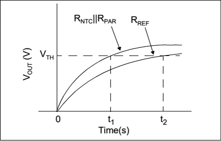
AN685 figure 8: The RC rise-time response of the circuit allows microcontroller timers to be used to determine the relative resistance of the NTC element.
For more than a year we’ve been oversampling the Arduino’s humble ADC to get >16bit ambient temperature readings from a 20¢ thermistor. That pin-toggling method is simple and delivers solid results, but it requires the main CPU to stay awake long enough to capture multiple readings for the decimation step. (~200 miliseconds @ 250 kHz ADC clock) While that only burns 100 mAs per day with a typical 15 minute sample interval, a read through Thermistors in Single Supply Temperature Sensing Circuits hinted that I could ditch the ADC and read those sensors with a pin-interrupt method that would let me sleep the cpu during the process. An additional benefit is that the sensors would draw no power unless they were actively being read.
Given how easy it is drop a trend-line on your data, I’ve never understood why engineers dislike non-linear sensors so much. If you leave out the linearizing resistor you end up with this simple relationship.
The resolution of time based methods depends on the speed of the clock, and Timer1 can be set with a prescalar = 1; ticking in step with the 8 mHz oscillator on our Pro Mini based data loggers. The input capture unit can save Timer1’s counter value as soon as the voltage on pin D8 passes a high/low threshold. This under appreciated feature of the 328p is more precise than typical interrupt handling, and people often use it to measure the time between rising edges of two inputs to determine the pulse width/frequency of incoming signals.
You are not limited to one sensor here – you can line them up like ducks on as many driver pins as you have available. As long as they share that common connection you just read each one sequentially with the other pins in input mode. Since they are all being compared to the same reference resistor, you’ll see better cohort consistency than you would by using multiple series resistors. At 8Mhz & 3.3v you get an ICU count of about 3500 for the 10k reference resistor.
Using 328p timers is described in detail at Nick Gammons Timers & Counters page, and I realized that I could tweak the method from ‘Timing an interval using the input capture unit’ (Reply #12) so that it recorded only the initial rise of an RC circuit. This is essentially the same idea as his capacitance measuring method except that I’m using D8’s external pin change threshold at 0.66*Vcc rather than a level set through the comparator. That’s almost the same as one RC time constant (63%) but the actual level doesn’t matter so long as it’s consistent between the two consecutive reference & sensor readings. It’s also worth noting here that the method doesn’t require an ICU peripheral – any pin that supports a rising/ falling interrupt can be used. (see addendum for details) It’s just that the ICU makes the method more precise which is important with small capacitor values. (Note that AVRs have a Schmitt triggers on the digital GPIO pins. This is not necessarily true for other digital chips. For pins without a Schmitt trigger, this method may not give consistent results)
Using Nicks code as my guide, here is how I setup the Timer1 with ICU:
#include <avr/sleep.h> // to sleep the processor
#include <avr/power.h> // for peripherals shutdown
#include <LowPower.h> // https://github.com/rocketscream/Low-Power
float referencePullupResistance=10351.6; // a 1% metfilm measured with a DVM
volatile boolean triggered;
volatile unsigned long overflowCount;
volatile unsigned long finishTime;
ISR (TIMER1_OVF_vect) { // triggers when T1 overflows: every 65536 system clock ticks
overflowCount++;
}
ISR (TIMER1_CAPT_vect) { // transfers Timer1 when D8 reaches the threshold
sleep_disable();
unsigned int timer1CounterValue = ICR1; // Input Capture register (datasheet p117)
unsigned long overflowCopy = overflowCount;
if ((TIFR1 & bit (TOV1)) && timer1CounterValue < 256){ // 256 is an arbitrary low value
overflowCopy++; // if “just missed” an overflow
}
if (triggered){ return; } // multiple trigger error catch
finishTime = (overflowCopy << 16) + timer1CounterValue;
triggered = true;
TIMSK1 = 0; // all 4 interrupts controlled by this register are disabled by setting zero
}
void prepareForInterrupts() {
noInterrupts ();
triggered = false; // reset for the do{ … }while(!triggered); loop
overflowCount = 0; // reset overflow counter
TCCR1A = 0; TCCR1B = 0; // reset the two (16-bit) Timer 1 registers
TCNT1 = 0; // we are not preloading the timer for match/compare
bitSet(TCCR1B,CS10); // set prescaler to 1x system clock (F_CPU)
bitSet(TCCR1B,ICES1); // Input Capture Edge Select ICES1: =1 for rising edge
// or use bitClear(TCCR1B,ICES1); to record falling edge
// Clearing Timer/Counter Interrupt Flag Register bits by writing 1
bitSet(TIFR1,ICF1); // Input Capture Flag 1
bitSet(TIFR1,TOV1); // Timer/Counter Overflow Flag
bitSet(TIMSK1,TOIE1); // interrupt on Timer 1 overflow
bitSet(TIMSK1,ICIE1); // Enable input capture unit
interrupts ();
}
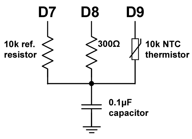
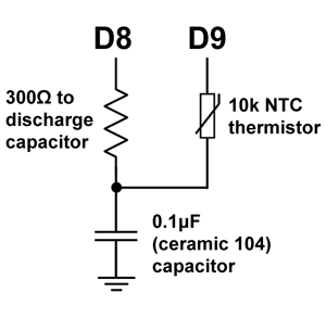
With the interrupt vectors ready, take the first reading with pins D8 & D9 in INPUT mode and D7 HIGH. This charges the capacitor through the reference resistor:
//========== read 10k reference resistor on D7 ===========
power_timer0_disable(); // otherwise Timer0 generates interrupts every 1us
pinMode(7, INPUT);digitalWrite(7,LOW); // our reference
pinMode(9, INPUT);digitalWrite(9,LOW); // the thermistor
pinMode(8,OUTPUT);digitalWrite(8,LOW); // ground & drain the cap through 300Ω
LowPower.powerDown(SLEEP_30MS, ADC_OFF, BOD_ON); //overkill: 5T is only 0.15ms
pinMode(8,INPUT);digitalWrite(8, LOW); // Now pin D8 is listening
set_sleep_mode (SLEEP_MODE_IDLE); // leaves Timer1 running
prepareForInterrupts ();
noInterrupts ();
sleep_enable();
DDRD |= (1 << DDD7); // Pin D7 to OUTPUT
PORTD |= (1 << PORTD7); // Pin D7 HIGH -> charging the cap through 10k ref
do{
interrupts ();
sleep_cpu (); //sleep until D8 reaches the threshold voltage
noInterrupts ();
}while(!triggered); //trapped here till TIMER1_CAPT_vect changes value of triggered
sleep_disable(); // redundant here but belt&suspenders right?
interrupts ();
unsigned long elapsedTimeReff=finishTime; // this is the reference reading
Now discharge and then repeat the process a second time with D7 & D8 in INPUT mode, and D9 HIGH to charge the capacitor through the thermistor:
//==========read the NTC thermistor on D9 ===========
pinMode(7, INPUT);digitalWrite(7,LOW); // our reference
pinMode(9, INPUT);digitalWrite(9,LOW); // the thermistor
pinMode(8,OUTPUT);digitalWrite(8,LOW); // ground & drain the cap through 300Ω
LowPower.powerDown(SLEEP_30MS, ADC_OFF, BOD_ON);
pinMode(8,INPUT);digitalWrite(8, LOW); // Now pin D8 is listening
set_sleep_mode (SLEEP_MODE_IDLE);
prepareForInterrupts ();
noInterrupts ();
sleep_enable();
DDRB |= (1 << DDB1); // Pin D9 to OUTPUT
PORTB |= (1 << PORTB1); // set D9 HIGH -> charging through 10k NTC thermistor
do{
interrupts ();
sleep_cpu ();
noInterrupts ();
}while(!triggered);
sleep_disable();
interrupts ();
unsigned long elapsedTimeSensor=finishTime; //this is your sensor reading
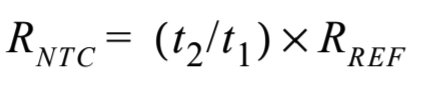
Now you can determine the resistance of the NTC thermistor via the ratio:
unsigned long resistanceof10kNTC=
(elapsedTimeSensor * (unsigned long) referencePullupResistance) / elapsedTimeReff;
pinMode(9, INPUT);digitalWrite(9,LOW);pinMode(7, INPUT);digitalWrite(7,LOW);
pinMode(8,OUTPUT);digitalWrite(8,LOW); //discharge the capacitor when you are done
The integrating capacitor does a fantastic job of smoothing the readings and getting the resistance directly eliminates 1/2 of the calculations you’d normally do with a thermistor. To figure out your constants, you need to know the resistance at three different temperatures. These should be evenly spaced and at least 10 degrees apart with the idea that your calibration covers the range you expect to use the sensor for. I usually put loggers in the refrigerator & freezer to get points with enough separation from normal room temp with the thermistor taped to the surface of a si7051. Then plug those values into the thermistor calculator provided by Stanford Research Systems.
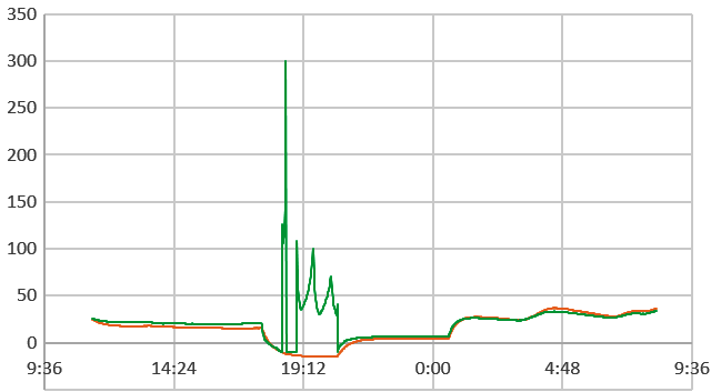
Just for comparison I ran a few head-to-head trials against my older dithering/oversampling method:
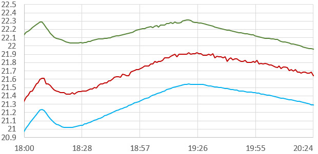
°Celcius vs time [1 minute interval] si7051 reference [0.01°C 14-bit resolution, 10.8 msec/read ] vs. Pin-toggle Oversampled 5k NTC vs. ICUtiming 10k NTC. I’ve artificially separated these curves for visual comparison, and the 5K was not in direct contact with the si7051 ±0.1 °C accuracy reference, while the 10k NTC was taped to the surface of chip – so some of the 5ks offset is an artifact. The Timer1 ratios delver better resolution than 16-bit (equivalent) oversampling in 1/10 the time.
There are a couple of things to keep in mind with this method:
si7051 reference temp (C) vs 10k NTC temp with with a ceramic 106 capacitor. If your Ulong calculations overflow at low temperatures like the graph above, switch to doing the division before the multiplication or use larger ‘long-long’ variables. Also keep in mind that the Arduino will default to 16bit calculations unless you set/cast everything to longer ints. Or you could make you life easy and save the raw elapsedTimeReff & elapsedTimeSensor values and do the calculations later in Excel. Whenever you see a sudden discontinuity where the result of a calculation suddenly takes a big jump to larger or smaller values – then you should suspect a variable type/cast error.
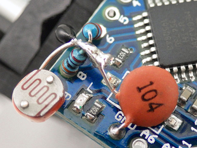
1) Because my Timer1 numbers were small with a 104 cap I did the multiplication before the division. But keep in mind that this method can easily generate values that over-run your variables during calculation. Ulong MAX is 4,294,967,295 so the elapsedTimeSensor reading must be below 429,496 or the multiplication overflows with a 10,000 ohm reference. Dividing that by our 8mHz clock gives about 50 milliseconds. The pin interrupt threshold is reached after about one rise-time constant so you can use an RC rise time calculator to figure out your capacitors upper size limit. But keep in mind that’s one RC at the maximum resistance you expect from your NTC – that’s the resistance at the coldest temperature you expect to measure as opposed to its nominal rating. (But it’s kind of a chicken&egg thing with an unknown thermistor right? See if you can find a manufacturers table of values on the web, or simply try a 0.1uF and see if it works). Once you have some constants in hand Ametherm’s Steinhart & Hart page lets you check the actual temperature at which your particular therm will reach a given resistance. Variable over-runs are easy to spot because the problems appear & then disappear whenever some temperature threshold is crossed. I tried to get around this on a few large-capacitor test runs by casting everything to float variables, but that lead to other calculation errors.
(Note: Integer arithmetic on the Arduino defaults to 16 bit & never promotes to higher bit calculations, unless you cast one of the numbers to a high-bit integer first. After casting the Arduino supports 64-bit “long long” int64_t & uint64_t integers for large number calculations but they do gobble up lots of program memory space – typically adding 1 to 3k to the compiled size. Also Arduino’s printing function can not handle 64 bit numbers, so you have to slice them into smaller pieces before using any .print functions)
2) This method works with any kind of resistive sensor, but if you have one that goes below ~200 ohms (like a photoresistor in full sunlight) then the capacitor charging could draw more power than you can safely supply from the D9 pin. In those cases add a ~300Ω resistor in series with your sensor to limit the current, and subtract that value from the output of the final calculation. At higher currents you’ll also have voltage drop across the mosfets controlling the I/O pins (~40Ω on a 3.3v Pro Mini), so make sure the calibration includes the ends of your range.
There are a host of things that might affect the readings because every component has temperature, aging, and other coefficients, but for the accuracy level I’m after many of those factors are absorbed into the S&H coefficients. Even if you pay top dollar for reference resistors it doesn’t necessarily mean they are “Low TC”. That’s why expensive resistors have a temperature compensation curve in the datasheet. What you’re talking about in quality references is usually low long-term drift @ a certain fixed temperature (normally around 20 ~ 25°C) so ‘real world’ temps up at 40°C are going to cause accelerated drift.
The ratio-metric nature of the method means it’s almost independent of value of the capacitor, so you can get away with a cheap ceramic cap even though it’s value changes dramatically with temperature. (& also with DC bias ) In my tests thermal variation of a Y5V causes a delta in the reference resistor count that’s about 1/3 the size of the delta in the NTC thermistor. Last year I also found that the main system clock was variable to the tune of about 0.05% over a 40°C range, but that shouldn’t be a problem if the reference and the sensor readings are taken immediately after one another. Ditto for variations in your supply. None of it matters unless it affects the system ‘between’ the two counts you are using to make the ratio. So the only thing to watch out for is voltage droop on your battery between readings, and we sleep the system to let the cell voltages fully restore before each channel reading.
The significant digits from your final calculation depend on the RC rise time, so switching to 100k thermistors increases the resolution, as would processors with higher clock speeds. You can shut down more peripherals with the PRR to use less power during the readings as long as you leave Timer1 running with SLEEP_MODE_IDLE. I’ve also found that cycling the capacitor through an initial charge/discharge cycle (through the 300Ω on D8) improved the consistency of the readings. That capacitor shakedown might be an artifact of the ceramics I was using but you should take every step you can to eliminating errors that might arise from the pre-existing conditions. I’ve also noticed that the read order matters, though the effect is small.
Code consistency is always important with time based calibrations no matter how stable your reference is. Using a smaller integrating capacitor makes it more likely that your calibration constants will be affected by variations in code execution time. Any software scheme is going to show some timing jitter because both interrupts and the loop are subject to being delayed by other interrupts. Noise on the rail from a bad regulator will directly affect your readings. Using a larger 1uF (105) capacitor is a safer option than a 104. This method bakes a heap of small systemic errors into those NTC calibration constants, and this approach works because most of those errors are thermal variations too. However code-dependent variations mess with the fit of the thermistor equation as they tend to be independent of temperature, so make sure the deployment uses EXACTLY the same code that you calibrated with. We are passing current through the thermistor to charge the capacitor so there will inevitably be some self heating – if your calibration constants were derived with 1-pass, then your deployment must also read only one pass. If you calibrate with a [104] ceramic & then switch to a [105] , then the temps recorded with the larger capacitor will be offset to higher than actual. Oversampling works fine to reduce noise or boost resolution, but since it leverages multiple passes that also causes more self heating.
Will this method replace our pin-toggled oversampling? Perhaps not for something as simple as a thermistor since that method has already proven itself in the real world, and I don’t really have anything better to do with A6 & A7. And oversampling still has the advantage of being simultaneously available on ALL the analog inputs, while the ICU is a limited resource. Given the high resolution that’s potentially available with the Timer1/ICU combination, I might save this method for sensors with less dynamic range. I already have some ideas there and, of course, lots more testing to do before I figure out if there are other problems related to this new method. I still haven’t determined what the long-term drift is for the Pro Mini’s oscillator, and the jitter seen in the WDT experiment taught me to be cautious about counting those chickens.
Addendum: Using the processors built in pull-up resistors
 After a few successful runs, I realized that I could use the internal pull-up resistor on D8 as my reference; bringing it down to only three components. Measuring the resistance of the internal pull-up is simply a matter of enabling it and then measuring the current that flows between that pin and ground. I ran several tests, and the Pro Mini’s the internal pullups were all close to 36,000 ohms, so my reference would become 36k + the 300Ω resistor needed on D8 to safely discharge of the capacitor between cycles. I just have to set the port manipulation differently before the central do-while loop:
A comparison of the two approaches:
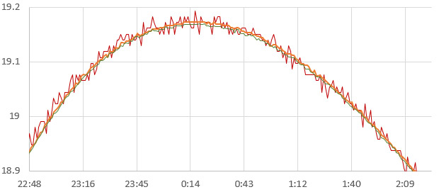
°Celcius vs time: (Post-calibration, 0.1uF X7R ceramic cap) si7051 reference [±0.01°C] vs. thermistor ICU ratio w 10k reference resistor charging the capacitor vs. the same thermistor reading calibrated using the rise time through pin D8’s internal pull-up resistor. The reported ‘resistance’ value of the NTC themistor was more than 1k different between the two methods, with the 10k met-film reference providing values closer to the rated spec. However the Steinhart-Hart equation constants from the calibration were also quite different, so the net result was indistinguishable between the two references in the room-temperatures range.
In reality, the pull-up “resistor” likely isn’t a real resistor at all, but an active device made out of transistor(s) which looks like a resistor when operated in its active region. I found the base-line temperature variance to be about 200 ohms over my 40°C calibration range. And because you are charging the capacitor through the reference and through the thermistor, the heat that generates necessarily changes those values during the process. However when you run a calibration, those factors get absorbed into the S&H coefficients provided you let the system equilibrate during the run.
As might be expected, all chip operation time affects the resistance of the internal pull-up, so the execution pattern of the code used for your calibration must exactly match your deployment code or the calibration constants will give you an offset error proportional to the variance of the internal pull-up caused by the processors run-time. Discharging the capacitor through D8, also generates some internal heating so those (~30-60ms) sleep intervals also have to be consistent. In data logging applications you can read that reference immediately after a long cool-down period of processor sleep and use the PRR to reduce self-heating while the sample is taken.
Another issue was lag because that pull-up is embedded with the rest of the chip in a lump of epoxy. This was a pretty small, with a maximum effect less than ±0.02°C/minute and I didn’t see that until temperatures fell below -5 Celsius. Still, for situations where temperature is changing quickly I’d stick with the external reference, and physically attach it to the thermistor so they stay in sync.
Addendum: What if your processor doesn’t have an Input Capture Unit?
With a 10k / 0.1uF combination, I was seeing Timer1 counts of about 5600 which is pretty close to one 63.2% R * C time constant for the pair. That combination limits you to 4 significant figures and takes about 2x 0.7msec per reading on average. Bumping the integrating capacitor up to 1uF (ceramic 105) multiplies your time by a factor of 10 – for another significant figure and an average of ~15msec per paired set readings. Alternatively, a 1uF or greater capacitor allows you to record the rise times with micros() (which counts 8x slower than timer1) and still get acceptable results. (even with the extra interrupts that leaving Timer0 running causes…) So the rise-time method could be implemented on processors that lack an input capture unit – provided that they have Schmitt triggers on the digital inputs like the AVR which registers a cmos high transition at ~0.6 * Vcc.
triggered = true;
}
pinMode(7, INPUT);digitalWrite(7,LOW); // reference resistor
pinMode(9, INPUT);digitalWrite(9,LOW); // the thermistor
pinMode(3,OUTPUT);digitalWrite(3,LOW); // ground & drain the cap through 300Ω
LowPower.powerDown(SLEEP_30MS, ADC_OFF, BOD_ON); // 5T is only 1.5ms w 10k
pinMode(3,INPUT);digitalWrite(3, LOW); // Now pin D3 is listening
triggered = false;
set_sleep_mode (SLEEP_MODE_IDLE); // leave micros timer0 running for micros()
unsigned long startTime = micros();
noInterrupts ();
attachInterrupt(1, d3isr, RISING); // using pin D3 here instead of D8
DDRD |= (1 << DDD7); // Pin D7 to OUTPUT
PORTD |= (1 << PORTD7); // Pin D7 HIGH -> charging the cap through 10k ref
sleep_enable();
do{
interrupts ();
sleep_cpu ();
noInterrupts ();
}while(!triggered);
sleep_disable();
detachInterrupt(1);
interrupts ();
unsigned long D7riseTime = micros()-startTime;
Then repeat the pattern shown earlier for the thermistor reading & calculation. I’d probably bump it up to a ceramic 106 for the micros method just for some extra wiggle room. The method doesn’t really care what value of capacitor you use, but you have to leave more time for the discharge step as the size of your capacitor increases. Note that I’m switching between relatively slow digital writes (~5 µs each) outside the timing loop, and direct port manipulation (~200 ns each) inside the timed sequences to reduce that source of error.
Addendum 20191020:
After running more tests of this technique, I’m starting to appreciate that even on regulated systems, you always have about 10-30 counts of jitter in the Timer1 counts, even with the 4x input capture filter enabled. I suspect this is due to the Shimitt triggers on the digital pins also being subject to noise/temp/etc and because other system interrupts find a way to sneak in. A smaller 104 integrating capacitor you make your readings 10x faster, but the fixed jitter error is a correspondingly larger percentage of that total reading (100nF typically sees raw counts in the 3000 range for the 10k reference). By the time you’ve over-sampled 104 capacitor readings up to a bit-depth equivalent of the single-pass readings with the 105 ceramic capacitor ( raw counts in the 60,000 range for the same 10k ref), you’ve spent about the same amount of run-time getting to that result. (Keep in mind that even with a pair of single-pass readings using the 10k/104 capacitor combination; raw counts of ~3500 yield a jitter-limited thermistor resolution of about 0.01C)
So, as a general rule of thumb, if your raw Timer1 counts are in the 20,000-60,000 range, you get beautiful smooth results no matter what you did to get there. This translates into about 2.5 – 7.5 milliseconds per read, and this seems to be a kind of ‘sweet-spot’ for ICU based timing methods because the system’s timing jitter error is insignificant at that point. With 5 significant figures in the raw data, the graphs are so smooth they make data from the si7051 reference I’m using look like a scratchy mess.
Another thing to watch out for is boards using temperature compensated oscillators for their system clock. ICU methods work better with the crappy ceramic oscillators on clone boards because their poor thermal behavior just gets rolled into the thermistors S&H constants during calibration. However better quality boards like the 8mhz Ultra from Rocket Scream have compensation circuits that kick in around 20C, which puts a weird discontinuity into the system behavior which can not be gracefully absorbed by the thermistor constants. So the net result is that you get worse results from your calibration with boards using temperature compensation on their oscillators.
The thermistor constants also neatly absorb the tempco and even offset errors in the reference resistor. So if you are calibrating a thermistor for a given logger, and it will never be removed from that machine, you can set your reference resistor in the code to some arbitrary perfect value like 10,000 ohms, and just let the calibration push any offset between the real reference and your arbitrary value into the S&H constants. This lets you standardize the code across multiple builds if you are not worried about ‘interchangeability’.
And finally, this method is working well on unregulated systems with significant battery supply variations as I test the loggers down to -15C in my freezer. In addition to battery droop, those cheap ceramic caps have wicked tempcos, so the raw readings from the reference resistor are varying dramatically during these tests, but the ‘Ratio/Relationship’ of the NTC to this reference is remaining stable over a 30-40C range, with errors in the ±0.1°C range, relative to the reference. (Note: si7051 itself has ±0.13°C, so the net is probably around ±0.25°C)
Addendum 20201011:
Re: the temperature coefficient of resistance (TCR) of your reference resistor:
“Using a thin film resistor at ±10 ppm/°C would result in a 100 ppm (0.01%) error if the ambient changes by only 10°C. If the temperature of operation is not close to the midpoint of the temperature range used to quantify the TCR at ±10 ppm/°C, it would result in a much larger error over higher temperature ranges. A foil resistor would only change 0.0002% to 0.002% over that same 10°C span, depending upon which model is used (0.2 ppm/°C to 2 ppm/°C.) And for larger temperature spans, it would be even more important to use a resistor with an inherently low TCR.”
During calibration, I usually bake the reference resistor’s tempco into the thermistor constants by simply assuming the resistor is a ‘perfect 10k ohm’ during all calculations. (this also makes the code more portable between units) However this does nothing to correct long-term drift in your reference. If you want to tackle that problem with a something like a $10 Vishay Z-foil resistor (with life stability of ± 0.005 %) then it’s probably also worth adding Plastic film capacitors which have much better thermal coefficients: Polyphenylene sulfide (PPS ±1.5%) or Polypropylene (CBB or PP ±2.5%). A quick browse around the Bay shows those are often available for less than $1 each, and the aging rate (% change/decade hour) for both of those dielectrics is listed as negligible. The trade off is that they are huge in comparison to ceramics, so you are not going to just sneak one in between the pins on your pro-mini. Be sure to check the rated voltage – and don’t order them if they are rated >100v as the common 650v film caps are too big to be practical on small logger builds. For the coup de grâce you could correct away the system clock variation by comparing it to the RTC.
Addendum 2020-03-31: Small capacitors make this method sensitive to a noisy rail
After a reasonable number of builds I have finally identified one primary cause of timing jitter with this technique: a noisy regulator. To get sleep current down I replace the stock MIC5205’s on clone ProMini boards with MCP1700’s and I noticed a few from a recent batch of loggers were producing noisy curves on my calibration runs. One of them was extreme, creating >0.5°C of variation in the record:

ICU based Thermistor readings VS si7051 reference. Sensors in physical contact with each other. Y axis = Celsius
But in the same batch, I had others thermistors with less noise than the si7051’s I was using as a reference. All were using small 104 ceramic capacitors for the integration, producing relatively low counts (~3500 clock ticks) on the 10k reference resistor.
For the unit shown above I removed the regulator, and re-ran the calibration using 2x Lithium AA batteries in series to supply the rail voltage. No other hardware was changed:
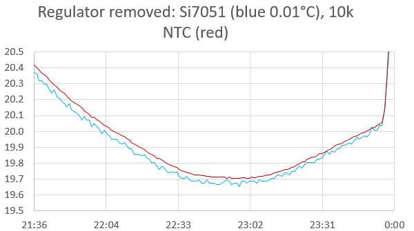
Same unit, after regulator was removed. Samples taken at 1 minute interval on both runs.
In hindsight, I should have guessed a bad regulator was going to be a problem, as few other issues can cause that much variation in the brief interval between the reference resistor & thermistor readings. Reg. noise/ripple translates instantaneously into a variation in the Schmitt trigger point on the input pin – which affects the ICU’s timer count. It’s possible that this issue could be eliminated with more smoothing so I will try a few caps across the rails on the less problematic units. (~1000µF/108 Tantalums can be found for 50¢ on eBay but I will start with a 10µF/106 & work up from there)
Addendum 2020-04-05: 106 ceramic across rails increased ICU reading noise (w bad reg)
Adding a cheap 106 (Y5V ceramic) across the rails more than doubled the noise in the readings of the NTC with this ICU technique. This is interesting, as it goes completely against what I was expecting to happen. Possibly that 10µF cap was just badly sized for this job or had some other interaction via inductance effects that actually accentuated the noise? I probably need a smaller, faster cap for the job.
Changing the sampling capacitor from a 104 (0.1µF) , to a 105 (1µF) dramatically reduced the problem. Not surprising as the rail noise from the regulator is relatively consistent, while the reference timer counts change from ~3500 with a 104 capacitor to ~60,000 with the larger 105. So the jitter is still there, but it is proportionally much smaller. I’m currently re-running the thermistor calibration with that larger capacitor. If the gods are kind, the S&H thermistor constants will be the same no matter what sampling capacitor is used.
It’s worth noting that this issue only appeared with the most recent crop of crappy eBay regulators. But if you are sourcing parts from dodgy vendors, you’d best go with a 105 sampling capacitor right from the start to smooth out that kind of noise
Addendum 2020-04-06: Re-use old S&H constants after changing the sample capacitor?
After discovering the reg. issue, I re-ran a few thermistor calibrations once the sampling capacitor had been changed from a 104 to a 105: This reveals that the thermistor constants obtained with a 104 sampling capacitor, still work, but it depends on the tolerance you are aiming for: with the older 104 cap constants drifting over a 40°C range by about ±0.3 Celsius. The extra resolution provided by the larger 105 cap is only useful if you have the accuracy to utilize it (ie: It doesn’t matter if the third decimal point is distinguishable of the whole number is wrong) I generally aim for a maximum of ±0.1°C over that range, so for our research loggers that’s a complete do-over on the calibration. From now on I will only use 105 caps (or larger) with this ICU technique on regulated systems. The battery-only units were smooth as silk with smaller 104 caps because the rail had zero noise.
Addendum 2020-05-21: Using the ADS1115 in Continuous Mode for Burst Sampling
For single resistive sensors, it’s hard to beat this ICU method for elegance & efficiency. However there’s still one sensor situation that forces me to go to an external ADC module: Differential readings on bridge sensors. In those cases I use an ADS1115 module, which can also generate interrupt alerts for other tricks like ‘event’ triggered sampling.
Addendum 2021-01-24 Don’t sleep during the do-while loop with regular I/O pins.
I’ve been noodling around with other discharge timing methods and come across something that’s relevant to using these methods on other digital pins. Here’s the schematic from the actual 328 datasheet, with a bit of highlighting added. The green path is PINx. It’s always available to the databus through the synchronizer (except for in SLEEP mode?) The purple path is PORTx. Whether or not it is connected to PINx depends on the state of DDRx (which is the yellow path.)
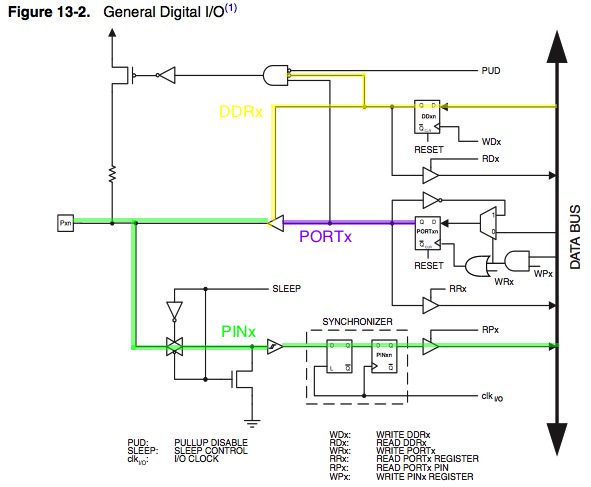
As shown in the figure of General Digital I/O, the digital input signal can be clamped to ground at the input of the Schmitt Trigger. The signal denoted SLEEP in the figure, is set by the MCU Sleep Controller in Power-down mode and Standby mode to avoid high power consumption if some input signals are left floating, or have an analog signal level close to VCC/2.
When sleeping, any GPIO that is not used an an interrupt input has its input buffer disconnected from the pin and in clamped LOW by the MOSFET.
Clearly the ICU on D8 must make it one of those ‘interrupt exceptions’ or the cap charging method would have been grounded out when entering the sleep state. If you use a similar timing method on normal digital IO pins you can’t sleep the processor in the central do-while loop.
The datasheet also warns that on pins where this is overridden, such as external interrupts, you must ensure these inputs don’t float (page 53). The implication being that when you put anything near 1/2 of the rail voltage on the input’s Schmitt trigger this will cause current to flow into or out of the pin. Yet another source of error that gets rolled into those catch-all S&H constants.
There is a good set of PORT/Pin maps for all 328p family processors at GreyGnome’s EnableInterrupt Github page.
Addendum 2022-03-09: Adding a second resistive sensor
values cannot meet your accuracy target with one thermistor.
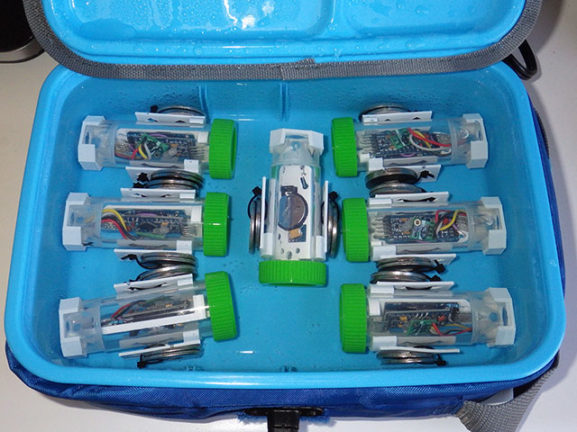
We usually integrate this ICU method with our low-power 2-part loggers as they have only a single Cr2032 as their power supply. Once the pins are pulled low these resistive sensors add nothing to the sleep current.
With the stability of battery power, a [104] is sufficient for stable ICU counts of about 3000 clock ticks for 10k ohms with an 8Mhz ProMini running at 3.3volts. Adding a second [104] ceramic capacitor parallel to the first doubles that 10k ref. to about 6000 counts. A 5528 LDR drops to about 2200 counts (with 2x 10⁴’s) in ambient room lighting, but it will go to very large resistance at night so we cap the reading at one timer overflow (65534).
For more details see: Powering a ProMini logger for one year on a coin cell.
Addendum 2024-04-20: How to calibrate NTC Thermistors
Calibrating the LDR to Lux with a BH1750 works if you have good light conditions – but that doesn’t always happen in the winter time. We have released a new post that describes how to calibrate the NTC thermistor with inexpensive DIY water baths. Also, recently found another method of reading resistance using a comparator (tip 13.3) in Microchip’s Compiled Tips ‘N Tricks Guide DS01146B

I like this method, and it makes me want to make sure I always break out D7-D8-D9 for techniques like this. I’ve been using something similar to measure the frequency of a 555-based sensor, and it seems to work well (I haven’t shut down Timer0 for that as yet; there are other things going on to worry about first).
One thing I have noticed however is setting up the code so it’s possible for the system to also time-out. That way if a wire breaks (so the pin is never pulled high) the system doesn’t lock in to a sleep state forever and ever. I’ve been doing this by keeping the processor awake and having it check to see if there’s a valid return from the timer system, -or- if a set time has elapsed. That way I can kick out of the loop even if the pin the timer is watching never changes state.
With the system sleeping, you might be able to do something similar in the overflow ISR (if the counter has rolled over some large number of times, set ‘triggered’ to true but have some way of noting that the measurement isn’t valid).
Yep, I handle that inside the ISR exactly the way you described:
if the overflow counter>some large value, set ‘triggered’ = true
It’s the simplest way to keep the system from locking up.
What resolution and accuracy are you expecting using this method?
The method is already effectively better than our standard 16-bit oversampling with the Arduino ADC but I’ve been at this game long enough to become cautious about making resolution claims because it seems like every time I figure out how to increase resolution, some “other factor” in the system becomes increasingly significant until it’s imposing some new limitations on quality of the output. But on a fundamental level – it’s a time based method, so at least the resolution is only limited by the components you use. Make the capacitor 10x bigger and you make the time 10x longer. Each order of magnitude (however you created it) adds about 3 extra bits of resolution, though at some point you start to pay too much in terms of run-time power burned for those extra bits to be worth it. And I usually see about 100-200 clock cycles of noise/variability per second from those cheap ceramic resonators on the Pro Mini, so that’s contributing ~ 0.02% error. Arduino’s clocked from a quartz crystal should do better.
Accuracy is always a matter of calibration, and so depends on your technique & the quality of your reference. Drift is also a matter of component quality: fortunately this method is not really affected by the capacitor since they never age very well. Generally I do the individual sensor calibrations with a si7051 reference, with a nominal accuracy of ± 0.1C in our sensing range. Strictly speaking your calibration reference should be about 10X better than your target accuracy, but in practice that’s too steep a price for most DIY builders.
In my experience the toughest part of the game for home builders is keeping your reference sensor at the same temperature as the sensor you are trying to calibrate. Thermal inertial makes this hard even if you have them in physical contact with each other. But if you are VERY careful to only use data from times when the system has had time to equilibrate – you can get the hysteresis low enough to bring your DIY sensor pretty close to the reference sensors accuracy -> my thermal calibration runs usually take several days to accomplish, just to get a few good plateaus of usable data. That’s a trade I’m willing to make for loggers that could be in the field for years, but that level of effort would never be ‘economically viable’. For me it costs nothing because I have to run the units for a couple of weeks just to get all the components/sensors through their ‘infant mortality’ period anyway.
I then add a second set of corrections to “normalize” a given batch of sensors if they are being deployed together as a set. This is easily generated by running the loggers together inside of a big “thermal mass” box for a few days if they are dry, or in large circulating water bath tests if they are underwater units. I salvaged a very large old chiller bath from a university lab: its controller was broken but a jury-rigged switch lets me run the chiller till some ice forms on the surface of the bath, and then I use the natural warming curve of the water as the cal data. The nice thing about that is even without using distilled water, I still get a nice big 0 degC plateau in the data set as that surface layer of ice melts.
Pingback: HIGH PRECISION ANALOG IO WITH DIGITAL PINS -Use Arduino for Projects
Pingback: High Precision Analog IO With Digital Pins
Hackaday gave us a nod for this one – generating the usual round of interesting feedback. Many pointed out factors that could affect the readings but only one of them really understood the strength of this ‘mostly’ ratiometric method:
Greg A wrote:
Many of the tempco’s in the system get rolled into the S&H constants during the calibration. And this works pretty well…but only up to a point which I haven’t bothered to characterize that well. I’m sure you could do better with a higher order poly.
This technique does depend on the consistency of the Schmidt trigger on D8. That trigger point will certainly vary over the length of a long deployment, or because of temperature, but it’s only the variation between the Vhigh trigger points on two successive readings that matters. I’ve not gone digging for that info yet, and I have a sneaky suspicion that it won’t be listed in the datasheet because it’s probably not something they cared about when they designed the chip. And possibly because jitter errors caused by coupling / crosstalk inside the chip also depend on what else you have going on inside the processor at the time.
Earlier I dismissed the capacitor variation over time because it drops out of the math, but on reflection it could affect the readings in a more round about way – even with your system regulator keeping Vcc stable: if the capacitor gets smaller over time due to aging effects you would then be passing less current through the thermistor – which would cause less self-heating than it experienced during calibration. If that’s a real concern for your deployment then I’d go with Plastic film capacitors, which have very good thermal coefficients: Polyphenylene sulfide (PPS ±1.5%) or Polypropylene (CBB or PP ±2.5%) and aging rates listed as ‘negligible’ in the datasheets (% change/decade hour).
The next most important factor is the drift of the reference resistor, which again is a matter of how picky you are on the spec. If you are serious about accuracy use 0.01% tolerance resistors, but don’t be surprised if they cost more than your thermistor.
And Timing Jitter will always be a fundamental limitation with this method. For a given Promini ceramic oscillator at 8mhz, I typically see about 75 counts raw timing jitter per second at a given temp, overlay-ed by 75-100 counts of positively correlated variation per degree Celsius. So you’ve got something like 0.03% error over a typical 40C range if you don’t correct for it. Hysteresis caused by your reference and your sensor not being in sync is usually a larger source of error.
Pingback: How to make analog sensor readings with digital I/O pins – gStore
I once did a deep dive into how my little Oregon Scientific temperature sensors work. It’s basically what you describe, but with a slight twist. Instead of doing one charge cycle, it does multiple ping-ping charge-discharge cycles (I forget, maybe 50? at ~10 usec each). The benefit would the ability to measure for longer times without using large capacitors. Also, I think it runs in pure digital input mode, using the VIL(max) and VIH(min) voltage thresholds inherent to each pin, so that the voltage just charges and discharges between those two levels. And no need to use a precious input-compare pin.
Yep, I’ve been doing 64x oversampling by reading the NTC on the rising leg, and the reference resistor on the falling leg. Just jumping between the high & low trigger points takes about 1000 timer1 clock ticks per pass – with a 10k ref & a 104 ceramic cap at 25C. I didn’t put that in the post though as I figured the code overhead would just confuse the basic message for people trying this technique for the first time.
My primary purpose with the oversampling was not to use a smaller cap or to get larger counts, but to use the decimation step to remove the 10-30 points of clock jitter I’ve seen in other ICU based techniques. I suspect that jitter would also be present on regular non-ICU pin interrupts, but it might be harder to spot without the more precise timing captured by the ICU. The technique should work on ANY I/O pin with a schmitt trigger.
Also, if you go with a ceramic 105, then your raw single-pass counts are large enough that you don’t need to bother with the oversampling because that jitter is a smaller relative source of error. You’d get the same result with a 104 cap & a 100k thermistor.