Tag Archives: DIY

Sync RTC time to a GPS & Setting the DS3231 Aging Offset Register to Reduce Clock Drift

Here the UNO supplies 5v to the (regulated 50mA) NEO6M and 3v to the RTC. The 5v UNO has no trouble responding to 3v signals from the Neo & RTC without level shifters. White wires to D11/D12 are GPS Rx&Tx via SoftwareSerial. The tantalum caps just stabilize the supply voltages which tend to be noisy on breadboards.

So far in 2024 we’ve released DIY calibration procedures for light, pressure & NTC temperature sensors that can be done without expensive reference equipment. Important techniques; but with long environmental time-series the 500 pound gorilla in the room is actually time itself. Precise timekeeping is something of a back-burner issue in the hobbyist world because so few are trying to combine data from multi-sensor arrays. And syncing to an NTP server is easy when you are already using wireless coms – provided that’s ‘good enough’ for your application. However for people who want high accuracy, using NTP is like setting your watch by constantly asking a friend what time it is.

An extension antenna is required or the GPS will never get a signal indoors. With that mounted in a skylight window the FIRST fix took over 30 minutes to acquire. Subsequent fixes took two minutes or less. It will be interesting to see how this $15 combination performs when we service loggers at heavily forested field sites.

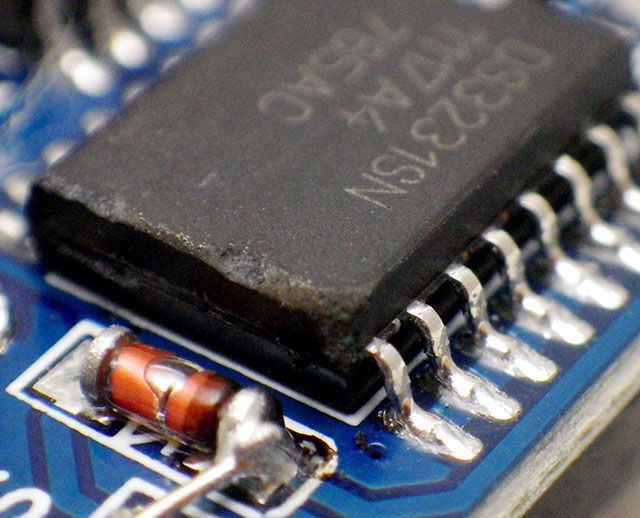
Reconstructing a sequence of events in a dynamic earth system is challenging when timestamps are generated by independent and unsynchronized clocks. But our loggers get deployed by the dozen in underwater caves, and even when you are above ground wireless isn’t really a long term option on a single Cr2032. For stand-alone operation we rely on the DS3231 RTC as they usually drift about 30 seconds per year – but there are always a few outliers in each batch that exceed the datasheet spec of about 5 seconds per month (±2ppm) for the -SN and 13 sec/m (±5ppm) for -M (MEMS) chips. These outliers are hard to spot with our usual ‘by hand’ time-setting process over the serial monitor. You can get a set of loggers within 80 milliseconds of each other with that method, but that difference is still annoyingly visible when the LEDs pip. That set me hunting for a better solution.

Paul Stofregens TimeSerial is often suggested but TimeLib.h didn’t play well with the RTC functions already in our code base. Even after sorting that out, and installing Processing to run SyncArduinoClock, I was still initiating the process. So TimeSerial didn’t get me any closer to the perfectly synchronized LEDs I was after.

This NEO-6M module doesn’t have a PPS header, but the indicator LED is driven by the time-pulse to indicate sync status. This provides one pulse per second, synced at the rising edge, for 100msec. Soldering a jumper to the limit resistor lets you to bring that signal over to the UNO with a male Dupont header pin.

SergeBre’s SynchroTime seemed like an all-in-one solution. But even after a decade working with the Arduino IDE, I still made every newbie mistake possible trying to compile that C code for windows. There are simply too many possible editor/ compiler/ plugin combinations to sift through without a lot of mistaken installations, removals & re-installs. I wasted a couple of days before realizing that code was packaged for the QT environment, and when I saw the additional cost I finally had enough. In the end, it took me less time to build my own GPS time-sync code than I spent trying to compile SynchroTime. That’s an important lesson in the difference between something that’s technically open source and a useable solution. Of course I can’t write that without wondering how many feel the same way about this project.

Jump links to the sections of this post:


Step 1: Determine the Optimum Aging Offset

Ds3231 Datasheet pg7: In the ideal case there is no better option than leaving the offset at zero. However, many chips in circulation don’t match this spec: especially the -M chips which can require offsets of (-)40 or more to match a GPS pulse at room temperature. Most of the M’s are slow, needing adjustments from (-)20 to (-)30 at room temp, while most SN’s are usually between -10 and 0, with a few SN’s running fast.

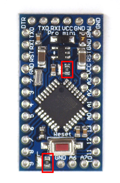
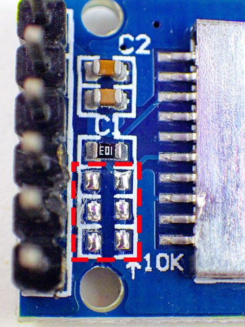
Despite those setbacks, I couldn’t give up this quest knowing that HeyPete had achieved a drift of only 26 seconds with DS3231 offline for 3 years. The key to that spectacular result was tuning the Aging Offset Register before the run. Positive values in this register add capacitance to an array, slowing the oscillator frequency while negative values remove capacitance and increase the main oscillator frequency. The change is different at different temperatures but at 25°C, one LSB adjusts by approximately 0.1ppm(SN) or 0.12ppm(M). The exact sensitivity is also affected by voltage and age so it can only be determined for a given chip empirically. The datasheets also warn not to run noisy PCB traces under the RTC that might induce capacitive/coupling effects on the crystal but many modules on the market ignore this. My ‘rule of thumb’ when servicing loggers in the field is that changing the aging register by ±3 will correct approximately 1 second of clock drift per month when I don’t have access to the resources described in this post. Of course that requires you to have good field notes so you can be sure when the logger’s clock was last set.

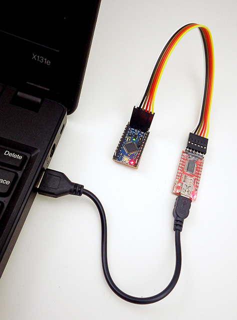
In April 2023, ShermanP proposed a method to do this using successive approximations via the Arduino system clock. After considering, and then rejecting, NTP & WWVB, he settled on GPS as the best source and then posted a ready-to-run solution on his GitHub repo: https://github.com/gbhug5a/DS3231-Aging-GPS

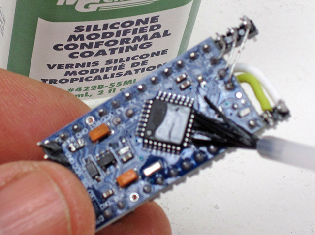
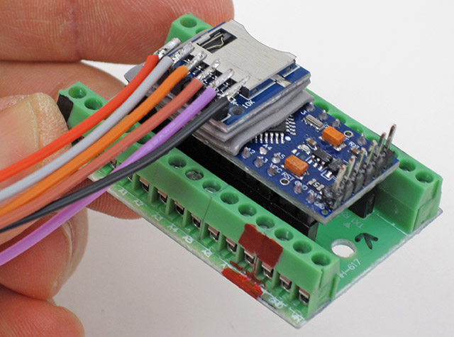
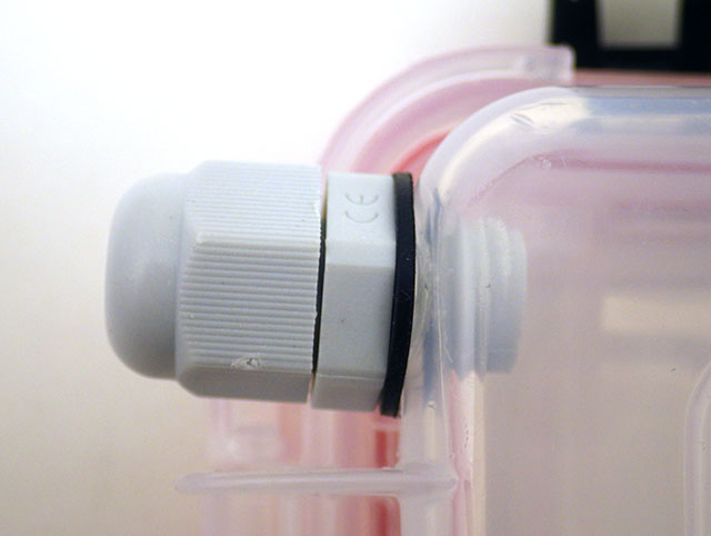
Before proceeding further, read the PDF to understand how his code works. The key idea is that “In calibrating the optimum Aging setting, you should duplicate as nearly as possible the power supply voltage the RTC will experience in its application.” although I suspect this is less critical for the crystal based -SN chips than for the MEMS oscillators. Unfortunately battery voltages change significantly with temp. so matching the rail implies you are also doing this RTC adjustment at temps near your expected deployment ranges – which may not be possible. The Cr2032s that power our loggers spend most of their operating life at 3.05v, and the power indicator LED on raw RTC modules pulls enough current that it drops the UNO’s 3.3 volt line down to about 3v. Finished loggers draw only 1-2μA while sleeping so for those I have to add a Schottky 1N5817 inline to drop that supply down to 3.05v during the test.

The rig can be used to test single RTC modules…
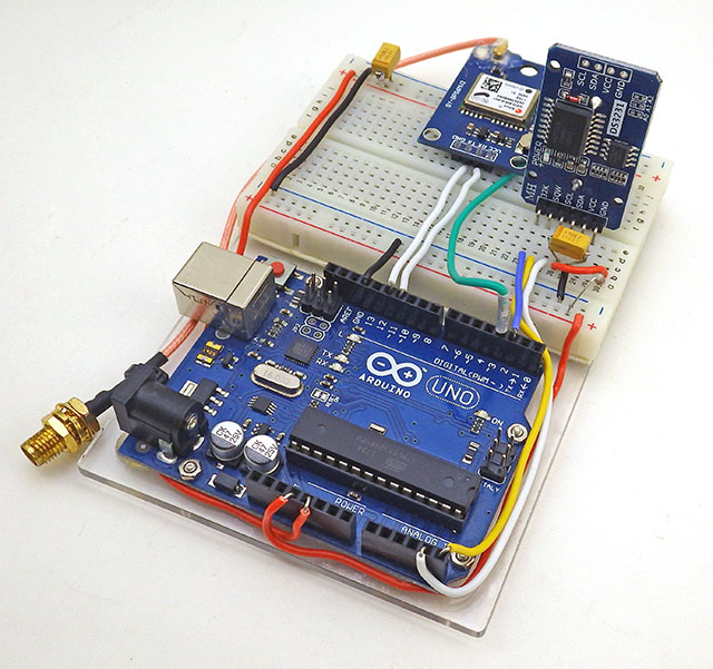
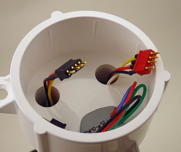
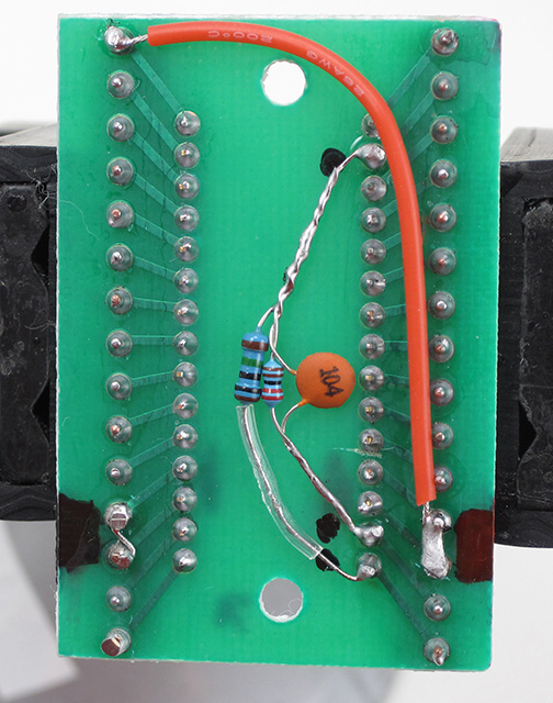
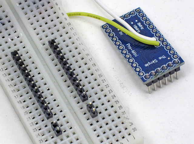
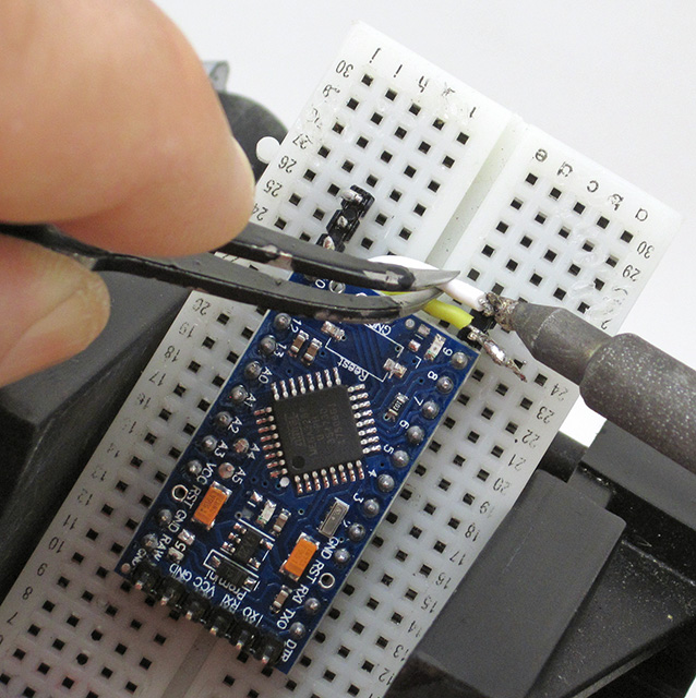
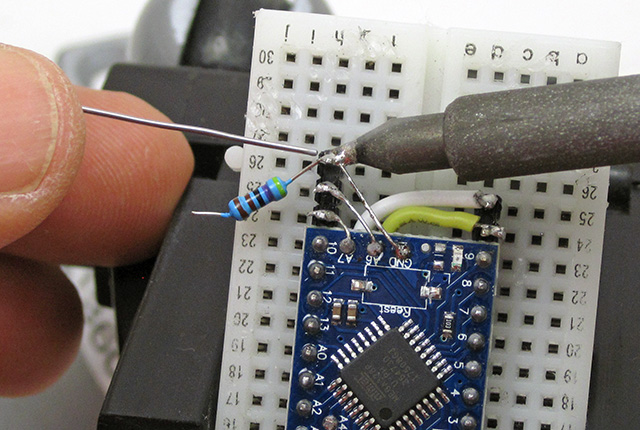
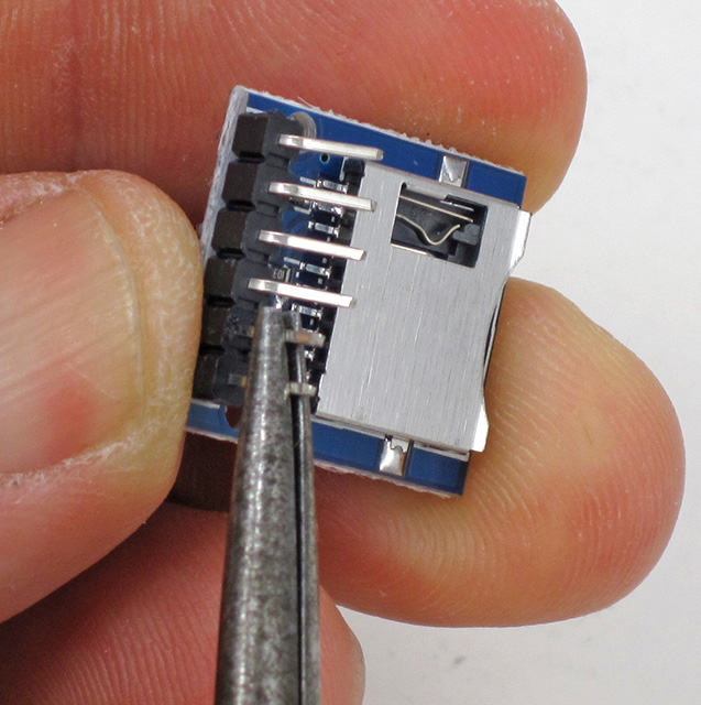
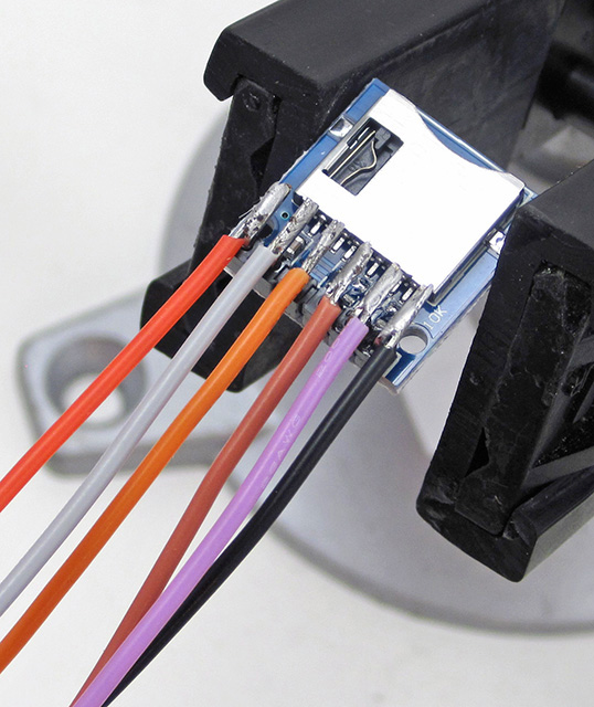
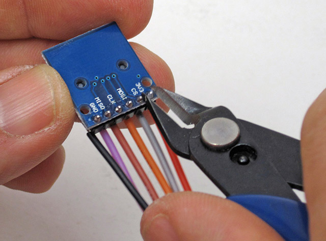
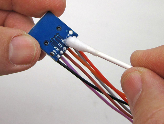
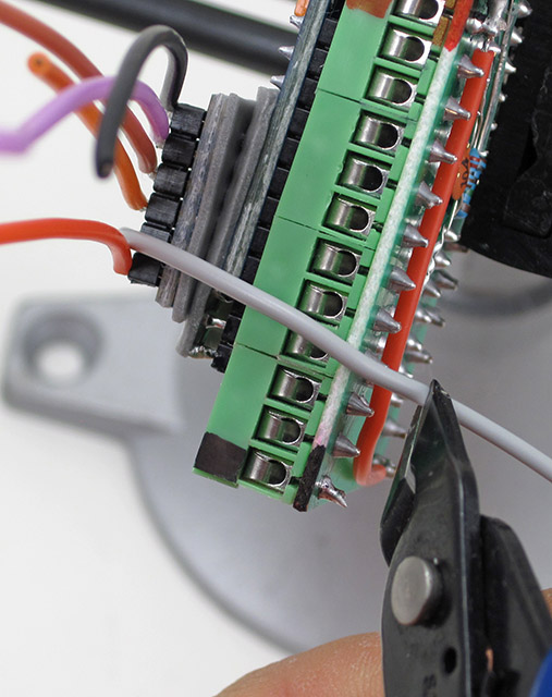
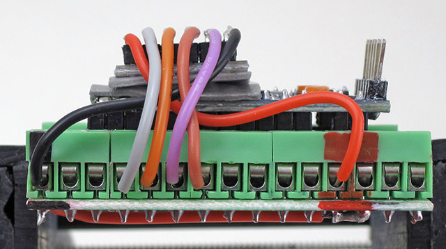
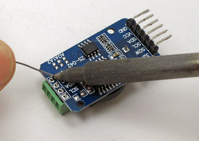
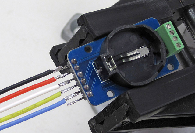
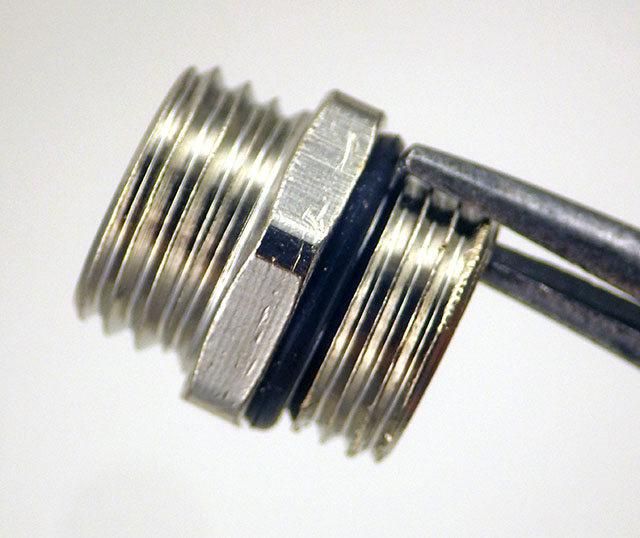
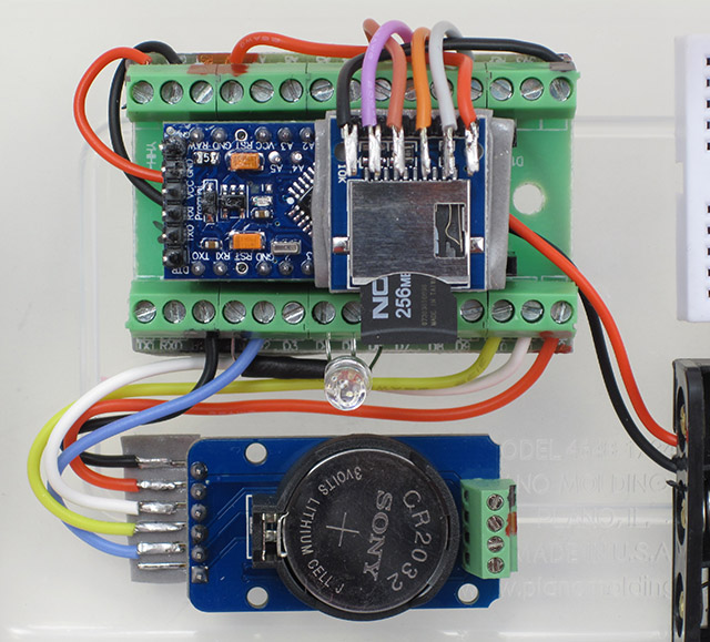
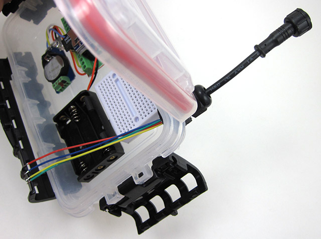
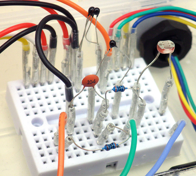
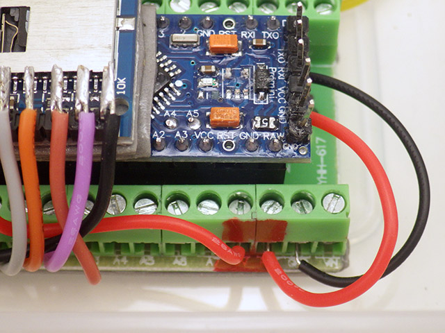
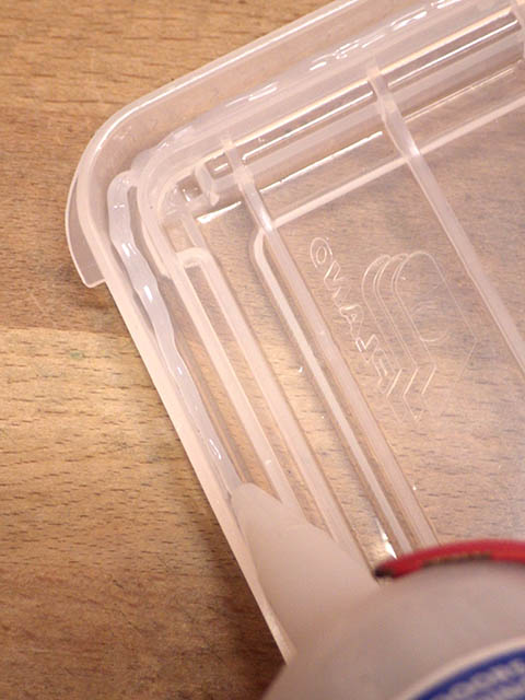
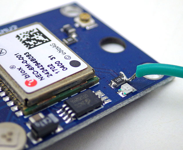
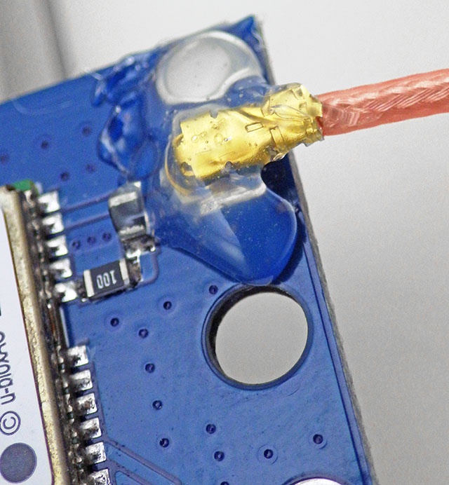
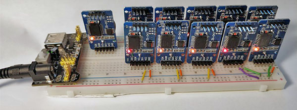
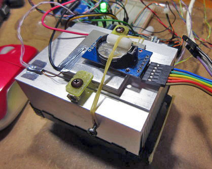
[this photo shows the GPS PPS connected to D3]
or finished loggers – provided – you put the ProMini to sleep, or load it with blink so it ignores the I2C traffic sent from the UNO. So we can do these tests & adjustments to loggers at any time after they have gone into service.

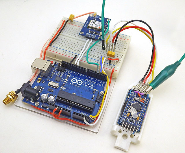
Sherman’s code uses the Interrupt Capture Unit so the PPS signal from the GPS must be connected to D8. I put a male Dupont pin on the end of the PPS tap so the UNO connection can be moved easily as the other code in this post requires that connected to D3. When testing the RTC inside assembled loggers, I have to use an alligator clip ( in green above ) for the alarm line which already has a soldered wire connection – so a female Dupont will not fit over that header pin.

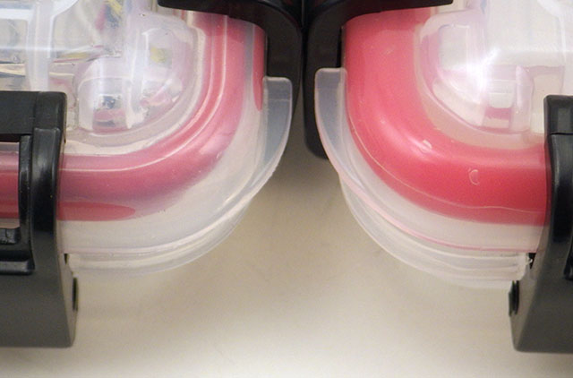
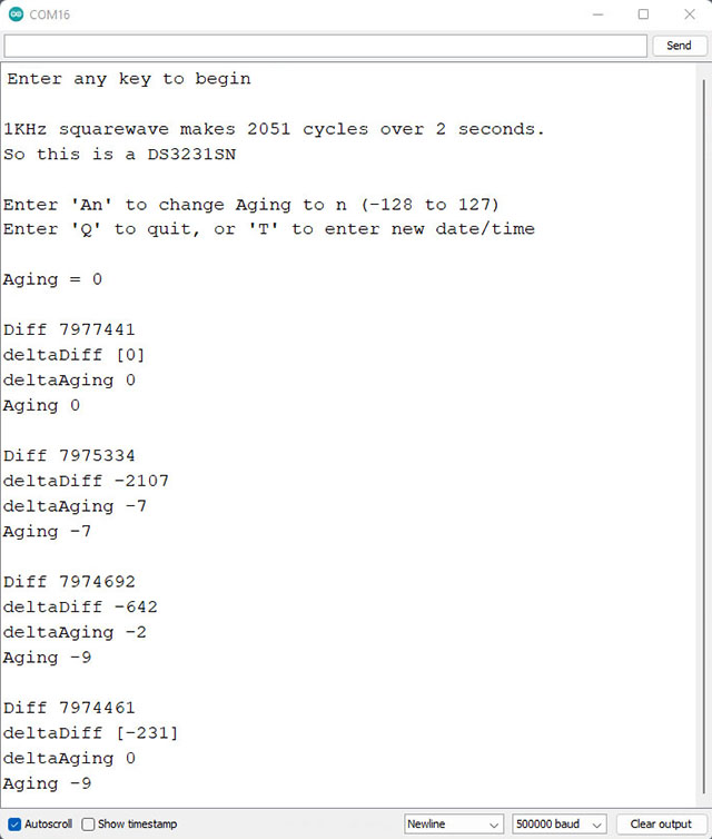
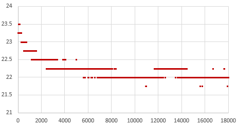
It usually takes 20-30 minutes for the adjustment on a -SN chip to reach a stable value, or settle into a pattern toggling the last bit up and down:

Each cycle of Sherman’s code shown above takes five minutes. The test tends to work better when the RTC time is close to actual GPS time, however the test changes the RTC time during the cal process. So you will need re-sync your RTC time to the GPS after the Age offset determination is run. In our version, I’ve added RTC temperature and tweaked the formatting so that it’s easier to graph the output from longer tests. But these are trivial changes.
On this (typical) -M RTC, it took an hour before the 5-minute cycles settled to a stable offset. Later runs of this unit with calcSlope() showed slightly better behavior with a value of -17 but this test might have settled there if I’d left it running longer. Averaging values from the second hour might be the best approach and you want stable temperatures so the RTC isn’t doing TCXO corrections during the test.

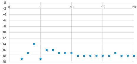
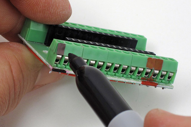
Unfortunately the DS3231 has no non volatile memory which means all registers will reset whenever the chip loses power. So I write the optimum offset from this test on the modules battery holder with a white paint marker during the component triage I do before building new loggers. About 2/3 of time I get very similar results when running this test on a completed build that I got from the RTC module by itself before the logger was assembled. However for about 1/3 of the RTCs, forcing the chip to run in low-power mode from Vbat slows down the main oscillator speed up to 2ppm – so the only safe approach is to retest the age register test after assembly. The BBSQW battery power alarm enable (bit 6 of the 0x0E register) must be set when running the RTC on Vbat.

Many have speculated that there are ‘fake’ DS3231 chips in circulation, but with so many showing scratches & scuff marks I suspect the bad chips are actually the result of rough handling during rework/recycling. And with a chip that’s been in production this long, some are bound to be decades old.

SN chips usually settle to a stable offset value within 2-3 cycles but it can take an hour or more before the -M chips produce stable age offset results. About one in 40 of the RTC modules does not settle to a consistent number no matter how long you leave it and I toss those as defective. Occasionally this is because even with the Age register pushed all the way to a max value (±127) the RTC still can not match the GPS pulse. Some of the non-calibratable units have a non functional register – you can write a value to the register and read it back but that has no effect on the output. I suspect that many of these failures are due impact damage after the chip has been dropped. I also reject any RTC where the temperature register is off by more than 3°C because they won’t be able to do the TCXO corrections. The aging register and the temperature adjustments get combined at the load capacitor bank to tweak the main oscillator, so aging register changes won’t get applied until the next (64 sec) temperature correction unless you also trigger a manual conversion. Just by chance, about one in 25 of the -SN chips keeps almost perfect time compared to the GPS with the register left at the zero default. For now I’m keeping those aside as secondary reference units.

Units per Bin VS Aging offset to match GPS pulse: 140(M) & 85(SN) RTC modules. These were selected at random from multiple eBay vendors, and tested as unmodified modules powered through Vcc at 3.05v. Six of the SN’s had zero offset and I divided those equally into the ±5 bins. Interestingly, while the SN’s are much better behaved as a group, that chip type also had the most extreme outliers with about ten either DOA/unstable or requiring extreme adjustment. I suspect crystal damage explains this observation as there was only one DOA in the batch of M chips.

To leave room for a decent range of TCXO correction, and with ±2ppm short-term wander (on the Mems chips) the aging register should only be used to compensate for about 6-7 ppm of baseline offset. I try not to use a module where the aging register correction to match the GPS is more than ±50.


Step 2: Synchronize RTC time with a Neo6M GPS

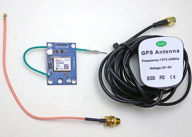
Most clock projects use NTP, but there are a few that go that extra mile and synchronize to GPS. One that caught my attention was: Super-Accurate GPS-Corrected RTC Clock – without Internet NTP He avoided the serial bus latency of those pokey 9600 baud coms by preloading variables with GPS time +1second and then waiting for the next GPS pulse before setting the RTC registers. With this concept in hand, and TinyGPS++ to parse the NMEA strings, it didn’t take long to whip up my own version for our loggers. It’s worth noting that several forums mentioned NMEA messages can exceed the 64byte buffer in SoftwareSerial so I increased this to 128 bytes by editing the file at: C:\Program Files (x86) \Arduino \hardware \arduino \avr \libraries \SoftwareSerial \src

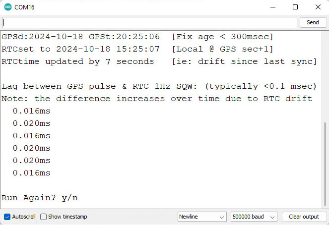
Another hidden gotcha is that GPS time can be out by 2 or 3 seconds until it receives a ‘leap seconds’ update which is sent with the Almanac every 12.5 minutes. So wait until the sync LED has been blinking for 15 minutes before setting your clock time as I don’t (yet) have an error catch for this. Our RTC time-sync code displays how much adjustment was done to the RTC time and checks the latency between the GPS pulse and the new RTC time immediately after the sync. That difference is often less than 30 microseconds, but it increases from there if you leave the system running:

Note: If you just ran the aging register test in Step1 you will need to move the PPS signal jumper from D8 to D3 before running RTC2_SyncDS3231Time2GPS The RTC alarm output stays on D2. Occasionally the process spans a transition, so if you see the RTC seconds at anything other than GPSsec+1, de-power the rtc and run it again. The RTCs internal countdown only restarts if the seconds register gets changed, so multiple runs will not reduce the lag once the time has been synced. For some reason I haven’t identified yet, the 1Hz output from -M chips often ends about 1 millisecond before the GPS pulse, producing a negative lag value after sync (because the first ‘partial’ interval is too short?)

You still have to edit the code by hand for your specific local-time adjustment but everything is well commented. Most scientists run their loggers on UTC which matches GPS default time so that local time tweak can be commented out.

The external antenna connection was pretty flakey until I secured it with hot glue.

One small issue with having to run these test utilities with the RTC at 3.05v is that you’ll need to change the battery before deploying the logger. To preserve the clock time, connect the logger to a UART so the RTC is powered continuously during any battery swaps. After the time-sync & new battery, the normal procedure is to load a logger with its deployment code which has a start menu option to set the RTCs aging offset. This gets saved into the 1k EEprom on 328p processor and once set, the base-code automatically reloads that value from the EE into the RTC’s aging register at each runtime startup. After that’s done the logger is ready to deploy – so Step 3 below is only for those who want to explore the DS3231 RTCs drift behavior in more detail.


Step 3: Testing and Verifying Clock Drift

Now that we have the aging offset, and the RTC is synced to GPS time, how do we verify what we’ve done?

HeyPete ran multi-unit drift tests on the same breadboard with all of the RTCs responding to a single I2C master. I’m tempted to try this approach to drift testing of the other sensors like the BMP280, or the BH1750 although I might need to add a TCA9548 I2C multiplexer.

One method is simply to run the clocks until the drift can be easily measured – but that can take several months. You can get immediate results by enabling the 32kHz output on a DS3231-SN and comparing that to a high accuracy source with an oscilloscope. Ideally, you calibrate to a traceable standard which is at least one decimal place better than your device resolution. Kerry Wong did this with an HP 5350B Microwave Counter and HeyPete uses a Trimble ThunderBolt Timing GPS. There are a few retired engineers out there with universal counters on the bench and for truly dedicated ‘time-nuts‘ only an atomic clock will do. But even then the times from several must be averaged to arrive at a published value, and whenever you achieve better numbers by averaging multiple measurements you obscure potential issues with jitter.

Even if we had that equipment budget, our loggers supply the DS3231 from Vbat to save runtime power which disables the 32kHz. And -M chips don’t support that temp. compensated output no matter how they are powered. So is there any validation test that can be done without expensive kit or the 32khz line?

Actually there is – thanks to the Needle Nose Pliers blog in Tokyo. He developed a method that uses least squares over one minute of aggregated readings to resolve rates of change below 0.02μs/second despite the fact that an UNO sysclock only ticks at 4μs. I wrapped his calcSlope() function with modifications needed for the UNO/NEO6 test rig used here and added an input to change the Aging register before each run. To run the drift checking code from our Github, connect the GPS PPS to D3, and RTC SQW to D2:

Note: drift in ms will increase over time and the ppm values typically vary by ±0.02 (or more for -M chips). 9.999 indicates that the code is still collecting the initial 60 readings required for slope calculation. It usually takes another minute after that for the ppm readings to settle. The 1-second cycle-count lets you know the test duration if you leave a long test running in the background.
Once the initial 60 readings are gathered, the ppm drift calculation can be done. In real world terms, ±2ppm is about 175msec of drift per day and you can see that happening in real time with this output. In the test shown above I was deliberately using an offset far from the one suggested by the Step1 test to see how much that increased the drift rate.

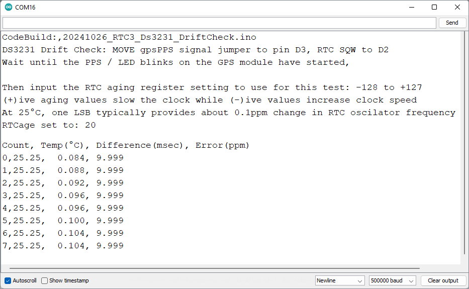
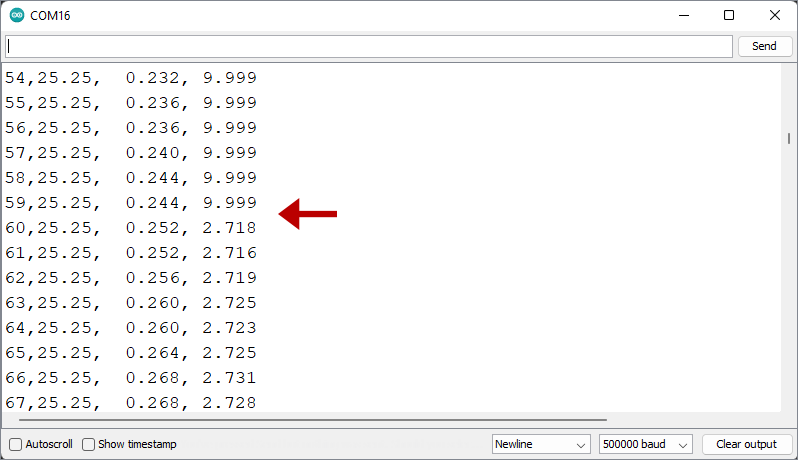
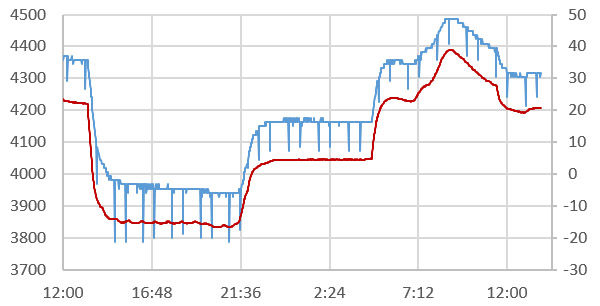
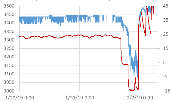
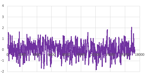
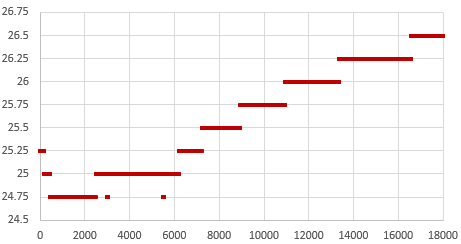
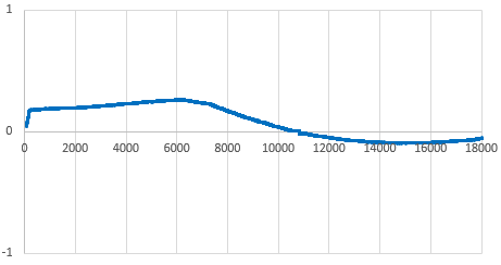
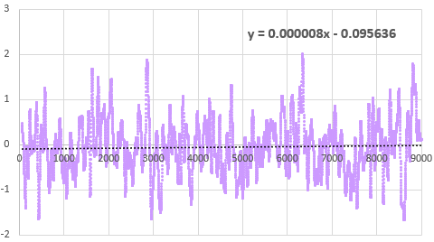
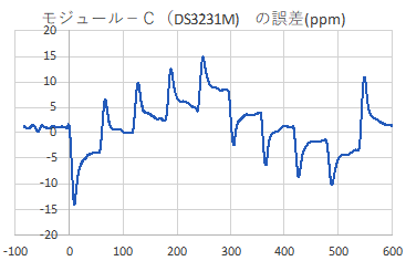
That serial output can then be copied into a spreadsheet to compare the effect that different aging offsets have on the RTC. Here are the results from two five-hour tests of a DS3231-M; first with the the Age register set at zero and then with it set to -17. The clock time was sync’d to GPS time before each test to make the graphs easier to compare with the x axis is seconds: (click to enlarge)

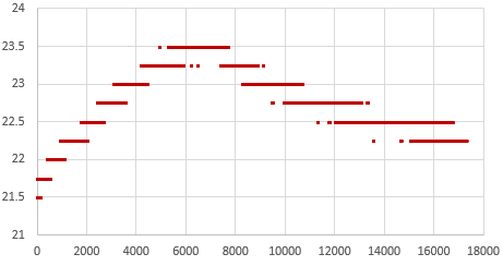
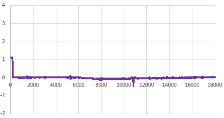
RTC temp. during test —> Msec offset from GPS —> Drift Error PPM

RTC temp during this test: 22°C
Drift: 35msec slow after 5 hours
Average error: +2ppm (with ±2ppm jitter)

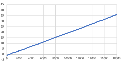
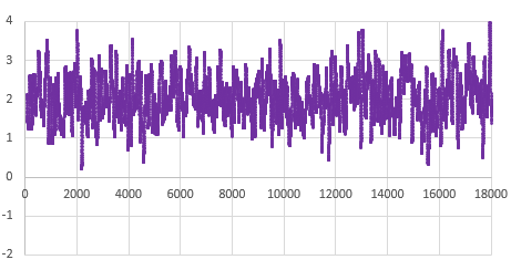
At the Age=0 default, this RTC’s 1Hz output was 35 milliseconds behind the GPS pulse after five hours, which would be roughly equivalent to 100 seconds of drift per year. The average error hovered around +2 ppm. This is well within spec for a -M chip as ±5ppm implies up to 155 seconds of drift per year.

Then the Aging register was set to -17 (as determined by the test from Step1) and the drift examination was done again. That same RTC module was now only 0.5 milliseconds behind the GPS pulse after five hours, with the slope-derived error averaging close to zero ppm:

Higher 23°C temps on 2nd test
Less than 1ms of drift in 5h
Average error: close to 0ppm (but jitter is the same ±2ppm)

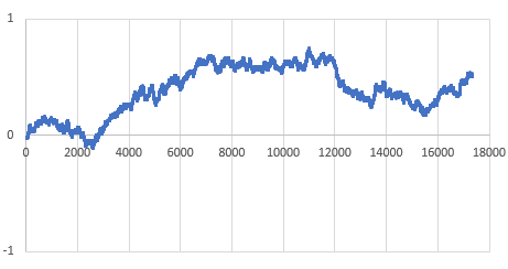
So with the correct aging offset this -M chip could be expected drift less than a second per year. Of course this only applies near our Step1 testing temperature, but in general: If you found the best aging offset correction, the msec difference between a 1Hz alarm from the RTC and the GPS pulse should change very little over a short test.

Its worth noting there is ±2ppm of jitter in the calculation with that -M chip (above) that is not present for -SN chips. The -SN shown below had a straight linear drift of 20 milliseconds slow over five hours when its Aging register was left at the zero default (that’s about 35 seconds/year or 1ppm), but the same RTC had near zero milliseconds of drift over five hours when the aging offset was set to -21:

RTC temp rise during this test
Msec drift approaching zero after 5h, with TCXO adjustment.
Error ppm ~0, with very little jitter on this -SN chip
Error(ppm) vs Runtime(sec): This drift verification on a DS3231-M was done with an age offset of -33 from the Step1 test. The B term in the Excel linear trendline fit is less than the 0.12ppm/bit register adjustment, confirming that -33 is optimal for this chip. The absolute timing change over this 2.5h test was less than 1/2msec faster than the GPS pulse.

Even with temperature rising 3°C during the test, that -SN stays within a tighter tolerance than the -M. This difference in short-term variability explains why the offset determination settles so quickly with a -SN, but can wander around for some time with a -M. The code used here in Step3 is like a slow verbose version of what’s being done in step1 that shows all the intermediate readings. If you put a linear trendline on the graph of the error PPM from running this test with the offset left at the zero default, you can estimate how much age register adjustment it would take to shift those readings until the average is near zero. The aging offset suggested by the test in Step1 should be close to the result of dividing the ‘b’ term from the y=mx+b trendline fit equation by 0.1ppm(SN) or 0.12ppm(M), and changing the sign.

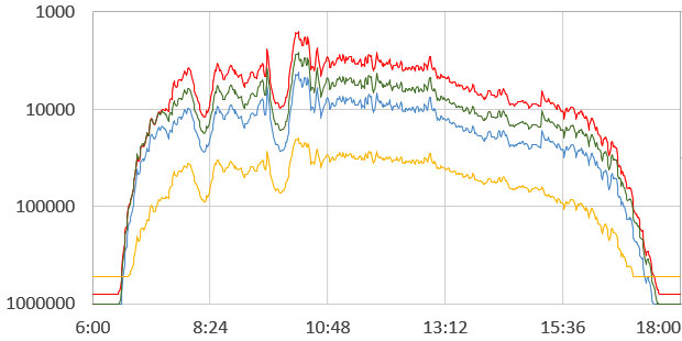
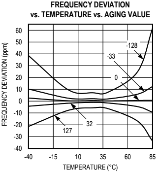
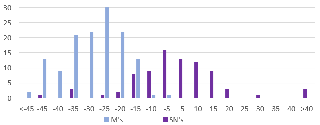
On his blog, NNP also demonstrated how the two chip variants have different responses to temperature changes:

Temp(°C) vs Time(sec): The RTC modules were exposed to this overall pattern although the final tests were run faster (blue = program, orange = PID actual)
Drift Error (ppm) vs Time (sec): The spikes are due to the fact that the TCXO corrections only occur every 64 seconds on the -N variant, but after that the chip quickly returns to its ±2ppm spec.
While still within the rated ±5ppm the -M shows greater variability. With the -M chips doing corrections every 10 seconds I’m surprised the overall TCXO response takes a longer.

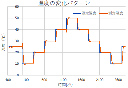
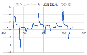
[ images from: http://radiopench.blog96.fc2.com/blog-entry-960.html ]

This confirms what I already suspected from our data: the -SN chips are a much better choice for outdoor environments where temperatures vary over that entire 50°C range. Although the temperature coefficient of the MEMS oscillator is not specified in the datasheet, loggers built with -M chips are probably still fine for stable thermal environments and with a tuned Aging register I’d expect them to drift less than ten seconds per year indoors. There are other insights if you dig into NNP’s blog. For example, drift is also affected by the physical orientation of the chip with respect to gravity. I had no idea it was a problem for all quartz resonators unless the crystal is cut into a special shape to avoid it. This highlights the fact that with so many different factors affecting the RTC, the Aging offset adjustment will never be perfect; you are simply aiming to reduce the ‘average’ drift. These tests are also affected somewhat by the stability of the oscillator on the UNO so we have a chicken & egg thing there.

I will be doing more tests to see what other insights it can give into our ProMini / DS3231 combination. With the ability to synchronize clocks so precisely (in Step 2) you can see the outliers in a group in as little as 24 hours simply by watching the LED blinks. I already do multiple rapid burn-in tests with new loggers as part of pre-deployment testing, so visually checking synchronization during those runs is low-effort way to verify the RTC. One thing I’ve long suspected, but have never seen any actual proof of, is that the process of updating registers and generating alarms also affects the clock time. Perhaps handling the I2C transaction blocks the update of some internal counter? I could test this by setting one logger in a ‘well matched’ group to wake every second, while the others blink at five seconds, and see how many days it takes for the fast blinker to shift out of alignment.

It would be interesting to get a couple of the newer DS3232 / DS3234 chips, and test how much they drift with their TXCO pushed out to 512 seconds for 1µA current, instead of the 64 second default that pushes the DS3231’s up to about 3µA average standby current.


Last Word

With these three tools to wrangle our time series we could see drift as low as five seconds per year from an SN in a stable environment, so our little 328p loggers can finally go toe-to-toe with all those smugly networked ESP32s. I will eventually combine these into a general RTC testing utility, but there are plenty of use cases for each as an isolated step – especially if you were tweaking the code for use with different RTC chips. Likewise, with the Neo being a 3v device I could add a few header pins to our loggers for the serial coms and run everything with the logger alone.

But I’m somewhat sentimental about the original UNOs, so it’s nice to dust them off once and a while. Another factor is that if you run two separate instances of the IDE you can choose a different com ports for each instance. So you can simultaneously have that UNO/GPS combination connected, and a ProMini logger connected via its own UART module. As long as you align the code open in each instance with the appropriate port, you can run those RTC tests on the UNO in the background while you work in the other instance of the IDE. This will be very handy when servicing loggers in the field. I will secure those field calibration rigs with hot glue and make them more compact with a ‘sit-on-top’ protoshield.

The quid pro quo when adjusting the Aging register is that the reduced drift within the tuning temperature range comes at the cost of increasing non-linearity at more extreme temperatures. But the underwater/cave sites we deploy into are quite stable compared to surface conditions, so it’s probably worth the trade. Physical aging rates are not necessarily constant or linear, so I expect that that register will need a yearly update. The first complete generation of fully sync’d & calibrated RTCs will get deployed this fall, so it will be a while before I can check how aging is changed by exposure to real world temperature variation. I’ll be happy if I can get -M’s below 1 second of drift per month under those conditions. I would hope to see the aging stabilize after the first year of operation, in a manner similar to sensor aging.

At the very least, we’ve greatly enhanced our ability to remove any duffers from those cheap eBay parts. I’m still wondering what new sensor possibilities better time discipline might enable but I can already see some interesting labs for the next cohort of e360 students. One of the more challenging things to demonstrate within the constraints of a classroom is the relationship between datasheet error specifications and sensor drift. I’ll set aside a few -M modules for those teaching loggers so the results are more dramatic.


Using a $1 DS3231 Real-time Clock Module with Arduino
A look inside the DS3231 real-time clock by HeyPete
5 Month DS3231 Drift Results at HeyPete.com
Setting the DS3231 Aging register to an optimum value by SermanP
Super-Accurate GPS-Corrected RTC Clock without NTP
Precise measurement of RTC error using GPS from Needle Nose Pliers
How they test Aging Performance in Crystals from Connor Winfield
Choosing the right RTC at Hackaday & module photos at Craft Corner
Comparing DS3231 / PCF8563 / MCP79400 / DS1307 RTCs
A collection of very detailed RTC tests from Dan Drown
And his GPS module measurements Part1, Part2, Part3 and More
An architect’s guide to GPS data formats, Estimating GPS time to FIRST fix
The U-centre program from u-blox, with multiple displays
Can the 60Hz mains frequency be used as a reference?
A Timing-sync Protocol for Sensor Networks
PTP clock synchronization over a WAN backbone
Arduino system clock accuracy [ ±1000ppm], various crystal error specs
RTC seconds/day to ppm drift calculator

Just adding a reminder here: the DS3231 doesn’t have a built-in mechanism to disable alarms after they’ve been set. You can clear the alarm flag to release SQW after it fires, but the alarm will still be armed and will fire again at the next time match – no matter how you set the ‘enable/disable’ bits. The ONLY way to disable alarms on the DS3231 is to load those registers with an ‘invalid’ h/m/s combination that the actual time can never reach (eg: one with minutes/seconds set to 62 or, date set to Feb 31st). You can also set the EOSC bit of the control register to logic 1 which stops the oscillator when the DS3231 is on VBAT power – but you will then be unable to check the clock drift at the next logger download. Halting internal oscillator is the only way to stop the temperature conversions.

From the data sheets you can see that the -M uses half as much power (about 26 milliAmpSeconds/day) as the -SN chip does (45 mAs/d) to do its TXCO corrections however our standard Promini/DS3231-SN module combination usually sleeps around 890 nA while the same logger built with a DS3231-M will sleep closer to 1680nA (when a temp compensation reading is not occurring). A sleeping 328p based ProMini draws ~150nA (reg removed & BOD off) and the 4K AT24c32 EEproms on the modules draw less than 50nA when not being accessed. So the -M chips have more than 2x the ~700nA Ibat timekeeping draw of -SN chips.

DIY Data Logger Housing from PVC parts (2020 update)

Basic concept: two table leg caps held together with 3″ 1/4-20 bolts & 332 EPDM o-ring. Internal length is 2x3cm for the caps + about 5mm for each o-ring. SS bolts work fine dry, but we use nylon in salt water due to corrosion; tightening the bolts enough that the o-rings will expand to compensate for nylons 2-3% length expansion when hydrated. PVC is another good bolt material option if you deploy in harsh environments.

We’ve been building our underwater housings from 2″ Formufit Table Screw Caps since 2015. Those housings have proven robust on multi year deployments to 50m. While that’s a respectable record for DIY kit, we probably over-shot the mark for the kind of surface & shallow water environments that typical logger builders are aiming for.

The additional RTC & SD power control steps that we’ve added to the basic ‘logger stack’ since 2017 are now bringing typical sleep currents below 25μA.  So the extra batteries our original ‘long-tube’ design can accommodate are rarely needed. (described in Fig. A1 ‘Exploded view’ at the end of the Sensors paperIn fact, pressure sensors often expire before power runs out on even a single set of 2xAA lithium cells.

This raises the possibility of reducing the overall size of the housing, while addressing the problem that some were having drilling out the slip ring in that design. Any time I can reduce the amount of solvent welding is an improvement, as those chemicals are nasty:
(click to enlarge)

Basic components of the  smaller 2020 housing cost about $10. O-rings shown  are 332 3/16″width 2 3/8″ID x 2 3/4″OD EPDM (or other compound )

Double sided tape attaches a 2xAA battery pack to the logger stack from 2017 ( w MIC5205 reg. removed, unit runs on 2x Lithium AA batteries)

The o-ring backer tube does not need to be solvent welded. Cut ~5cm for 1-ring build, & 5.5cm for a 2-ring. Leaving ~1.5cm head-space for wires in the top cap.

The logger stack fits snugly into the 5.5cm backer tube with room for a 2 gram desiccant pack down the side.

The screw-terminal board is only 5.5cm long, but the 2x AA battery stack is just under 6cm long.  With shorter AAA cells you can use only one o-ring.

With several 4-pin Deans micro-plug breakouts & AA batteries things get a bit tight with one o-ring. So I add a second o-ring for more interior space.

Sand away any logos or casting sprues on the plugs & clamp the pass-through fitting to the upper cap for at least 4 hours to make sure the solvent weld is really solid. (I usually leave them overnight) Then wet-sand the large O-ring seat to about 800 grit.  Sensor connections are threaded 1/2″ NPT, but I use a slip fit for the indicator LED, which gets potted in clear Loctite E30-CL epoxy w silica desiccant beads as filler. Most clear epoxies will yellow over time with salt water exposure, so for optical sensors or display screens I usually add an acrylic disk at the upper surface.

The only real challenge in this build is solvent welding the pass through ports. In the 2017 build video we describe connectors with pigtails epoxied to the housing.  But you don’t necessarily need that level of hardening for shallow / surface deployments. The potted sensor connections shown in the video (& our connectors tutorial) can be threaded directly to the logger body via 1/2 threaded NTP male plugs. 

Note: Position the NPT risers on the caps directly opposite the bolt struts, and as near to the edges of the cap as you can so that there is enough separation distance to spin the lock down nuts on your sensor dongles. In the photos below I had the pass-through in line with the struts, but with long bolts this may limit your finger room when tightening the sensor cable swivel nuts. These direct-to-housing connections do make the unit somewhat more vulnerable to failures at the cone washer, or cuts in the PUR insulating jacket of the sensor dongle.

Threaded bulkhead pass-throughs get drilled out with a 1/2″ bit. Alignment with bolt struts shown here is suboptimal.

This closeup shows a slight gap near the center – I could have done a better job sanding the base of the NPT to make it completely flat before gluing & clamping!

the pass through style sensor cap mates to the the lower half of the housing. We’ve always used our o-rings “dry” on these pvc housings.

I describe the creation of the sensor dongles with pex swivel connectors in the 2017 build video series.

Dongle wires need to be at least 6cm long to pass completely through the cap.

“2-Cap” housing: Aim for 5 to 15% o-ring compression but stop if there is too much bending in the PVC struts.

It’s also worth noting that there are situations where it’s a good idea to have another connector to break the line between the sensor and the logger. (shown in 2017)  We often mount rain gauges on top of buildings with 10-20m of cable – so we aren’t going to haul the whole thing in just to service the logger. But on-hull connections like the ones shown with this new housing necessarily open the body cavity to moisture when you disconnect a sensor, and nothing makes a tropical rainstorm more likely to occur during fieldwork than disconnecting the loggers that were supposed to be measuring rainfall.

With a double o-ring and additional seal(s) in the cap, we probably won’t be deploying this new design past ~10m. Given how quickly they can be made, this short body will be a standard for the next few years; perhaps by then those fancy resin printers will be cheap enough for regular DIY builders to start using them – at least for shallow water work.  For now we’ll continue with the long body style for deeper deployments or remote locations that we might not get to again for a long time. The second o-ring is not really necessary if you make a nice tight stack when you assemble the logger.

In general I’d say these ‘plumbing part’ housings reach their long term deployment limit at about ~60m because the the flat end caps starts blowing noticeably at that depth. That overlaps nicely with the limit of standard sport diving, but if your research needs more depth it’s worth looking into the aluminum body tubes/endcaps becoming available in the ROV market. As an example:  Blue robotics makes some interesting enclosures if you need clear acrylic endcaps for camera based work.

(UPDATE: the double o-ring shown in the photo above was required when using 3.5″ bolts. That was a mistake as they tended to extrude easily.  Using shorter 3″ bolts lets you go with only a single o-ring which is gives you a solid seal with no accidental extrusions.)

Addendum 2023-05-25

We needed a way to see how far we could take the new falcon tube loggers and water filter housings are a good solution as the domestic water pressure range of 40-80psi overlaps nicely with sport diving depths. The internal clearance of the filter housing we used is slightly larger than 4.5″ x 9.5″ so could accommodate these older PVC style housings as well:
https://thecavepearlproject.org/2023/05/24/a-diy-pressure-chamber-to-test-housings/

A household water filters make a good low-range pressure chamber.

Pro Mini Logger Project for the Classroom [ EDU Jan: 2019 ]

Note: An updated tutorial was released in 2020:  CLICK THIS LINK to view that version


“Instrumentation is a central facet of student, amateur and professional participation in science. STEM education, recruitment of scientists and experimental research are thus all hampered by lack of access to appropriate scientific hardware. Access restrictions occur because of: 1) lack of capital to purchase or maintain high-cost equipment, and/or 2) the nature of proprietary ‘black box’ instrumentation, which cannot be fully inspected, understood or customised…
…In addition to reducing opportunities for people to engage with science, this lack of access to appropriate hardware restricts scientist’s creativity in experimental designs.”

From: Journal of Open Hardware
Expanding Equitable Access to Experimental Research and STEM Education

by Supporting Open Source Hardware Development


Last year’s intense deployment schedule focused on getting more sensors into the field, which left little time for development of new approaches to the logger itself.  Now that everything is settling into the school term routine, it’s time to update the “classroom edition” of the Cave Pearl Logger with feedback from three years in the trenches: 

The 2016 build achieved it’s goal reducing construction time, but it was low on important skills like soldering. Limited lab time meant that something had to give if we want students to “pay the iron price” for their data, so we’ve added a pre-made enclosure box. Though it’s not as robust as the PVC housings, it provides more room inside the housing. Past student projects have required things like 555’s, ADS1115 modules, display screens, etc. and the proto-board will make it easier to integrate those additional components.

PARTS & MATERIALS

TransparentSinglePixl
Bill of Materials: $18.35
Plano 3440-10 Waterproof Stowaway Box
Usually cheaper at Amazon as “add-on” items.  $4.96 at Walmart and there are a selection of larger size boxes in the stowaway series. 6″ Husky storage bins are an alternative option.
$5.00
4Pin 24AWG IP65 Black Waterproof Cable Connector OD 4mm
Better quality version is available at Adafruit for $2.50 each, wBL-RED-Wht-Yel colors used here for the I2C bus.
$1.00
M12 IP68 Nylon Cable Gland
Adjustable for 3mm-6mm diameter. You need two for the build. Make sure they include O-rings.
$1.00
3/4″ Schedule 40 PVC Cap
Diameter will depend on the size of your sensor breakout board. Get ones with FLAT ends.
$1.00
White 170 Tie-Points Prototype Breadboard
Available in other colors.
$0.60
Pro Mini Style clone 3.3v 8mHz
Get the ones with A6 & A7 broken out at the back edge of the board.
$2.20
Nano V1.O Screw Terminal Expansion Board
Note: To save time, you can spend an extra $1 for pre-assembled boards by Deek Robot, Keyes, & Gravitech (CHECK: some of them have the GND terminals interconnected)  Have a few small flat head screw drivers handy.  
$1.05
DS3231 IIC RTC with 4K AT24C32 EEprom (zs-042)
Some ship with CR2032 batteries already installed.  These will pop if you don’t disable the charging circuit!  
$1.25
CR2032 lithium battery  $0.40
4 poles/4 Pin 2.54mm 0.1” PCB Universal Screw Terminal Block Connector
These things look “open” when they are “closed”, and you need a very small screw driver to open them.
$0.40
SPI Mini SD card Module for Arduino AVR
Buy the ones with four ‘separate’ pull-up resistors so that you can remove them.
$0.50
Sandisk or Nokia Micro SD card 256mb-512mb 
 Test used cards from eBay before putting them in service. Older Nokia cards have much lower write currents in the 50-75mA range. This is less than half the current you see on more common larger sized cards.
$2.00
3×1.5V AAA Battery Batteries Holder w Wire Leads
The Pro Mini regulator will handle battery packs holding from 3 to 8 AA or AAA batteries. If you are using alkaline AAA batteries, changing this to a 4xAA battery holder doubles the run time.
$0.40
Common Cathode Bright RGB LED 5mm 
( & 4k7 limit resistor) 
$0.05
3M Dside Mounting Tape10MΩ resistors & 3MΩ resistors, 22awg silicone wireheader pins, etc… $0.50
Donation to Arduino.cc
If you don’t use a ‘real’ Pro Mini from Sparkfun to build your logger, you should at least consider sending a buck or two back to the mothership to keep the open source hardware movement going…so more cool stuff like this can happen!
$1.00
Comment:   You might need some extra parts to get started:                (not included in the total above)
2in1 862D+ Soldering Iron & Hot Air station Combination
a combination unit which you can sometimes find as low as $40 on eBay.
Or get the Yihua 936 iron alone for about $25.
$50.00
3.3V 5V FT232 Module
  ***Be sure to set the UART module jumpers to 3.3v before using it!*** and you will also need a USB 2.0 A Male to Mini B cable.
$2.75
Micro SD TF Flash Memory Card Reader
Get several, as these things get lost easily. My preferred at the moment is the SanDisk MobileMate SD+ SDDR-103 which can usually be found on the ‘bay for ~$5.
$1.00

Connection Diagram:

This logger uses the same three components described in the paper from 2018, but we now connect those core modules via a screw-terminal expansion shield, rather than soldering them directly to the pins:
 
COMPONENT PREPARATION

Watch through the videos as a complete set first so you know where you are going, and then use the images below the videos to remind you of the key steps while you do the assembly; It usually goes much faster working from a photo where you can see all the connections at once. The times listed are estimates for people with soldering experience. If you’ve never built a circuit before, then taking 3-4x that long is completely normal. Don’t worry about it – you will be surprised how much faster you get with a little practice!

Screw Terminal board:  (~40min)  or ( 5min with pre-assembled board)

Don’t forget to measure the values of the resistors before soldering that voltage divider. You will need those values to calculate the battery voltage based on the ADC readings from pin A6.

These screw terminal boards are designed for an Arduino Nano, but if you orient the board to the Tx/Rx pins, the labels on digital side of the shield will be correctly aligned with the Pro Mini:

The most common beginner errors at this stage are crooked headers & not heating the pad/pins long enough for solder to flow properly.  This is often because students are trying to use an iron tip that has “gone dry” so the heat is not transferring properly to the pins. You must protect soldering iron tips with fresh solder every time you put it in the stand to prevent oxidation. Tip Tinner can sometimes restore those burnt tips.   {Click images for larger versions}

Common soldering errors – which are easily fixed by re-heating with more solder & flux.

Divider runs between GND & RAW Vin, with output to A6 pin.

Always apply conformal coating in a well ventilated space, such as a fume hood.

It is better to err on the side of using a little too much heat, because partial connections to the screw terminals will cause you no end of debugging grief later: Cold solder joins can “sort of” work “sometimes”, but cause mysterious voltage drops over those points because they can act like randomly variable resistors in your circuit.  Note: This voltage divider uses meg-Ω size resistors and takes >1 second to charge the capacitor when the unit is first powered on – so you can’t take the first battery reading until that much time has passed.

The Pro Mini Board:   (~40 min)

~5-10% of the cheap Pro Mini clones from eBay are flaky, and it is quite annoying to discover one of those that after you have assembled a logger. So test your board with the blink sketch before you remove pin13 LED resistor.  These limit resistors move around from one manufacturer to the next, so you might have to go hunting for them on your particular board.  You also need to remove the RESET switch from the board, or that button will be compressed when you put the SD card adapter in place:

Test w blink sketch!

You can skip the reset pins at this stage, or you can pull those pins out of the plastic rails later with pliers, or simply cut them off.

SCL & SDA jumpers to the 2 extra pins on the digital side.

Connect A6-7 & GND to analog side pins with the leg of a scrap resistor.

(Note: Credit goes to Brian Davis for the idea of using “extra header pins” when patching to the unused to screw terminals.)    

The SD Card Adapter:   (~15 min)

This SD card adapter comes with small surface mount pull-up resistors on the MOSI, MISO & SCK (clock) lines (removed from the dashed red line area photo 2 below).  The Arduino SDfat library uses SPI mode 0 communication, which sets the SCK line low when the logger is sleeping. This would cause a constant drain (~0.33mA) through the 10k SCK pullup on the module if we did not remove it.  I prefer to pull MOSI & MISO high using the internal pull-ups on the Atmel328P processor, so those physical resistors on the breakout board can also be removed. Leave the top-most resistor of the four in place to pull up the unused DAT1 & DAT2 lines.  This keeps those unused pins on the SD card from floating, which can draw excess current.

Only remove the bottom three pullup resistors. keep the top one
The SPI connections:
RED:           3.3v regulated
Grey:          Cable select (to D10)
Orange:     MOSI   (to D11)
Brown:      SClocK (to D13)
Purple:      MISO   (to D12)
BLACK:     Ground

Attach SD adapter & Pro mini to the Screw Terminal Board:  (~20 min)

Label the Vcc & GND connections with a colored marker, then insert the Pro Mini into the headers on the screw-terminal shield. Be careful not to bend the pins – especially the “extension” pins at the back of the board. It’s easy to connect the board in the wrong orientation at this step. The voltage divider on the bottom of the screw terminal shield aligns with the ANALOG side of the Promini board. 

Label the Vcc & GND connections.

Then affix the SD adapter board to the top of the Pro Mini with a slight overhang, so that the jumper wires align with the screw terminals below. Trim the wires about 1cm past the edge of the board to provide enough stripped wire for the terminal connection.

The limit resistor for the common cathode RGB can range from 4k7 to > 30kΩ

LED on pins D4-D6, & GND. NOTE: Grounding the LED through D3 lets you use the LED as a sensor and support for this is included in the base code.  Also see: multiplexing wD9 GND

Add layers until the tape extends beyond the pins. This might require 3 layers of tape.

The RTC Module:  (~15min)

The simplest modification to these DS3231 RTC boards is to remove the charging circuit resistor and power LED limit resistor from the circuit board (the red squares in the first picture).  A non-rechargeable CR2032 coin cell battery will supply the RTC with power for many years of operation.  Note: The 32K pin is not connected, and does not get a jumper wire. The four screw terminals go on the same side as the battery holder.

rtc1

An alternative to the 4-pin 0.1” screw-terminal block is to solder the I2C pass-through wires directly to the module.

Cutting the RTCs Vcc pin reduces sleep current by ~40% – this step is completely OPTIONAL!

Add an extra layer of foam tape over the smaller 4K eeprom chip, so that the thickness matches the top surface of the DS3231 chip.  The RTC board already has 4.7kΩ pull-ups on the SDA (data) and SCL (clock) lines so you will not need to add them to the bus.  This module also has a 4.7k pull-up on the SQW alarm line. Adding the screw terminals to the small cascade port on the RTC module is another creative idea from Brian D, but you could just add straight pin headers: If you don’t want to make your own crimp ends,  4-pin JST XH series connectors have a pitch of 2.5 mm which is effectively identical to the 0.1″ pitch of those Dupont pins. 

The Plano Stowaway housing: (~10 min)

In these photos, I’ve melted threads into the housing for a pass-through with a cable gland, but that is entirely optional. This trick works with many different housing materials, but it takes a bit of practice to figure out what the right temperature is for any given one. The plastic in the plano boxes melts quite easily, so be gentle with the heat gun. Glands much larger than PG7 (12mm) will not fit in the available space in that corner.

These two cable glands have matching thread specifications

Heat only the threads from the metal cable gland with your heat-shrink gun & a pair of pliers

Gently twist the threads into the plastic of the Plano-box & as soon as it’s through blow on the metal until it completely cools

After cooling,  unscrew the metal threads

Cut away excess plastic burs with a sharp knife and thread the plastic cable gland into place.

You may need two washers due to the curvature of the box. The cable gland shown above is an M12 x 1.5 IP68 for 3-6mm dia. cables (also desc. as PG7 12mm)

Strategically placed holes in the clips provide zip-tie locations to secure your logger.

Holes for Zip-tie securing

ASSEMBLING THE LOGGER PLATFORM:  (~30 min)

Using double sided tape to hold the parts inside the housing (rather than traditional stand-offs) makes this stage of the build remarkably quick.  Adding male Dupont pins allows you to join internal and external wires via the breadboard.  Be sure to use wires that are long enough to reach the mini breadboard. 

Bowing on some boxes can reduce the contact patch on the battery holder, if so try adding another layer of  tape, or upgrade to 30LB.

You can “reactivate” spent desiccant packs with a few zaps in the microwave – if they have indicator beads.

Connecting external sensors to the housing:

It’s worth mentioning the breadboard contacts are notoriously sensitive to vibration, etc. Once your testing stage is complete, and your prototype is working as it should, bring those  sensor wires directly over to the screw terminal connections for a more secure connection.  Also remember to put protective tape over any sensor ports that need to remain open before potting those sensor boards in epoxy. Otherwise you might clog the sensor by accidentally letting a drop fall into it.

Your Logger is ready!    (~2 to 2.5 hours)

Now you can test your new logger to confirm all the connections are working:

1. Test the LED – Edit & upload the default blink sketch, changing the pin numbers each time to match your RGB LED connections.

2. Scan the I2C bus – with the scanner from the Arduino playgound. The eeprom on the RTC module is at address 0x56 or 57 and the DS3231 should show up at address 0x68. If you don’t see those two devices when you run the scan, there is something wrong with your RTC or the way it’s connected.

3. Test the EEprom on the RTC module – We’ve updated BroHogan’s original code from the playground to this tester script. You may have to change the I2C address at the start of the code based on the numbers shown during your I2C bus scan. The AT24C32 will store 4Kbytes, and has a 32-byte Page Write mode which accommodates the maximum of 30 bytes you can transport the wire libraries I2C coms buffer.  Make sure you don’t do eeprom page-writes that pass over the physical page boundaries set by that eeproms 32 byte block size. If you are ready for the added code complexity, buffering data to the eeprom can dramatically cut down on the number of SD card saves, however the eeprom communications are so slow that sometimes it ends up using the same amount of power as simply writing your data directly to the SD card directly.

An alternative parts arrangement for the classroom logger that makes room for a larger 4xAAA battery holder and DUPONT style connectors. It’s easy to move things around to suit your own projects, and rotating the breadboard gives you room for larger battery holders & longer operating times. Note: For most 1.5V alkaline batteries, (voltage-1)*200 will give you the approximate percentage of total capacity remaining.

4. Set the RTC time, and check that the time was set – There are dozens of good Arduino libraries you could use to control the DS3231, and there is a script over at TronixLabs.com that lets you set the clock without a library. The trick with Tronix’s “manual” method is to change the parameters in setDS3231time(second, minute, hour, dayOfWeek, dayOfMonth, month, year);  to about 1-2 minutes before the actual time, and then wait to upload that code till about 10-15 seconds before your computers clock reaches that time (to compensate for the compiler delay). Open the serial window immediately after the upload finishes, and when you see the time being displayed, upload the examples>blink sketch to remove the clock setting program from memory – otherwise it will keep resetting the RTC every time the Arduino re-starts.  [ Note: hour  in 24-hour time, & year with two digits eg: setDS3231time(30,42,21,4,26,11,14);  ]

5. Check the SD card is working with Cardinfo – Changing chipSelect = 4; to chipSelect = 10;
Note that this logger requires the SD card to be formatted as fat16, so most 4GB or larger High Density cards will not work. Most loggers only generate 5 Kb of data per year anyway.

These breadboard connections are really vulnerable to vibration, so for quick back-yard tests of a rough prototype I sometimes add a tiny spot of hot-melt glue to stabilize the components. Breadboards add about 2-4pF of capacitance for side by side rows so the rule of thumb is you shouldn’t run protoboard circuits much faster than 1 MHz.

6. Check the sleep current – With an SD card inserted in the logger, upload this Pro Mini datalogger starter script with no changes (note: that code requires you to install three libraries as well). Then connect an ammeter between the positive battery connection and the Vin screw terminal (you will need an extra wire to do this) and run the logger from the AAA or AA battery pack.  After the initialization sequence has finished, the reading on the screen (in milliamps) is your loggers sleep current.

AAA cells usually provide about 1000 milliamp-hours of power to their rated 0.8v, but we are only using half of that from alkaline batteries with a regulator input cutoff up at 3.6v.  So dividing 500 by your loggers sleep current gives you a rough estimate of your loggers operating life (in hours).  For a more accurate estimate, you can use one of the Battery Life Calculators on the web with 250ms @5mA for your sample time.  Changing the power supply to 4xAAA cells lets you bring alkalines down to 0.9v/cell, extracting almost the entire 1000 mAh. Lithium AAAs deliver almost their entire capacity above 1.2v/cell so 3xAAA lithiums yield almost 1000 mAh capacity even with the 3.6v input cut-off.

Thermal response of 3x AAA’s (mV left axis) vs Temp (°C right axis) in the standard voltage-regulated classroom build running the starter code from GithubThe 90mv drops caused by SD card “controller housekeeping events” at 20°C  increase to ~220mV as temps near -15°C. These periodic high drain (100-200mA) events would likely trigger the low-voltage shutdown before anything else in the loggers normal duty cycle. (Note: Battery readings taken AFTER SD save, Sample interval: 1 min, sleep current for this test unit: 0.22mA )

Its worth noting that the starter program we’ve provided captures an ambient temperature record from the RTC in 0.25°C increments (example right).  New sensor readings can be added to the log file by inserting:
file.print(YourSensorVariableName);
followed by a separator file.print(“,”);
in the main loop before you close the datafile on the SD card. Then change the text in the dataCollumnLabels[] declaration to add headers to match your new data. This starter script automatically generates required data files on the SD card at startup, and tracks the rail voltage for those adventurous enough to run without a regulator. SD memory is electrically more complex than the Pro Mini processor, with some using a 32 bit arm core.

Once you have your logger running, you might want to review our tutorial on adding sensors to your data logger. And after that you’ll find a few more advanced I2C sensor guides on this site as well (…and the list is constantly growing) We’ve also developed methods to add 5110 LCD & OLED screens to the Cave Pearl Loggers using the fewest system resources. These screens are easily accommodated on the proto-board in this build.

For people wanting to take their skills farther, you can explore the gritty details of how we optimize these loggers for multi-year deployments in the 2018 Sensors article (free to download). The research loggers are a more challenging build, that fits inside an underwater housing made from PVC pipe

Addendum: Power Management (Optional)

On the standard build described above, the Pro-Mini’s MIC5205 power regulator should deliver  sleep currents below 0.25 mA (Pro Mini ~0.05 mA + sleeping SDcard ~0.05-0.09 mA + RTC ~0.09 mA). That should reach several months operation on 3 AAA cells before the batteries reach the regulators 3.4v input cut-off.  I usually have regulated loggers go into shutdown mode at ~3.6v to reduce the chance of leaks, because alkaline batteries often spill their guts when they reach 1v/cell.

There are a couple of relatively simple modifications to the basic logger that more than double the operational time – but they both come with important implications you should understand fully before adding them to your project. The RTC mod is relatively safe, but running a datalogger from a raw battery supply is not for the faint of heart. 

1) Cutting the VCC leg on the DS3231 chip forces the RTC to run from the coin-cell. >Set Bit 6 of CONTROL_REG 0x0E to enable wake alarms from the backup battery!

2) Remove the regulator: few LDO’s have reverse current protection & most regs leach 30-90 uA if the voltage on output line is  higher than on their input

2) Then connect the positive wire from a 2X LITHIUM AA battery pack directly to the Vcc rail on the Pro Mini

The DS3231 RTC was designed to handle power supply failures by switching over to the backup coin-cell battery, and it enters a special 3uA “timekeeping mode” to use less power in that situation. However the chip is still fully capable of generating alarms (provided you set the Battery-Backed Square-Wave Enable bit of CONTROL_REG 0x0E to 1) , and of responding to the I2C bus at 400 mHz. So if you cut the main power leg on the RTC you reduce the loggers sleep current by almost 0.1mA (~40%). The trade-off is that your loggers operation is now entirely dependent on the 200mAh CR2032 coincell to keep the clock delivering wake-up alarms when you are also asking it to deal with pulsed loads in the 80 uA range every time you communicate over the I2C bus. The RTC also can not generate temp-corrected frequency outputs on the 32kHz pin when operating from the coin cell.

Here drops of hot glue secure the RTC coin cell battery against accidental resets. It’s worth noting that even with this precaution, we still see 1-2 units out of 10 loose their time when they have to be transported in airline luggage.

Another quid pro quo here is that coin-cell holders occasionally lose contact very briefly under vibration, so if you cut the Vcc input leg – add  a  0.1 μF capacitor (ceramic 104) across the coin-cell holder pins. That will give you about 80 ms coverage, which should be longer than the holder will lose contact. Otherwise a hard bump can reset the RTC back to its Jan 01 2000 default.  The wake-up alarms usually continue after that kind of reset, however fixing an entire years worth of time series data based on your field notes is a pain in the backside.  Real world installations often involve this kind of rough handling, so I prefer a more advanced RTC modification that keeps two power lines feeding the RTC.  But for more “gentle” deployments, simply cutting the chip’s vcc leg & adding a couple of drops of hot glue OK. Write the installation date on the coin cell with a black marker. I do this to all of my batteries now…

For loads in the 0.1mA range, the MIC5205 is less than 60% efficient. So the other modification is to remove the voltage regulator and run the entire system from 2x LITHIUM AA batteries.  Lithium batteries (like the Energizer L91) have two characteristics that make them well suited to this approach: 1) they have an extremely flat discharge curve, yielding >75% of their power before the voltage falls below 1.5v/cell on the lower plateau and 2) a pair of brand new lithium cells gives a combined voltage right at 3.6 volts. If you look at any of the SD card manufacturers’ specifications, they all specify a voltage range of 2.7v to 3.6v.  At 8 MHz the ATmega328P processor on the ProMini supports voltage levels between 2.7 V and 5.5 V. Both of these ranges overlap beautifully with the lithium cell’s discharge curve. If you are using ratio-metric analog circuits then the voltage fluctuation over time will not affect your readings, but if you need absolute measurements then use the internal voltage reference as Aref.  Digital sensor levels are based on a percentage of Vcc, so they are relatively insensitive to voltage variations.

Here I’ve done both modifications to the basic build, and brought the sleep current (with no sensors) from an unmodified starting point of 228μA, down to 80μA. Most of that remaining power is due to the sleeping SD card, since the Pro Mini only draws about 5μA in deep sleep mode. Using only 1/2 of the 3000 mAh capacity of a typical AA Lithium pack would keep a logger that sleeps at 0.1mA alive for more than a year, and my rough estimate is that the RTC mod will get you at least twice that much time from a new Cr2032 cell – with a typical 5-15 minute sampling interval.      [NOTE: I’m using an EEVblog uCurrent here to display the μA sleep current on a DVM as milivolts. It’s an exceedingly useful tool that lets you read sleep currents into the nano-amp range without adding the burden voltage you’d see from putting your meter directly into the circuit ]

Even with one less cell powering the system, getting rid of the MIC5205 yields a 25-30% reduction in sleep current for a typical build. While this is very close to the reduction you get from changing to a more efficient regulator like the MCP1702, the other cool thing about this mod is that the processor on the Pro Mini can take a reading of it’s rail voltage by comparing it to the 1.1v internal band-gap reference. So all you need is a little bit of code, and you can keep track of your rail=battery level without a voltage divider, although for accuracy you should take a reading of the actual band-gap voltage using a utility like the CalVref sketch from openenergymonitor.

(NOTE: that Atmel provides no specs on the long term stability of the bandgap ref. and even OpenEnergy no longer uses the internal 1.1vref because v.regulators offer more long-term stability.  ALSO NOTE that genuine Sparkfun ProMini’s have an SJ1 jumper that lets you disconnect the reg simply by de-soldering a pad on top of the board , but clones rarely have that feature.) 

Unlike alkaline batteries, lithium cells have very little voltage droop with brief loads below 100mA, but it’s still a good idea to protect your SD card from potentially data corrupting brief low voltage spikes with a capacitor.  The formula for figuring out how much the voltage across a capacitor will drop is  ΔV = current(A)*time(sec)/C(farads) – but you need to decide how much your supply can drop to know how big to make the capacitor.

Adding a 47uF (or larger) on the microSD rails should keep the shortest transients under control, and once the system reg. has been removed running a jumper between Vcc & Raw recruits the orphan (10uF tantalum) capacitor from the input side of the (now removed) regulator.  Always check the supply voltage before the data saving begins and perform a low voltage shutdown when the lithium pack reaches 2875mv. (ie: at least 150mv above the SD’s 2.7v safe writing minimum). Generate a new data file every couple of weeks so only the last one is vulnerable during the write process. 

2x LITHIUM AA’s (mV left axis) vs Temp (°C right axis) supplying power to an unregulated build running the same code from GithubThe key observation is that the initial 50mv supply voltage variation recorded at 22°C increases  ~100mV at temps near -15°C. For Lithium chemistry batteries with flat discharge curves, the voltage-drop under load is often a better indicator of the remaining battery capacity than the cell voltage. (Readings taken AFTER SD CARD SAVE, Sampling every 1 min, overall sleep current 0.17mA   Note: the 200mv baseline drop on the cells is slightly exaggerated here because low temps increase the bandgap slightly) 

Of course everything has a price, and removing the regulator means you’ve not only lost your reverse voltage protection – you also need to think about how all the components in your system will respond to a decreasing supply voltage over time. Ratiometric analog circuits using the rail as Aref handle this well, but even if you want to use the 1.1v bandgap ref – you already know what the rail voltage is, so you can easily throw a compensation factor into the calculation.  The real problem is that when 2.7 – 3.6v is listed on the spec sheet for a digital sensor – that’s no guarantee the readings will be consistent when the supply voltage changes.  You could have very different error percentages at the high & low end and ambient temperature fluctuations could push your batteries through significant voltage changes every single day (lithium cells are more resistant to this than alkaline).  According to Murata the 8Mhz system clock will remain stable: “Unlike RC or LC circuits, ceramic resonators use mechanical resonance. This means it is not basically affected by external circuits or by the fluctuation of the supply voltage.” 

Testing is the only way to find out if your sensors can handle the variation, and if you don’t have time for that it might be worth keeping that voltage regulator on board despite the reduced lifespan. For field units, I usually replace the MIC5205 with a more efficient MCP1700 regulator because I want all the data consistency I can get.  Another thing to keep in mind when you are hoping for a really low-power build is leakage currents through leftover flux – it’s always worth the time to get your parts squeaky-clean during construction.

Addendum 2019-02-21:

A teacher friend asked us for a version that was less dependent on soldering because they didn’t have the budget for a classroom set of soldering stations. So we’ve worked out a 1 hour “simplified build” of this logger that uses crimped Dupont jumpers to reduce assembly time:

We’ve also added support to the starter code for using the indicator LED as a light sensor, but this requires that you ground the indicator LED’s common cathode through a digital pin (usually D3) , rather than directly to GND as shown in the tutorial above. Also note that the technique relies on the very tiny internal capacitance inside the LED (typically 10 to 15 pF) so you need to connect the LED  right to the screw terminals (ie not the breadboard).  Then you can gather three-channel light level data like this:

Readings from an RGB LED deployed outside in our back yard on an overcast day with two light snow fall events. The yellow line is from an LDR sensor in the same logger that was over-sampled to 16-bit. In this case the clouds & snow acted as a near perfect light diffuser, but in normal weather I’d have placed a thin white teflon sheet over the LED sensor to smooth out the readings. Adding an IR led to the logger lets you create a transmission-based NDVI variant that discriminates the amount of chlorophyll in plant leaves.

These readings are arbitrary time-based units that are completely dependent on your particular hardware combination and system voltage. If you go down the DIY sensor rabbit-hole, you might want to calibrate against the NOAA observations for your area, which includes hourly data for thousands of stations. The data includes temperature, dew point (from which you can compute relative humidity), wind speed & direction, and you can calculate solar position.

Addendum 2020-08-18:
We’ve found that the seal on some of the Plano boxes needs a little help, or current leakage via surface moisture shorts out the LED light sensor readings. In the worst cases leakage lets in enough water vapour to chew through your desiccant pack in less than a week. A little bead of silicone under the o-ring corrects that problem:

Gently pry the O-ring loose so we can add some sealant.

Bead only needs to be 3-4mm in diameter.

Close the housing & let the sealant set for a few days. The improved seal is especially visible at the corners

If you already have your logger assembled, try to find a better quality silicone sealant that does not off-gas acetic acid (smells like vinegar) which could harm the circuits. If you are preparing empty boxes before the logger assembly, then any regular bathroom sealant will do provided you give it about a week to finish curing. I usually choose silicone rated for outdoor applications as they have better resistance to breakdown from UV exposure.