

I was pretty pleased about coming up with a new dithering method that lets you over-sample thermistors to better than 0.002°C with an Arduino. I was bragging about this to a programmer friend recently, and suggested that achieving this with nothing more than a resistor on a pin might annoy engineers who’ve used more complicated circuits for essentially the same job. His response to this surprised me:
“Actually, the ones you’re really going to piss off are the coders. It seems to me that your pin-toggle technique only works because the rail stabilization on those chips is bad. In my business, that’s known as ‘Coding to a Fault’. You see, I spend my days trying to keep large systems on their feet, and these are a patchwork of woolly legacy code and new functions tied together by utilities passing data back and forth. Errors creep in, and that’s expected, because those translators necessarily have to change the format of the data. Often the coder who did the tweening knows about these issues, and documents them, but their manager won’t authorize time for a proper fix once the function is stable because it’s judged to be a harmless, non-lethal error, and the budget’s too tight. Ten years later, it lands on my plate because some diligent person finally decided to take that issue off the bug-list, usually because it was getting on their nerves that the person before them had done such shoddy work. Of course by then the error’s been present in the system so long that other working groups have unwittingly written code that relied on the artifact. So fixing the original problem causes a heap of trouble five steps down the line. Those situations are the bane of my life…”
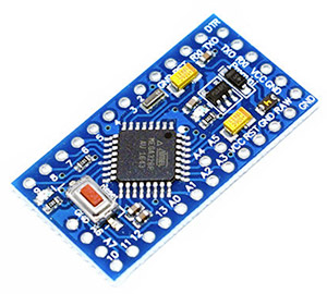
This 8 MHz 3.3V clone works well with the two-clock method. I think of these as simply a cheap breakout board for the 328P.
He had more to say on the matter, but I missed the rest because I was backing away from his increasingly animated gesticulations, which were punctuated by some weird facial ticks. I paused for a moment at the front door, thinking I should at least thank him for the coffee, when “…in fact, I should probably take you out of the technological gene pool right now, before you spread this madness…” convinced me otherwise. I finally understood why the engineers were so critical about this project, since the way I build our loggers ignores several of rules that they’ve dedicated their career to. If I had any professional decency, I’d seek absolution by dumping all that eBay crap in the bin, and abstain from any future component purchases that lead me away from the righteous ±1% path.
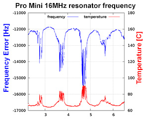
A divine revelation from Rantwijk’s site.
But I have to confess – the devil is still finding work for these idle hands. Especially after reading Joris van Rantwijk’s analysis of Arduino clock frequency, when I realized the resonators on cheap Pro Mini clones probably had so much thermal variation, that you could base a temperature sensing method on that alone. The key insight here is that the $1 DS3231SN boards I’m getting from eBay are the genuine article with ±2ppm stability. By using both of those components in the same device, I had a high accuracy angel on one shoulder and a high resolution daemon on the other.
DS3231’s can be set to output a 1Hz pulse on SQW simply by zeroing the control register:
Wire.beginTransmission(104); //DS3231 RTC address
Wire.write(0x0e);            //control register
Wire.write(0);               //zeroing all bits outputs 1 Hz on SQW
Wire.endTransmission();
To build the temperature sensor, all I had to do was compare that thermally stable 1-Hz pulse to the corresponding number of system clock ticks from the rubbish oscillator on the Pro Mini clone. A dive into the programming forum at Arduino.cc led me once again to Nick Gammon’s site, where his page on Timers and Counters provided several ways to measure the frequency of pulsed inputs. This isn’t the first time I’ve spent a few days learning from Nick’s examples, and I own him a huge debt of gratitude for his insightful work.
I was already familiar with the hardware interrupts on D2 & D3, but the 328P’s input capture unit on D8 does the job with a special circuit that saves the timer values in another register. You then read back that frozen value, and it doesn’t matter how long after the interrupt executes, or what you do in that interrupt, the captured time is still the same. This lets you measure duration to a temporal resolution approaching two ticks of your system clock. (see reply #12 on Nick’s page)
Will the regulators temp-coefficient affect the oscillator?
Oscillators are sensitive to input voltage as well as temperature, but Rantwijk also looked into that, determining that the clock frequency on his 16 MHz Pro Mini varied by about +2.5 Hz / mV input. The MIC5205 LDO on the Mini & most of the 3.3V clones quotes an output Temperature Coefficient [∆VO/∆T] of 40 ppm/°C. If I restrict my sensing range from 0-40°C, then my regulator’s voltage output would be expected to vary by about 0.00004*(3.3 output Voltage/°C) = 5.28 mV over that 40° range. Multiplying Rantwijk’s observed 2.5 Hz/mV *5.28 mV suggests that thermal effects on the regulator would cause less than 14 Hz of variation. Given that he was seeing a variation of several thousand Hz in the ceramic oscillator over a similar temp. range, regulator based thermal errors can be considered negligible.
What about freq. variation due to your decreasing battery voltage?
I had to go digging to figure out what kind of effect a decreasing battery voltage would have. The 5205’s data sheet lists a line regulation [ ∆VO/VO ] of 0.05%. Since my rail is at 3.3v, that suggests a rail variation of about 165 mV over inputs between 3.65-12V. With Rantwijk’s 2.5 Hz / mV benchmark, that would cause about 400 Hz of frequency variation over the entire input range the 5205 will support. That’s about 10% of the expected clock frequency delta. I should see less than 1/3 of that error since the batteries I’m using will only swing from 3.65-6v, but three percent is significant so I’m going to need some way to compensate for main battery discharge. My freezer testing also sees a 0.5V drop on alkaline supply batteries when they get cold, but provided I use the same chemistry during my calibration & deployment runs, voltage “droop” from ambient temperature should be included in the calibration.
Will it Blend?

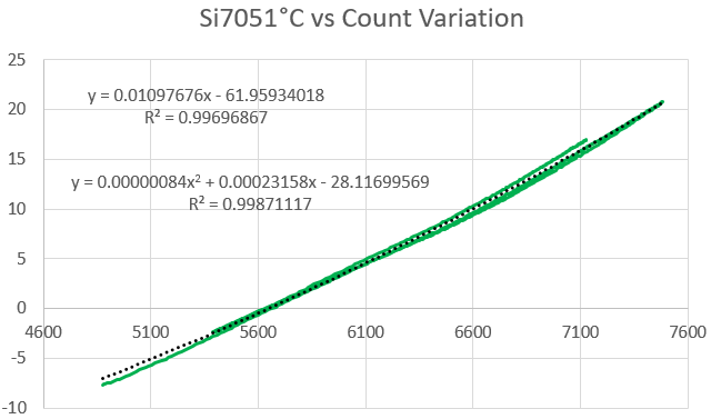
This graph was created by counting the number of system clock tick during a 1Hz pulse from a DS3231 RTC. The count was captured with Nick Gammon’s Input Capture Method (see reply #12) on pin D8. The red line is the temperature in °C from an si7051 reference [±0.13 °C] (left axis, Celcius), and the orange line is the corresponding change in the count (right axis, freq.(-7980000)). Note: missing a zero on the graph title.
This test used a Pro Mini clone, and the clock count varied by 4056 ticks over 44.54°C. That’s similar to Rantwijk’s result, and provides an average resolution of 0.011°C. I was expecting a nasty response curve, with the least amount of change near 20°C since most components are optimized for room temperature operation. But the fit was surprisingly linear:
 The key to getting a clean calibration run is to change the temperature as slowly as possible so your reference sensor doesn’t get out of sync with the oscillator on the main board. To achieve this I built a dry calibration box out of two heavy ceramic pots, with about 2kg of rice between the two pots. Each pot then has its own lid. I drove this box through a 40° range by putting it in the refrigerator, and then setting it on top of the house radiators. I excluded the “rapidly changing” portions of the data from the final calibration set. I also noticed that some boards seem to have a 6 hour “settling time” before the startup hysteresis goes away and temp/frequency relationship stabilized. Even then you still see some non-linearity creeping into the Temp. vs. Freq. graph above 40°C, which forces you to a 3rd-order polynomial to include those higher temperatures.
Dealing with oscillator frequency drift
Decreasing rail voltage isn’t the only thing that could give me grief because virtually all oscillators suffer from age related problems. According to Frequency Stability and Accuracy in the Real World:
“Drift often proceeds in one direction and may be predictable based on past performance, at least for a few days. In some oscillators drift may be more random and can change direction. Long-term drift will affect the accuracy of the oscillator’s frequency unless it is corrected for.”
This is a real issue for our loggers which are now being deployed beyond the two-year mark. And since we are under water, or in a cave, I can’t discipline to some NTP server, or GPS signal. Whatever method I use has to rely on the existing parts. By deduction, the temperature sensor inside the DS3231SN must have a reasonable amount of long term stability, since that record is the basis for the corrections that let Maxim claim ±2ppm. And though the temp. record from the DS3231 has only quarter-degree resolution and an datasheet spec of only ±3°C, I’ve been surprised many times by how well it compares to sensors with respectable accuracy: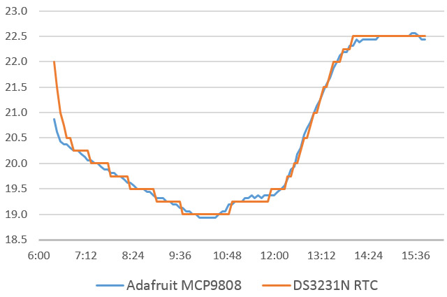
Most of the time you will see a small offset between the RTC and the reference sensor, and you can correct that to three nines with a linear from the calibration dataset. (a typical example: y = 1.0022x + 0.0646, R² = 0.9996) Another thing I’ve noticed is that the RTC’s temp. register starts to diverge from my reference sensors above 50°C. So the DS3231 should probably only be used to discipline temp. accuracy across the same 0°C to 40°C range specified for the ±2ppm rating.
After the initial calibrations are done, you can correct drift in the frequency-delta temperatures by comparing them to the RTC’s temperature register. The only fly in the ointment is that the RTC record is so crude that direct adjustments based on it have the potential to put ugly stair-step transitions all over the place.
Drift correction with an Leaky integrator
Drift correction is necessarily a long game, so I’m not really worried about individual readings; just the overall trend. Tracking this requires more readings than you would use in a typical moving-average. In addition, the 328 doesn’t have much computational horsepower, and it’s easy for numbers extending past the third decimal place to over-run the memory. One solution to those problems is the leaky integrator:
//I pre-load filter variables in setup for 25°C, but that is not necessary
uint32_t rtcfiltSum = 800000;    // the previous reading "memory" variable (32*25000)
uint32_t rtcFiltered= 25000;     // equivalent to a temp of 25C
int filterShift = 5;             // equivalent of dividing new readings by 32
float tempFloat; uint16_t newValue;

//bit shifting only works with positive integer values (so no negative temps!)
//so you have to convert the decimal-float temperature readings
tempFloat=TEMP_degC*1000;  //preserves three decimal places from the RTC temp. reading
newValue=(uint32_t)tempFloat;
// this is the filter itself - save rtcFiltered in the log file for drift correction
rtcfiltSum += (newValue - (rtcfiltSum >> filterShift));
rtcFiltered =(rtcfiltSum >> filterShift);
That is an hefty amount of filtering, so the value in rtcFiltered will lag behind the current temp reading by several hours. However using a shift of 5 means that each new data from the RTC’s temp register only adds 1/32 of that to the final filtered value. Even if the RTC takes one of it’s gigantic 0.25°C steps, the filtered value changes by only 0.25/32 = 0.0078°C. This transmogrifies the crunchy RTC record into one with a resolution comparable the data we are deriving from the frequency delta. Then the de-trending can be done without harming the small details in the high resolution record. I could probably change that to shift=4 for faster response as only 1/2 of the resulting 0.0156 steps would typically show up in the record on average.
So the method is basically:
1) Create an IIR low-pass version of RTC’s temperature register.
2) Use the same leaky integrator on the frequency based temperature, which is calculated from the calibration data’s fit equation.
3) Compare those two heavily filtered numbers to create a rolling adjustment factor that you apply to the frequency based temperature data. Because you are only trying to compare long term behavior, you want these to be ridiculously heavy filters (ie shift 5 or 6) which you would never use in normal sensor filtering applications.
A typical 15 minute sampling interval only generates 96 readings per day, so this leaky integrator approach would take 8 hours to adapt to large changes in the offset. So it won’t do a thing to help you with short term hysteresis in environments that see large daily temperature fluctuations. However, it would gracefully handle the line regulation problem, and it will respond to aging offsets that change direction half way through a long deployment. Many sensors suffer from drift issues like this, and its easy to see how this correction method could be applied to those situations if you could define a temperature relationship.
Of course this begs the question of why Maxim didn’t make that temperature record available at a higher resolution in the first place; especially when you see all those unused bits in the register: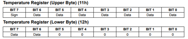
I suspect the design engineers had higher resolution output in the original plans, but it was pulled when some bean counter pointed out that doing so would cannibalize existing sensor sales – especially the highly profitable DS18b20s. If that is the case, it certainly wouldn’t be the first time a company disabled capabilities in a design to protect other product lines.
When things go squirrelly
I’ve been talking about the resonator/clock as though it was an isolated system, but this method is really a test of all the components on the board, and sometimes those combinations produce some pretty weird behavior. For example: The Rocket Scream Mini Ultra has long been one of my favorite Arduino compatible boards, and I’ve use it in many different logger builds because of it’s efficient MCP1700 regulator. But it doesn’t seem to work with this two-clock method because of a spectacular discontinuity at around 23°C: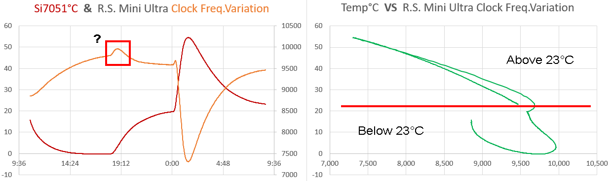
Any response curve that produces non-unique solutions like that will make it impossible to do a simple regression curve-fit. The 800ST ceramic resonator on the Mini Ultra I used for this test looks quite different from the metal-can style one on the cheaper clone board, and it’s larger size has me wondering if there was some kind of compensation circuitry that was suffering from really bad hysteresis. Of course, there is always the chance I made calculation error somewhere…but if so I still haven’t found it, and the same code was running on both boards. The fact that the temp-frequency graph showed an inverse relationship also has me scratching my head.
Where to go from here…
Every board/RTC combination will have to be calibrated, which is a bit of a pain if you’re not doing week long burn tests like we do. But the thing that really amuses me about this approach is that the potential resolution is inversely proportional to the quality of the components you are using. Rantwijk found a temp-co of less than +0.97 Hz / °C on the Duemilanove so the method has access to 100x more resolution on a Pro Mini. If you’ve got a Genuino with a quartz oscillator, it’s probably not worth your time to even try.

One problem with driving the dry-box down to sub-zero temps is that the freezer’s compressor cycle will muck up the data if you don’t have enough thermal mass. If you live in a suitable climate, outdoor temps give you better results, with the added benefit that your spouse won’t gripe that they can’t find the chicken to make dinner behind “all that crap” you’ve stuffed into the ACSF. (Arctic Conditions Simulation Facility)
Unless . . . uhhhh . . . doesn’t the 328P’s internal clock use an RC circuit with even more variation than the external ceramic resonators? If memory serves, Atmel suggests calibration to wrangle that puppy down from the ±10% factory defaults to ±1% over the -40 to 85 °C operating range. (see AVR4013: picoPower Basics) For an 8 MHz system, that works out to a delta of more than 600 ticks per degree. If you used Nick’s code to count with the 328’s internal oscillator, you could reach ±0.001°C with this two-clock method. That’s approaching what you’d get from an RTD, and all you need is a $1 DS3231SN module from eBay. Since you’d be dealing with parts inside the 328, you likely won’t have the kind of board to board variation I ran into with the Mini Ultra.
To read ambient temps, you would have to take the count right after waking from about 10 minutes of sleep, so the chip was not reacting to it’s own internal heating. And I suspect reconciling the accuracy of those readings could involve more calibration-penance than any self-respecting maker should ever have to pay. But it is just sitting there, waiting to be done by someone willing to set some fuses…and that voice whispering in your ear right now is just good honest intellectual curiosity. No sin in that. Right?
After these shenanigans, I propose we update that old saying:
“A man with one watch knows what time it is. A man with two watches is never sure.”
with the postscript: “But at least he can measure the temperature to ±0.01°C, provided one of those clocks is a 99¢ piece of junk from eBay.” 🙂
Addendum: 2018-03-19:
Just found an interesting document from the fluke archive describing the drift on an RTD sensor described as 90-day accuracy: 8520A/PRT precision temperature system (see graph on page 1) Whats interesting is that those curves seem to have a period of accelerated drift, and then flatten out again.
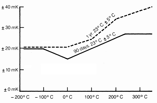 Exposure to high temperatures affects all resistors (which RTDs & thermistors are). Prolonged exposure to temperatures over ~100°C will cause a higher drift rate compared to lower temperatures. Our loggers are usually out on deployment for at least a year… I’d be kidding myself to think I could constrain drift to anything near this RTD’s performance with the RTC oscillator.
Addendum: 2019-02-07:
Just found another interesting “no parts” method to measure ambient temperature with an Arduino over at AvrFreaks:
“An alternative low pin/parts count method could be to use the temperature dependence of the output impedance at the AREF pin. If you have the typical external capacitor there, the time it takes get the reference stable when switching from high (VCC) to low Ref (internal 2,5 V) should depend on temperature.”
I run into Aref cap settling times frequently – often on the order of 10ms when going from the rail down to the internal 1.1v ref . Timing that would be a matter of reading the rail voltage against the bandgap until the number stabilizes after the change. Easy Peasy!
Addendum: 2024-10-22:
And speaking of time related methods, we finally got serous about synchronizing the RTCs for multi-unit deployments: Our logger clocks are sync’d to the leading edge of a GPS time-pulse and the Aging register is tuned to reduce drift.

This is neat… and, I have to disagree a little with the coders; if they’re complaining about the legacy aspect of HW and SW, perhaps they’re forgetting that *everything* is legacy-based. But on a more practical level, one perhaps your spouse should chime in on, how much temperature resolution do you need?
I still haven’t deployed, but I’m getting close, and often look at the temperature curves from the RTC3231, a DS18B20, and the higher resolution temperatures returned by BMP280/BME280. These are all (within a linear constant offset) in agreement, but the time behavior often isn’t: the DS18B20 has remarkably small thermal lag (considering in a waterproof housing it *looks* like it has some thermal mass), and often the BMP280’s will have different response even though they are sitting on the same breadboard.
What type of signals are “real” here, in the research? Can you “see” a dive in progress from the thermal data? I’m still not sure what, if anything, I’ll see in a cave (the DS18B20 is for water temperature, air temperature will be from the BMP280).
While the story is true, that last comment about taking me out of the gene pool was made with a smile and a laugh. He wasn’t actually bothered by the idea of leveraging a fault in hardware, but I have run into plenty of engineers that would be.
WRT the question of useful temp resolution: I asked Trish and she pointed out that the sensitivity you need for research depends on the annual range of the local climate. So the work in tropical areas usually sees a total annual range of less than 1°C in ground water temps because they such an incredibly stable climate. So the DS18b20’s with only 0.0625° are really just at the edge of the useful range in those environments, and we often find ourselves wishing the data went to 0.01°C : that’s really become our research benchmark for temp sensors (with an accuracy of at least +-0.25° or better). However at a location in the U.S or Canada, that sees enough annual climate variation to see real snow in winter, the DS18 could be more than sensitive enough, so long as you have calibrated them.
WRT dives in progress – yes you can definitely see the thermal profile with a quick sensor like the DS18, provided it is in direct contact with the water, but I’m switching over now to thermistors because they have smaller thermal mass, which gives you almost instant response. But I will have to put them into the metal enclosures to protect them from pressure. The RTC trick I described in this paper is really just for measuring ambient inside the housings, and they are surrounded by so much thermal mass ( the housing, batteries, etc) that temp spikes from bursts of barometric-forced airflow get rounded out of existence. Even so the RTC temp data is so easy to read, I just include it as a backup. I’m still tweaking the code for this two clock method, and when I’m sure the leaky filter has been tuned to the correct lag/resolution I will post a link to the code on github. Anything you can do to get more data without adding hardware is usually a good idea. So my advice is to record temp data from all the sensors you’ve got that are capable of it.
I would love to hear about your progress with the BMP280’s, most especially about how long they manage to run. Every electronic R.H. sensor we’ve tried to date has failed within a month (usually within a week) because they don’t recover on their own from condensing conditions, which are very common in tropical caves. I hope you get more data than that.
“…So the work in tropical areas usually sees a total annual range of less than 1°C in ground water temps because they such an incredibly stable climate…”
Yes, I’m not sure what if anything I’ll get in temperature – surface temperature variation is much greater in KY, but how far that thermal pulse penetrates is… well, unknown. In entrance areas I expect to see some variation, but I’m not sure how close I’ll have to get (and for that matter the entrance we’ll be using is an artificial one, which we normally keep a lid on to reduce surface impacts… still, there’s a natural entrance out there somewhere becasue there were bats before we dug the entrance open). The water temperature should be interesting (and, I hope, captured by the DS18B20’s). The first run will likely be uncalibrated as I’m just curious at the variation, not absolute temperature yet. There’s anecdotal observations that suggest some areas take rapid enough surface runoff to produce a thermal signal, but… we’ll see what the data shows.
“…I would love to hear about your progress with the BMP280’s, most especially about how long they manage to run…”
The BMP/BME280’s were selected as a small, very cheap high-resolution pressure sensor… as a by-product, they can get the ambient air temperature. And because I really want two on each logger (one for ambient air pressure, one for pressure in a plastic tube with the open end on the bottom of the pool or stream), making one of them a BME280 with RH gives me off-the-shelf I2C addresses that don’t collide, while using the same code to read them. Like you said, it’s nice when you can gather more data without any change in the HW.
After this deployment I’ll probably play with adding more EEPROM – I have thoughts to streaming 10s to 30s time resolution data into a circular buffer, only writing that high time resolution data to the SD card if “interesting” events occur (flood pulses). I’m already planning on having the time resolution scale down as the battery voltage drops, so that I can stretch the record (even if at lower resolution.
If you are using a circular buffer, then base your builds on the Moteino Mega. The pin-out is a bit different wrt SPI & I2C, but it’s not too hard to figure out how to connect the parts for a basic logger build. The 1284 has 16KB RAM (compared to just 2KB on the atmega328p) which gives you a much longer buffer to look at before you decide to start saving, and once you have the board definition installed in the IDE the code is pretty much the same. If you are using the R.Scream sleep library, make sure you have the updated one which supports the 1284.