
Here I’ve added a the 5110 LCD to a logger recording data from a BME280 & Tipping Bucket Rain gauge. If the BME survives in our field environment, this will become a standard configuration for our climate stations. I’m not holding my breath though, as we’ve tested half a dozen RH sensors so far and none of them have gone the distance in high humidity environments that occasionally go condensing.
This year I want to tackle some projects that need live data out, so I’ve been sifting through the many display options available for Arduino. Unlike flashier projects, my goal was to find one that I could add to existing logger builds without sacrificing too much of the multi-year lifespan I had worked so hard to achieve. The low power winner by a fair margin was the Nokia 5110 Liquid-crystal Display which you can pick up for around $2 from the usual sources. With the back-light off these displays pull between 100-400 μA, depending on the number of pixels turned on.
This screen uses a PCD8544 controller and the SPI protocol. It will tolerate 5V, but it works best at 3.3V, which is perfect when you are driving it from an 8mhz ProMini. Each pixel on the display is represented by a single bit in the PCD8544’s RAM. Each byte in RAM correlates to a vertical column of 8 pixels. The X coordinate works on a per-pixel basis, and accepts values between 0 and 83. The Y coordinate accepts values of 0 – 5 which on this 48 pixel high screen, corresponds to 6 “rows of bytes” in the controller’s RAM. So bitmaps can only be displayed on a per row (& column) basis. The display is quite sluggish compared to competitors like the 0.96 I2C monochrome OLED and you have to handle any processing overhead on the Arduino.
Most hookup guides assume that you can spare six control lines to run the display, which is not the case when your logger already has three indicator LEDs, I2c devices, one wire sensors and a couple of voltage dividers on the go. However if you are willing to add a few resistors and occasionally toggle the power, you can bring that down to three wires and a power pin.
So many libraries, so little optimization…
This screen’s been around for a very long time, so there’s are a huge number of easy to use, highly functional libraries for Arduino. But they tend to focus on things like speed or endless font options which are not important for most data logging applications. And these libs assume your project can afford to lose up to ⅓ of the available program & variable memory just driving the display. Most also require the hardware SPI lines, but our project needs those for SD cards, which are finicky enough without some pokey LCD gumming up the works: the 5110 maxes out at 4mbps, and this slows the bus significantly .
Those fat libs were non-starters for our project, and I had almost given up on this display when I found Ilett’s Ardutorial offering a bare-bones method more suitable for our resource limited data loggers. If you haven’t discovered Julians YouTube channel yet then you are in for a treat because if Andreas Spiess is the maker worlds answer to Werner Herzog, then Julian is surely their equivalent to Bob Ross. I don’t know if he’s growing “Happy little trees” with his DIY hydroponics, but I can say that the gentle timbre of his “Gooood morning all” reduces stress faster than a warm cup of Tea. And his “Arduino sandwiches” are brilliant examples of minimalist build technique.
Driving the Nokia 5110 with shiftout
Everything I’m presenting here builds on his tutorials, so grab a mug and give ’em a watch:
Tutorial #1 – Connecting and Initial Programming
Tutorial #2 – Getting Text on the Display
Tutorial #3 – Live Numerical Data
This software SPI method (originally from arduino.cc?) requires no library at all, and shiftout commands work with any combination of digital pins; saving those hardware SPI lines for more important jobs.
Initial setup is explained in video #1 using two functions
void LcdInit(void)
{
digitalWrite(RST, LOW);            // not needed with pin powering!
digitalWrite(RST, HIGH);           // see below for details
LcdWriteCmd(0x21);                 // extended commands
LcdWriteCmd(0xB8);                 // set Vop(contrast) // you may need to tweak
LcdWriteCmd(0x04);                 // set temp coefficient
LcdWriteCmd(0x14);                 // bias mode 1:40 // you may need to tweak this
LcdWriteCmd(0x20);                 // basic commands
LcdWriteCmd(0x0C);                 // normal video
for(int i=0; i<504; i++) LcdWriteData(0x00);  // clear the sceen
}
void LcdWriteCmd(byte cmd)
{
digitalWrite(DCmodeSelect, LOW);    // low for commands, high for data
digitalWrite(ChipEnable, LOW);      // not need with pin-power
shiftOut(DataIN, SerialCLK, MSBFIRST, cmd);  // transmit serial data
digitalWrite(ChipEnable, HIGH);     // not need with pin-power
}
After that you need is a function to position the cursor and a font stored in a byte array (in this example called ASCII[][5])
void LcdXY(int x, int y)
{
LcdWriteCmd(0x80 | x);              // Column
LcdWriteCmd(0x40 | y);              // Row
}
Then three short cascading functions let you send a string of ascii characters to the display:
void LcdWriteString(char *characters)
{
while(*characters) LcdWriteCharacter(*characters++);
}
void LcdWriteCharacter(char character)
{
for(int i=0; i<5; i++){
LcdWriteData(pgm_read_byte(&ASCII[character - 0x20][i]));
}
LcdWriteData(0x00);            //one row of spacer pixels between characters
}
void LcdWriteData(byte dat)
{
digitalWrite(DCmodeSelect, HIGH);    // High for data
digitalWrite(ChipEnable, LOW);
shiftOut(DataIN, SerialCLK, MSBFIRST, dat);  // transmit serial data
digitalWrite(ChipEnable, HIGH);
}
Julians original implementation included a 500 byte 5×7 font.h file (which you can find at several locations) and I’ve rolled that font array into some code based on his work and posted it to the Cave Pearl Project’s repo . You will find lots of other examples based on the shiftout method on Github, but for some reason many people insist in retooling that tiny bit of code into, you guessed it, even more libraries…
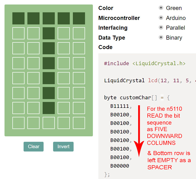 You’ll also find plenty of other drop-in font definitions with Google, but for small 5×7’s, it doesn’t take that long to roll your own by clicking the boxes in an online font creator. and then copying the byte pattern into a bin-hex converter. This also gives you the option of creating custom icons by using a non-standard bitmap for some of the less frequently used ascii characters. Keep in mind that you don’t need to store the entire alphabet if you are only sending a few letters to the screen (like ‘T+P’ or ‘RH%’, etc …) extracting only the letters you need to a reduced font array could save a lot of memory.
So your reduced font array could look something like this:
const byte ASCII[][5] =
{
{0x7f, 0x09, 0x19, 0x29, 0x46}  // 52 R
,{0x7f, 0x08, 0x08, 0x08, 0x7f} // 48 H
,{0x23, 0x13, 0x08, 0x64, 0x62} // 25 %
,{0x01, 0x01, 0x7f, 0x01, 0x01} // 54 T
,{0x08, 0x08, 0x3e, 0x08, 0x08} // 2b +
,{0x7f, 0x09, 0x09, 0x09, 0x06} // 50 P
};
If you do that you’ll need to send text to the screen character-by-character because the ASCII based [character – 0x20] calculation won’t work any more.
I tweaked Julians code in a couple of important ways. First, I added PROGMEM to move the font(s) into the program memory space. Second, I added a method to print large numbers to the screen by repeating the same WriteString->WriteCharacter->WriteData pattern two times: once for the “upper half” of the numbers, and then again for the “lower half” of the numbers after re-positioning the cursor to the next line.
To make this limited large-number font I first composed a black & white bitmap for each number with a graphic editor, and then loaded that .bmp file into the LCD assistant program as described in this instructables tutorial. I started with a bitmap that was 11 pixels wide, by 16 pixels high (though you can use any arbitrary size you want – just remember to leave the blank spacer row at the bottom) and for this two-pass ‘sliced-letters’ method I set vertical & little endian encoding in LCD assistant. I then put the top 11 bytes in the Big11x16numberTops[] array & the lower 11 bytes for each number in the Big11x16numberBottoms[] array.
It takes two passes to print each large number to the screen:
LcdXY (0,2);              //top half of the double-size numbers
LcdWriteBigStringTops(dtostrf(voltage,5,2,string));
LcdXY (0,3);              //bottom half of the numbers
LcdWriteBigStringBottoms(dtostrf(voltage,5,2,string));
And some slightly modified functions that refer to the corresponding number-font array:
void LcdWriteBigStringTops(char *characters)
{
while(*characters) LcdWriteBigCharacterTops(*characters++);
}
void LcdLcdWriteBigCharacterTops(char character)
{
for(int i=0; i<11; i++){
if((character - 0x2d)>=0){
LcdWriteData(pgm_read_byte(&Big11x16numberTops[character - 0x2d][i]));
}
}
LcdWriteData(0x00);  //one row of spacer pixels inserted between characters
}
Those number printing functions could be eliminated with better use of pointers, but I liked having the readability afforded by a few extra lines of code.
Reducing the number of control lines
The stuff I posted on Github assumes you are using a standard 6-pin arrangement shown in most Nokia 5110 hookup guides you will find on the web. But once I had that wrangled, I realized that it would be possible to reduce the number pins needed to drive the display. You will have to tweak that default example by commenting out the RS & CS commands if you implement the pin-power changes I’m suggesting here…
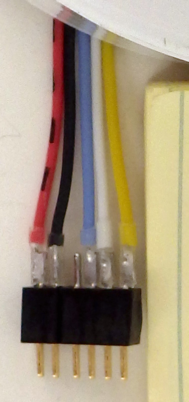
I use Deans micro-plugs for multi-wire applications like this. The unused pin here is the normal Vcc, with the A0 pin-power supply indicated with a dash on the red line.
The shiftout method can be used with any pins you want, and most of my builds have A0-A3 available. With those dedicated wires the PCD8544’s chip select (CS) line can be connected to GND telling the screen that it’s always the selected device. This would be bad if it was connected to the hardware SPI lines shared with the SD card, but since we are using re-purposed anlaog lines, there is no conflict. One minor drawback is that since we are now using all the analog lines (I use A6 & A7 too) we can’t read a floating pin for RandomSeed().
Getting rid of the RESET line is a little trickier. The data sheet says that the RS line must be low while power stabilizes and should then be pulled high within 100ms of power on. Several people create an auto-reset situation by connecting the screens reset to the Arduino’s reset line. Others make the low-high transition with an RC network across the supply for a delayed rising signal. This can even be driven by the DC line (which is low in command mode and high in data mode)
But I had something else in mind, since I wanted to power the entire display from a digital pin because the power draw with the display off is still about 70uA. This accumulates into a significant amount of wasted power over a multi-year deployment.
Reducing Back-light Current
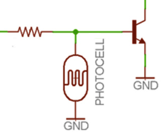
OR … a photocell divider embedded in that clear epoxy would let you enable the backlight dynamically – with the appropriate mosfet for the connection type.
If you use the back-light in the default configuration, the screen can potentially draw up to 80mA (4 white LEDs at 20mA each). The back-light pin is usually connected to a transistor, so you can PWM all 4 LEDs at once for variable lighting control, but the peak currents are still too high for direct pin-powering unless you add some kind of series resistor. A 10k pot gives you a simpler method to adjust the screen brightness, but I found that a 3k3 series resistor brought the total display current down to ~1mA with decent readability ( & blue LEDs are brighter than white). Adding an in-line slide switch provides a way to completely disable the back-light for long deployments. With the entire display safely below Arduino’s pin-current limit, you can then power it by writing a driver pin high or low in output mode.
#define n5110PowerPin  A0          // power the 5110 screen from pin A0 (RED)
#define n5110modeSelect A1         // 6.1.9 D/C: mode select (BLUE)
#define n5110SData A2              // 6.1.7 SDIN: serial data line (WHITE)
#define n5110SCLK A3 ;             // 6.1.8 SCLK: serial clock line (YELLOW)
// lines not needed any more:
// #define n5110RST  Now -> 4.7k to power A0
// #define n5110ChipEnable  Now -> GND
This gives you a way to perform a hard reset any time you want provided you tie the screens RS line to that switched power with a 4k7 pullup resistor, and re-run the initialization sequence after restoring power.
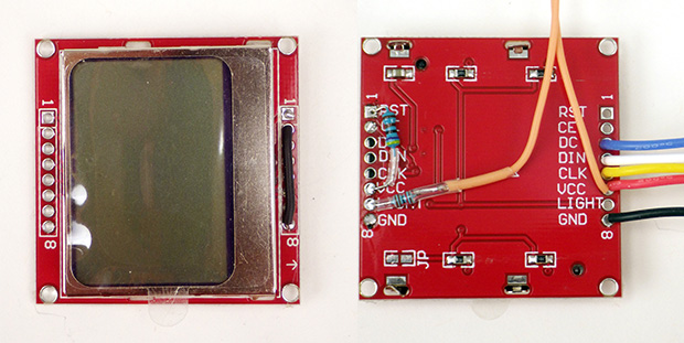
Boards with pin vias on both sides make it easier to add the RST & CE connections. The orange wires shown here thread through the housing to a slide switch which disables the backlight connection for surface deployments. This example connects power to the backlight, but with other screens you might have to connect BACKLIGHT to GND.
Enabling the screen now looks like this in setup:
pinMode(n5110PowerPin, OUTPUT);
digitalWrite(n5110PowerPin, HIGH);
pinMode(n5110modeSelect, OUTPUT);
pinMode(n5110SData, OUTPUT);
pinMode(n5110SCLK, OUTPUT);
LcdInit(); // shiftout takes control of Mode, Data & SCLK lines at this point
To turn off the screen you pull all the control lines low:
digitalWrite(n5110PowerPin, LOW);
digitalWrite(n5110modeSelect, LOW);
digitalWrite(n5110SData, LOW);
digitalWrite(n5110SCLK, LOW);
All four control lines must be brought low when you de-power the display or you will get a 13mA leak current through the controller after vcc goes low. Only the power pin needs to be driven high to start the screen later in the main loop, but don’t forget to run the init each time you power up.
My tests so far have shown reliable operation of pin-powered 5110’s through more than 8000 ‘long-sleep’ power cycles. In applications where I want to display data on the screen on for long periods of time, I still depower the screen during the new sensor readings. This lets me know when the logger is capturing data and forces a periodic re-synch with the bus. I don’t know how long these displays would run continuously without that step, but I’m sure the coms would eventually go AWOL without some kind of regular reset.
Potting the Nokia 5110 display
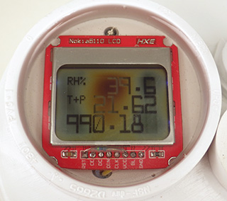
Contraction of the epoxy created pressure burns on the LCD when I did a single large pour to pot the screen.
No screen is much use on our project unless it can withstand some bumping around in the real world, and ideally we want one that is dive-able. For several years my go-to solution has been to pot surface mounted LED’s and sensors in Loctite E30CL. I like this epoxy because the slow cure usually sets clear because bubbles have time to rise to the surface without a vacuum treatment. My first attempts looked great the night of the pour, but I got a nasty surprise the following morning. You see I usually mount sensors in small ½-1 inch wells, but the 5110 required a ring more than 2” in diameter. The contraction of the epoxy in this 10mm deep well caused pressure marks on the edges of the screen, and a significant brown spot in the center of the display where the text became inverted.
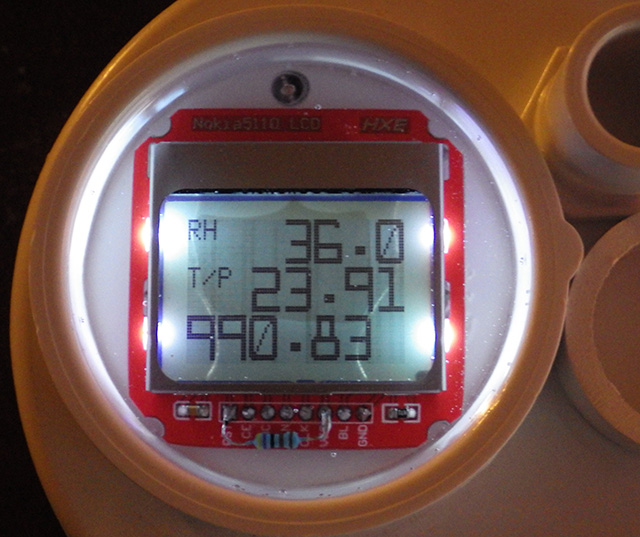
Successive small pours worked better. Here the back-light reflects off of the edges of the epoxy that seeped under the screen before it finished setting. The display in this photo has a 3k3 series resistor in the backlight circuit.
The next attempt was much more successful, as I built up the epoxy a few mm at a time like the layers of an onion. As each layer hardened, it protected the screen from the contraction of the subsequent layers above. The trick was to bring the first pour to the base of the pcb, and the second pour to “just barely” cover the surface of the screen. The epoxy penetrates about 1/3 of the way into the display housing but this does not interfere with readability as those edges are invisible under natural lighting conditions. That epoxy is actually under the LCD, in the air gap between the transparent glass LCD sandwich and the white reflector plastic which holds the thin LCD in place between the metal rim and the PCB. I’ll try future pours at different angles to see if that lets the space under the LCD fill completely. Looking at the epoxy penetration, it’s clear that the black edges in pour #1 were places where the LCD was compressed on both sides, and the brown discoloration was from pressure on top with no support below.
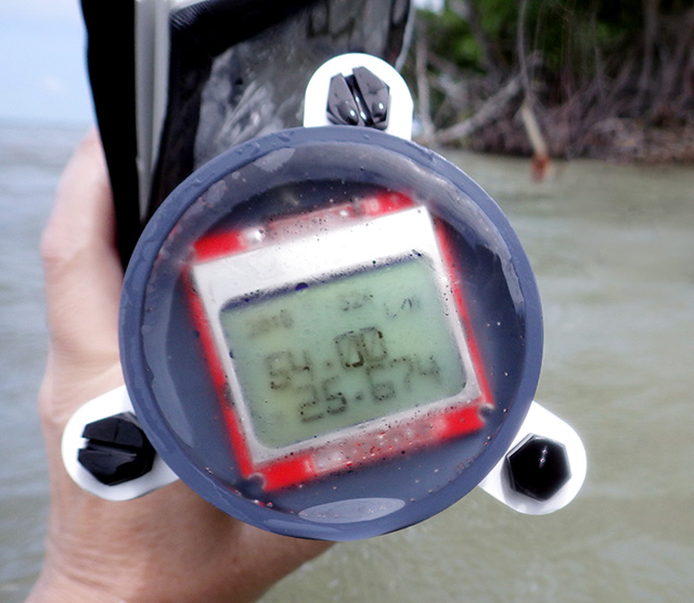
Seawater caused severe fogging of the potting epoxy after only three days in service. Originally a concession to my aging eyes, the large fonts really saved our bacon when this reaction occurred.
The results for the second batch looked good and the screens worked beautifully with full marine submersion for about two days. Then some kind of chemical reaction with the sea-water started fogging the epoxy, and by day three I was glad I’d created the large number fonts because the 5×7’s were completely unreadable. Once we were back home, a bit of elbow grease & 800 grit removed the foggy surface rind, and a layer of conformal coating restored clarity. I think my next builds will add the coating to the epoxy surface at the start.
I also noted some screen discoloration from pressure at about 3m depth, indicating that even a thick layer of epoxy bows too much for a deeper deployment. I’ve ordered some 1/4“ plexiglass disks to provide a surface with a bit more chemical resistance, and will post an update on how that works after the next fieldwork trip. I’m hoping that provides a bit more pressure protection too, but the shore hardness of the epoxy is 85, and PMMA (plexiglass) is only a few steps above that at 90. I might try polycarbonate as well.
Other Fun stuff:
There is so much more to explore with this screen, including live graphing libraries, and display controls so I expect it will keep me amused for a while since I can add it to any of the current logger builds. Several are out in the wild now for long term tests, and I’m currently working on a script to move those fonts (and a few other things) into the 328p’s internal eeprom. If all goes well I’ll release that ultra low memory footprint version of the code shortly.
Cheers for now.
Addendum 2018-08-24
After several builds using the this LCD screen I finally got around to storing those font arrays in the Arduino’s internal EEprom. Works a treat, and frees a good chunk of PROGMEM space with very little change to the core functions. With fonts in EEprom, the remaining Nokia 5110 functions compile to a little over 400 bytes of program storage and 10 bytes of dynamic. (not counting EEprom.h) And that’s with three copies of the output functions because of the simple 2-pass method I’m using to display the large numbers. A small price to pay for live data output on our loggers!
Addendum 2018-10-17
 Because of that pressure problem with the 5110 I decided to try out the 0.96″ OLED screens which sell for about $3 on eBay. When the first batch arrived I was pleasantly surprised by how well they stood up to pressure on their surface. Then I found the SPI version of the SSD1306 OLED can be driven by essentially the same code as the PCD8544 (with the exception of the init & XY functions which are specific to each controller).
Adding the SSD1306 OLED Screen to an Arduino Logger (without a library)
I’m connecting the OLED with the same analog line connections used for the Nokia, but I’ve added a delayed-high RC bridge because the OLED is pickier about the reset input than the Nokias. In hindsight a similar method is probably a good idea for the Nokia screens as well, though you might need to experiment a bit with the resistor/cap values to get the timing right.
Addendum 2020-11-15:
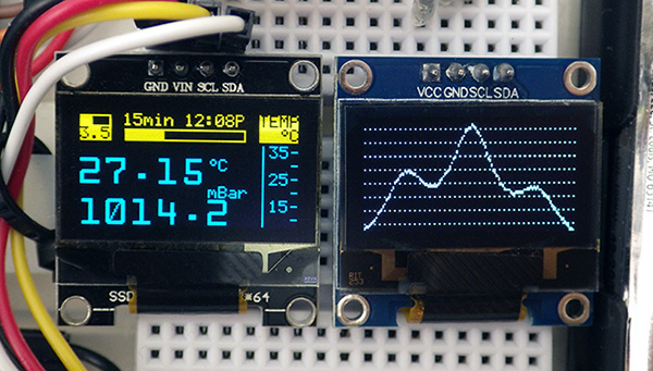
Two I2C 0.96″ OLED displays make a highly useful addition to the basic three module logger
I finally got around to adapting this eeprom/fonts method for use with I2C displays:

You just keep finding new ways for me to spend my money and time (thank you!)… and all this after I built in a bunch of a three-color flashing codes so I can figure out what’s going on :).
For pressure resistance I would think the clear window approach would be workable. That’s not a large flat area to support pressure against. With PVC standoffs under the window to hold an air gap, and epoxy sealing the entire cell, I think it might make a good observing window. I’m thinking of doing something similar (optical window, not display) to get a measure of water turbidity during storm events.
Note that with the CDS photocell you have a sealed “switch”: put a flap or door over the display and CDS cell to protect it. If the CDS cell detects light, somebody just have pulled back the flap and is looking at the display, so *only* then does the logger need to power the display at all. I’m toying with putting CDS cells in my builds to function as ambient light detection (not normally needed, but… might be a fun way to track caver traffic in some areas) and also user switches (with no moving parts, just changing light levels).
Never underestimate the importance of indicator LEDs: https://globalnews.ca/news/4218174/astronaut-forgets-sd-card/
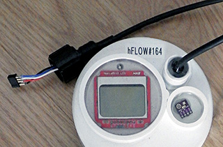
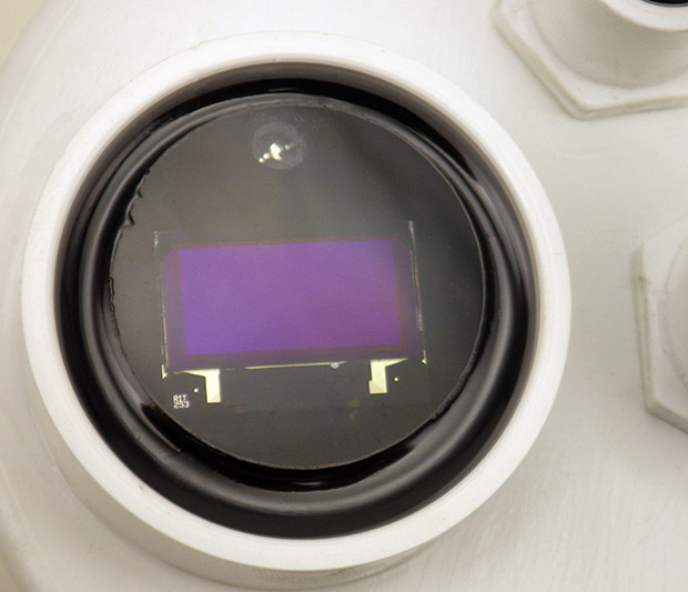
I will always put a 3-color LED & use the flash codes on my builds even if they have a screen. The screen in the grey cap (shown at the bottom of the post) was displaying output from several sensors including a rotary flow sensor, and I had it pip the LED every time an interrupt was generated, and this ended up being very important because all the gunk in the water would jam the rotor. Visibility was effectively zero at the business end, so the LED flashing at the display gave the surface operator a sense of “is this thing operating normally” by watching the pip frequency BEFORE the reading data was displayed on the LCD screen. So the effort to make good flash codes was not wasted..
Eventually I want to go deep with these screens, and drawback of LCD screens is that they are actually less readable if there is enough ambient light and the back-light comes on. So if I flash the screen with my dive light (located on my hands/helmet) I’d like the back-light LEDs to turn off automatically so the two light sources are not fighting with each other.
If you find a good source for those optical windows please pass on the info. I’ve a few ideas that need them, but have not had time to sift through all those data sheets describing how each window material filters the frequencies. When you add that to the weird response curve of the light sensors you realize that’s where the real work is for things like PAR sensing.
Agreed that the flash codes still have a place – right now on start up the logger checks each sensor and gives me a code telling me if it detected a working sensor or not for example, as well as checking the SD card and all the rest. So I’ll continue to use them, but I do like this for some things.
How much do you think this will hit your battery life?
With respect to the windows, agreed, the spectral response will be something to consider… but it already is with all the different types of light sensors. So I look at this as a system-level calibration problem more than looking at how the window will further modify an already odd spectral response. For calibrated data, important… for relative change, not as important, and I’m still very much behind you on the “requires certified calibration” curve.
For windows (the easy kind), they do make clear PVC and acrylic pipe that fits standard plumbing sizes. It’s not as cheap as the “cheap stuff”… but you don’t need much of it, and it works very well with a DIY approach of “what can I order on-line?”
With pin-powering, the display draws no current at all during the sleep interval between samples.
I haven’t done a really detailed analysis of the start-init-write-display sequence yet, but with no back light, and the main logger sleeping again as soon as the numbers are on the screen, I’m budgeting about 30 milliampSeconds per 30-second display event. In that range a typical day with a 15 minute sampling intervals would cost about 2,880 mAs. Roughly speaking, that would add about 10% to the daily power consumption of a logger sleeping at 0.25mA. But I’m being very conservative here, and its probably much better than that…
Just thinking some more about the CdS switch idea… I like it! I’m so used to reed switch interrupts that I was planning on using them embedded in epoxy or for switches inside the housing (with a magnet), but I always have a light with me caving & cave diving so that would be a better option – one less thing to remember…
I’ve been potting my indicator led’s in 1/2 NPT male top connectors for ages now, but there’s always the one on the other end of the housing that could act as the potting space for this optical switch. And I could cover it with a 1/2″ NPT cap while the unit was on the surface, so it did not trigger the entire time. If I set it up as a pin change int, I’d want to trigger on the falling edge, and a little cap could debounce…. hmmmmmm
Pingback: Using a Nokia 5110 LCD with only 3 control lines and pin-power for low current sleeping – Old Wire Head