
The slightest breeze makes glass bead thermistors jitterbug like crazy, so put them inside something with a decent amount of thermal inertia before you do any oversampling experiments. Otherwise thermal noise could make it look like your dithering is sufficient for oversampling, when it’s not.
While I was figuring out how to read thermistors with our Arduino based data loggers, I came across claims that you can improve the resolution of any Analog-to-Digital converter with a technique called oversampling & decimation. I had already doubled the number of ADC bits covering my target temperature range by powering a thermistor divider from the rails and using the internal 1.1v as the analog reference. And my gut feeling was that aref-based ADC bits were somehow better than any I could synthesize, but I was still curious to see if I could add over-sampled bits to the ones obtained with the bandgap trick.
At first bounce, the method appeared to be incredibly simple, to get n extra bits of resolution, you need to read the ADC four to the power of n times. Generally you have to add three extra bits (43= 128 samples) to see approximately an order of magnitude improvement in your real world resolution. With thermistor dividers, you typically get about 0.1°C from the default ADC readings, and 128 samples bumps that to 0.012°C. Taking (46= 4096) samples would bump that up to ~0.0015°C which, as the saying goes, is good enough for government work…
I usually over-sample one power more than needed for my target resolution, so I’d use for four extra bits to be sure of that order of magnitude improvement, which requires the sum of 44= 256 readings:
for (int k = 0; k< 255; k++) {
extraBits = extraBits +analogRead(AnalogInputPin);
}
which is then decimated by bit shifting right by n positions:
This combination lets you infer the sub-LSB information provided there is enough random noise in the signal for the lowest ADC bits to toggle up and down while you gather those readings. But without the noise, all of the original ADC readings are the same, and the oversampling technique does not work. To show you what that kind of failure looks like, here is oversampling & decimation being done over 4096 readings with no noise or dither signal applied to a 10k NTC thermistor divider read with 1.1v aref:

These are readings from a 10k NTC thermistor divider, and I’ve offset these records from each other by 0.1° for easier comparison. The one-shot ADC readings of the thermistor bridge in purple are converted to °C, as are 4096 sample readings at the default 125kHz(ps64) in grey, 250kHz(ps32) in orange and 500kHz (ps16) in green. With such a large number of samples, the averaging produces some smoothing whenever the raw ADC readings near a transition point, but if you see “rounded stair steps” like this then oversampling is not working properly – the curves shown above are all FAILURES.
Some microprocessors have enough jitter in their readings to use oversampling technique with the natural toggling of the least significant bit. A few brave souls have even tried to improve the AVR’s crude internal temperature sensor with the technique. But most of the time, there is not enough naturally occurring noise, and you need to add a synthetic dithering signal to force those LSB’s to toggle. This is mentioned from time to time in the forums, with a number of references to AVR121: Enhancing ADC resolution by oversampling, but I found frustratingly few implementations using an Arduino that were described in enough detail for me to replicate them. Most of the technical docs were focused on audio applications, and I was quickly buried under thick mathematical treatments warning me not to interpret the Effective Number of Bits (ENOB) as Effective Resolution (what?), and describing a host of other quid pro quos like signal synchrony.

This is Qwerty’s original dither circuit from the freetronics forum. If you are using an UNO, this works well. Of course the ratio between the 5v rails, and the internal bandgap reference, means you also have extra ADC resolution available without oversampling if you use the 1.1v aref trick, but oversampling gives you more bits for your effort.
About the only useful thing I got out of most of those refs was the apparent consensus that any synthetic dithering signal needs to be at least 2x the voltage per bit on your ADC (although you can use a larger dither signal without causing problems) and triangular dither signals work better than natural noise. But few of those references said anything about extending ADC resolution, as they were primarily focused on improving the ADC’s signal to noise ratio.
And then there was the fact that several of the older hands seem to dismiss the whole idea as not worth the bother because you had to add so much additional circuitry that using an external ADC was a simpler, cheaper approach. In fact the subject triggered the closest thing to a flame war I’ve ever seen at the usually staid Arduino playground. So I was about ready to give up on the idea when I came across a post by user QWERTY at the Freetronics forum explaining how he used a simple RC filter to turn an Arduino’s 480 Hz PWM output into a 9mv p-p triangular dither, which he patched directly into the center of a thermistor bridge.
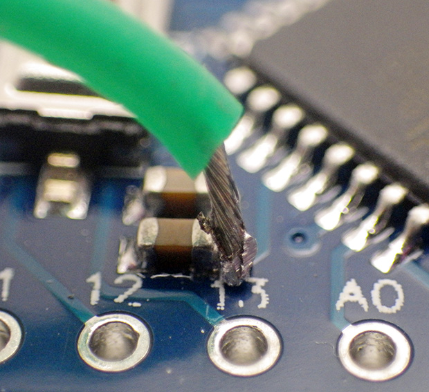
You can patch into the aref line on a Promini by soldering a jumper to the end of the little stabilizing capacitor.
Holy cow! A solution that only needed a few cheap parts and couple of pins. What the heck were those other guys gassing on about? My first thought was to try to take the output from Qwerty’s RC filter, and put it onto the Aref as they did in AVR 121. A compelling idea since putting the dither directly on aref means you don’t have to interfere with the sensor(s), and the same dither circuit would work for all of the analog inputs. In addition, I was using large resistance voltage dividers to monitor Vbat without wasting power and the high impedance forced me to add a capacitor to feed the ADC’s sample and hold input. I knew that low esr cap would kill any dither signal that was applied directly to the main battery divider.
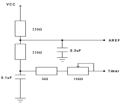
This L-P filter from AVR121 ap-note that everyone mentions works great, but modifying the circuit to give you other aref base voltages is a bit of a pain.
I tried many different combinations, but I never saw the voltage on aref that I expected. It took ages to discover that ~32k of internal resistance gets connected when you place an external voltage on the aref line, and that forms a ‘hidden’ voltage divider with your circuit. Grrr…
I did eventually get a few of those circuits working, but that internal resistor seemed to be slightly different on each board I tried, and I didn’t know if it was going to be stable with temperature, time, etc. Another important issue was that I was switching from the internal 1.1v aref to read the thermistor, back to using the default 3.3v for other readings during the logger operation. So to put the dither directly into aref meant I would also need some way to modify the baseline aref voltage on the fly.
Tweak the resistors & this circuit could give you variable arefs AND dithering.
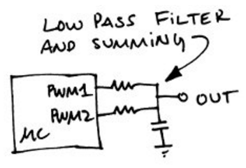
I suppose that a truly elegant solution would do that with a PWM/RC filter circuit generating a variable DC voltage, and using a second PWM input to add the much smaller dither signal. You could tune the dithers pk-pk amplitude to match the adjusted LSB, by the way you varied PWM2’s duty cycle (or by using the tone function) during the readings. But working that out would probably give me a host of other problems to resolve (esp. with timing) and I was after a simple solution, with the smallest number of parts. So I eventually abandoned the “dither on aref” approach.
This brought me back to Qwerty’s method of putting the triangular dither signal on the center of the thermistor bridge. My first task was to change that RC filter: lowering the 9mv swing on his 5v circuit to match the much lower 1.1mv/LSB you get when using the internal bandgap as aref.
The power supply ripple calculator at OKAWA Electric was a perfect tool for this job:


3.6mV was just an arbitrary ‘close enough’ point for me to start at as I had those components in the parts bin already. But if you see random flat spots in your oversampled readings at the default ADC speed, then try increasing the ΔV pk-pk of your dither signal a little bit.
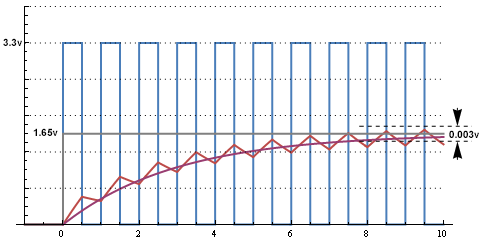
…which revealed that a 4.7MΩ/0.1uF RC combination would take the 3.3v 480Hz PWM on D6 and bring it down to ~3.6mv peak to peak. I immediately hopped over to the Falstad circuit simulator to see the see how this worked. To simulate an Arduino’s positive PWM, I used a 3.3v square wave source with an offset of 3.3v. The little 10nf coupling cap prevents the pins DC voltage from affecting the thermistor reading, and the 2k2 bridge resistor prevents the dither signal from being grounded out when the 10K NTC thermistor resistance gets very low. One of the coolest features of this simulator is that if you build a circuit with it, you can export a web link (like the ones above) that rebuilds the circuit instantly, so you can compare different versions simply by keeping those links in your log.
The RC settling time is shown on the Okawa calculator’s step response graph, or you can watch the voltage rise on the scopes in Falstad by restarting the simulation with the buttons on upper right.
I love using Falstad for “What happens if I do this?” experiments. Of course these usually fail, but in doing so they show me that there are things about a circuit that I still don’t understand. One thing that gave me a lot of grief when I started working with these dithering circuits was that I did not appreciate how much time they need to stabilize. This gets worse if you start disconnecting the thermistor divider to save power between readings.
So although I was getting smoother curves, and resolution that looked about 10x better than my raw ADC readings:

Here I’ve converted these 1024 sample curves to °C , and artificially offset each curve by 0.05° from the next to it for easier visual comparison. The one-shot 10bit ADC reading at the default 125kHz (ps 64) is in purple, with other ADC speeds: 250 kHz (ps32) in orange, 500 kHz (ps16) in green, and 1 MHz (ps8) in blue.

At the height of my coupling capacitor infatuation I produced this beast, thinking that if I could simultaneously add dither to a reference bridge I would be able to correct away ADC offset & gain errors, along with the offset caused by the dither signal, at the oversampled bit depth. But all those capacitors added artifacts to the readings when I reconnected GND through that mosfet, producing weird spikes in the data if I took readings less than two minutes apart (?)
…in any set of successive readings, the offset between the oversampled readings and the one shot ADC reading was changing depending on how long the PWM had been running. No problem I thought, I’ll just throw in another coupling cap to block that slowly rising DC voltage, and connect the ADC input on the thermistor side. Unfortunately replacing the 2k2 bridging resistor with a coupling capacitor forms a high pass filter with the thermistor itself, forcing you to increase the size of the cap to raise the filters cutoff frequency above your 480Hz PWM. But that increases your RC time constant so then the filter starts to act like a differentiator: distorting your nice triangular dither signal (see pg12 of this pdf), and in some cases even reverting it back to the original square wave you started with… Argh!
So the result of all that trial & error is the basic PWM->triangular dither method works well, but you have to wait for the RC filter’s output to stabilize or it messes with your accuracy. And you still end up with a small offset in the ADC readings of 1/2 your dither signals peak to peak, because the original PWM square wave can only be positive.
Crank it up
But no one wants to see a data logger burning away precious milliamp-seconds just twiddling its PWMs! With guidance from Nick Gammon’s fantastic ADC page, I had already been messing around with pre-scalars to increase the temporal resolution of my UNO DAQ. I was further encouraged by this line from AVR120 “For optimum performance, the ADC clock should not exceed 200 kHz. However, frequencies up to 1 MHz do not reduce the ADC resolution significantly.” …and there were some tantalizing hints that cranking up the speed might also increase the internal noise enough to make oversampling work better.
To figure out how fast your ADC is running:
System clock / prescalar = ADC clock, ADC clock /13 = # of ADC reads/second
The core clock speed on 3.3v promini style boards is 8 MHz, providing:
8 MHz / 32 = 250 kHz /13 = 19230 /sec (256 reads = 13ms, 1024=53ms, 4096=200ms)
8 MHz / 16 = 500 kHz /13 = 38000 /sec (256 reads = 6.7ms, 1024=27ms, 4096=108ms)
8 MHz / 8 = 1 MHz /13 = 76900 /sec (256 reads = 3.3ms, 1024=13ms, 4096=53ms)
Your sensors output must be stable while you gather these samples and this limits what kind of phenomenon you can measure. At the default ADC clock speed, trying to add six extra bits of resolution (46 = 4096 readings) means you can only capture about 2 samples per second. That’s pretty darned slow for data acquisition! In fact, it’s so pokey that some people implement ring-buffer schemes to provide access to an oversampled reading at any time, without having to grab a whole new set of samples. A neat trick if you are continuously monitoring a sensor that changes slowly, and you have enough memory to play with. Given the powers of 4 relationship between the different bit depths, it’s easy to see how you might hop-scotch through shorter 64 sample readings, and then combine those into a sort of rolling average version of a 256 sample reading if you don’t have quite enough ram for the full ring buffer approach.

My tests agree with the results posted at Open Labs. You can only push the ADC clock so far before you lose hardware bits, and this defeats the resolution gained from oversampling by making your accuracy worse. You can see this effect in the 1MHz line in the previous 1024 sample graph. Most AVR’s are lucky to get 9 ENOB’s at their default settings.
200 kHz is the ‘official’ ADC speed limit for 10 bit accuracy, but I didn’t see any significant difference between oversampled readings taken at the default 125kHz clock (ps 64), and those taken at 250kHz (ps 32). At 500kHz (ps 16) the readings were good most of the time, but during rapid temperature transitions the readings started to ‘wiggle’ as though the dither signal was occasionally dropping out. At 1MHz (ps 8) the curves wander around quite a bit, and I was seeing errors of ±0.05°C or more with some prolonged flat spots starting to appear. What’s interesting about this is that the triangular dither RC filter puts a capacitor across the thermistor, which should reduce the input impedance seen by the ADC and allow for faster readings. But this did not reduce the 500kHz wiggle / 1MHz wandering in any of my test runs. The ATmega328P datasheet quotes 2 LSB’s (typical) of absolute accuracy with an ADC clock at 200 kHz, but 4.5 LSB’s (typical) at an ADC clock of 1 MHz. There is no point in pushing clock speeds if the accuracy gets worse by that much in the process.
So you can always double the ADC clock speed for oversampling, but going up to 500kHz depends on whether you can live with the accuracy errors that prescalar creates. Those 500kHz wiggles become less evident as you progress from 256, to 1024, to 4096 readings, but that’s probably just an artifact of the smoothing. The other thing to keep in mind is that one full cycle of the 480Hz PWM takes ~2 milliseconds, but 256 readings at a 500kHz ADC clock takes only 6.73 milliseconds – so there is a high probability that dither signal synchrony issues creep in at the higher ADC speeds to produce offsets that affect the entire curve. Ideally you’d want the time you spend gathering the over-samples to be an exact multiple of the dither cycle time…
Let’s make some noise!
Hotter prescalars cut the oversampling time down dramatically, but I could not see how to avoid that RC settling time, which seemed to require about 50-60ms of PWM operation before the offsets became tolerable. So I went back to the proverbial drawing board and asked myself, what if forget about the triangle dither signal, and try oversampling with some sort of random noise?
The first hurdle there was: How was I going to generate this noise if the processor was already busy taking ADC readings? The beauty of PWM based dither is that it just chugs away in the background, leaving the processor free. As usual, Nick Gammon provided an elegant solution to this problem with code on his page about interrupts which showed how to read the ADC asynchronously:
unsigned long asyncOversample(int readPin, int extraBits)
{
int i=0;int j=0;
int var=256; //default is 4bits worth of oversampling
if(extraBits == 5){var=1024;}
if(extraBits == 6){var=4096;} //I’ve only included three options here, but hopefully you see the pattern
unsigned long accumulatedReading = 0;
adc_read=analogRead(readPin); // a throw away reading to connect the ADC channel
pinMode(5, OUTPUT); digitalWrite(5, LOW); // set the pin you are toggling to OUTPUT!
{adcStarted = false; accumulatedReading += adcReading; adcDone = false;i++;}
{adcStarted = true; ADCSRA |= bit (ADSC) | bit (ADIE);}
PORTD ^= B00100000; // XOR toggle D5 w green LED & 30k limit resistor (see below for details)
} // end of while (i < var)
if(extraBits == 4){accumulatedReading=(accumulatedReading >> 4);} // Decimation step for 4 extra bits
if(extraBits == 5){accumulatedReading=(accumulatedReading >> 5);} // 5 bits
if(extraBits == 6){accumulatedReading=(accumulatedReading >> 6);} // 6 bits
return accumulatedReading;
ISR (ADC_vect) // ADC complete ISR needed for asyncOversample function
{ adcReading = ADCL | (ADCH << 8);adcDone = true; }
(NOTE: copy/pasting code from WordPress blogs is almost guaranteed to give you stray/302 errors because of hidden shift-space characters that the layout editor inserts. If that happens to you, look at the line your compiler identifies, delete all the spaces and/or retype it slowly using only ASCII characters.)
Next I had to generate the noise itself. People use Zenner diode breakdown to produce random numbers, and connecting an analogue input to the collector of a run-of-the-mill transistor, with the emitter grounded and base open also creates noisier randomSeed(); input. But thought I would see if I could generate noise inside the processor, since there seemed to be no end of people complaining about the Arduino’s ADC in the forums. However when I actually tried to do this by connecting pull-ups, changing I/O settings, an every other kind of processor toggle I could think of, I got nothing. That ADC was solid as a rock until I started flipping the pins connected to the external indicator LED. Even then, the early results were wildly inconsistent, with the same code producing good oversampling on one unit, but not another.
Like the hidden resistor problem, it took me a while to notice that the random bunch of LEDs on my breadboard test units had significantly different forward voltage drops from one LED the next, and from one RGB color channel to the next. Once I realized how much that was affecting the results, it didn’t take long to determine that that the noise generating sweet spot (with 1.1v aref…) was somewhere around 0.04mA of pin current:

One-shot ADC reading shown in purple, with oversampled readings taken at 125kHz (ps64 default) in grey, 250kHz (ps32) in orange, 500kHz (ps16) in green. All readings are converted to °C, and I’ve offset these curves for clarity, as they would otherwise be on top of one another. You can clearly see the PS16 wiggle as the temperature falls, and the sharp eyed will notice there are still offsets between the different runs which were all taken in quick succession. These seem to be more apparent in the longer slower oversampling runs than they are in the the shorter faster ones… darn it…
Unlike triangular dither techniques, which will tolerate a fairly large ΔV, this noise based method stopped working (ie: flat spots started appearing) when the toggled pin current went below 0.02mA, and the curves became pretty scratchy above 0.06mA indicating there was too much noise. That’s a fairly tight range, and it was sheer luck that the 30k limit resistor I was using on my indicator LED’s brought me close enough to spot the effect. So my current target is ~0.04mA of pin current for 1.1v dithering. And there was nothing special about the LED being there either, as tests using a simple 82.5KΩ resistor from the PORTy ^= _BV( PDx/PBx ); toggled pin to ground produced good results. This is pure conjecture on my part, but if you assume the mosfets on the I/O pins have about 40Ω of internal resistance with 3.3v control, then 0.04mA pin current would produce a voltage drop of ~1.6 mv – which is suspiciously close to the 1.1mv/LSB resolution of the ADC with the internal bandgap set as aref. That puts this dither noise right in the 1-2x volts/bit recommendation from the literature.

Here I’m oversampling with 1024 readings from a 2x10MΩ divider which cuts the voltage of the RTC’s backup coin cell in half. 250kHz (psS32) in orange, and 125kHz(ps64) in grey. These are the raw readings with aref set to the default 3.3v and there is no capacitor on the divider. This is far beyond the 10k input impedance the ADC was designed for, but I think the many repeated readings you do with oversampling helps the 14pF sample&hold caps do their job. At this resolution, the CR2032 seems to be acting like another temperature sensor …(?) UPDATE: So this actually was the battery responding to temperature rather than the dithering method, which does not work with the rail voltage on aref unless you add a cap to the voltage divider.
This pin-toggling noise technique is not exactly a one size fits all solution, and the exact current required to induce ADC bit toggling will vary depending on which board you are using, and especially on which capacitors are being used smooth the output from the voltage regulator. So you will have to noodle around a bit to find the correct resistor value to use for your particular Arduino.
I’d start with a resistor value that draws enough current to give you a voltage drop on the digital pins mosfet that is close to 2x your ADC’s mV/LSB resolution. With 3.3v as aref (so 3.22mV/bit), I would use a pin resistor of about 27.5k for a pin current of 0.12mA which should cause a pin vdrop of ~4.8mV. Given that limit resistor for the pin13 LED is usually around 1K, you might be able to toggle that on-board LED to generate this dithering noise without adding any extra components.
With 5v control logic, the mosfets controlling the digital pins are more fully turned, so the pin resistance is somewhat lower; around 25-30 ohms. With 5v on aref your resolution is about 4.88mv/bit, and the dither resistor would have to pull around 0.39 mA to shake the rail with a vdrop twice that mv/bit, so the dithering resistor would need to be somewhere around 12.8 kΩ.
On new builds I will measure the forward voltage drop of the indicator LEDs and change the limit resistor to give me the current through those I need to generate dither noise. That way I don’t need to any new digital lines for the oversampling process, though this will entail checking every LED, as there is significant vf variation between batches. The blue channel on the RGB’s I have lying around have a vf of ~2.473v, so 0.827v will be left for the resistor to cover with a 3.3v rail. To achieve a target pin current of 0.12mA the limit resistor (for that blue LED) would have to be 0.827v/0.00012mA = 6.89kΩ.
This method is also critically dependent on the tiny capacitor stabilizing the aref voltage. When I tried it on the units I had left over from the ‘dither on aref’ experiments, the pin toggling method did not work if the aref stabilizing capacitor had been removed. I also suspect that the voltage on the capacitor ‘adjusts’ to the noise pulses over time, which might be causing the 0.02C difference between the 256 & 1024 readings shown above. So there could be another settling time issue if you take a large number of over-sampled readings in rapid succession. Larger caps stabilizing the rail voltage on breakout boards may also affect the method. And then there’s the fact that within a processor it is practically impossible to ensure, ALL timers, interrupts, and other processor activities operate randomly with respect to the timing of the ADC conversions. So you can be sure we are generating ‘noise’ that is not random, so there will be offsets created that you will need correct for.
This technique will work with any resistive sensor being read with a simple voltage divider, provided there are no capacitors nearby to smooth out the noise which is vital for oversampling. I’m not going to pretend to understand all the math behind it, but it’s probably safe to say you can add somewhere between 2-5 extra bits of resolution to your ADC before the technique suffers from limiting problems somewhere else. Although the 256 sample curves are a bit gritty, you can make that many samples with the ADC clock at 250kHz in ~13milliseconds, which doesn’t impact the power budget much. If something interesting starts happening with your sensor, you can enable another bit or two of resolution on the fly to zero in on the phenomenon.
Overall, the results from oversampling with toggled-pin noise are not as smooth as the curves you get with a well tuned triangular dither, but I’m happy to trade that last bit of synthetic resolution for a method that’s instantly available on all of the ADC inputs. The icing on the cake is that I won’t have to add any extra circuitry to use oversampling on the fleet of loggers already on deployment, because all I have to do is toggle the indicator LEDs they already have on board, since their limit resistors were already in the current range I need…YES!
Addendum 2017-04-26:
I’ve moved on to calibration, and in the process I learned that regulator & bandgap voltages change a fair bit with temperature. So it’s probably not a good idea to use the internal bandgap on aref with this oversampling method if you want thermistors calibrated over a wide temperature range. But I did it anyway.
In those tests I used a 688k series resistor with a 100k thermistor, so I was far from divider’s optimum of Rseries=RTnominal. I was taking 1024 oversamples, adding five oversampled bits to ADC, and I was using the internal bandgap voltage on aref, which added another bit. Since I was on the tail end of the divider sensitivity curve, the effective resolution changed quite a bit over the range: the output shifted from ~0.0018°C/bit at 20°C, to about 0.0038 °C/bit up at 40°C. This is better resolution than some people achieve reading thermistor bridges with the 16bit ADS1115, though gathering all those readings means I can only capture 18 samples per second – even with the ADC clock at 250kHz.
I have a long way to go before I reach the accuracy levels you see at the geotechnical high end, but I think that’s still good for readings with a humble Arduino ADC!
Addendum 2017-09-24:
Several people have contacted me about their attempts to get this ‘pin-toggling noise’ method working with different Arduinos at higher voltages. If I had to summarize the kernel of understanding that was missed in the unsuccessful cases it is this:
If you jiggle one part of the system with noise – stabilize the other part.
It does not matter if the noise shows up on aref, or on the sensors output, so long as it is not present in the same form on both. With the bandgap 1.1v as aref, you can rely on that to be the stable side, so you want the voltage divider with your sensor not to have a capacitor on it, since the sensor side needs to shake by ±2 LSB volts when the pin is toggling. The internal reference is slightly different on each individual chip (from 1V to 1.2V), so you’ll also need to “calibrate” if you go this route. Don’t forget to throw away the first reading after changing the analog channel, and if you have a high resistance voltage divider, add a one ms delay after that first analog read.
If you use the rail voltage as aref (the default) with an un-stabilized voltage divider then your pin toggling current shakes the aref ground in perfect synchrony with the ground line on your sensor, and no matter how many samples you read & decimate you will never get beyond the 10 bit resolution of the ADC. So to use the rail as aref when oversampling you need a small (around 0.1uF) capacitor across the lower half of your thermistor divider so the sensors input to the ADC becomes the stable side. It’s also a good idea to remove the little 0.1uF stabilizing capacitor that’s normally present on the aref line, since it’s whole purpose is to prevent aref from jittering.
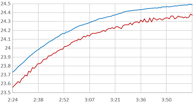
Degree Celsius vs. Time with lines offset from each other for easier visual comparison: The blue line is over-sampled output from a pro-mini clone reading a 100KΩ NTC Therm/100KΩ series voltage divider. Aref was set to the 3.3v rail, with a 100nF capacitor parallel to the thermistor on the low side. A 0.12 mA pin-current provided sufficient noise for dithering 1024 readings, delivering an effective resolution of ~0.0028° at 24C. For comparison, the red line is the output from an I2C si7051 sensor on the same logger, with a resolution of 0.01C.
The question of which side should be treated as stable comes into play when you want to over-sample analog output from more complex sensor circuits. If the circuits on a sensors supporting breakout board are already doing a good job of stabilizing output, say with feedback, caps and some sort of buffer at the end of an amplification cascade, then you have no choice but to set aref to the rail voltage and shake that. I’ve had success with this approach and a complex sensor circuit on a 5v Nano, by pulsing a pin connected to ground through a 12KΩ resistor (~ 0.4 mA of pin current).
No matter which side you shake, everything else in your system is feeling this noise to some extent, and this may cause issues with sensitive sensor IC’s, or with micro-controllers other than the 328p. Of course, the higher the aref you use, the more of a voltage swing you need to introduce for sufficient dither. The effect of the pin current is also being limited by capacitance distributed throughout the system, which varies from board to board, so this is definitely a “try it an see” method: when it works it really works, producing smooth curves with no hint of the underlying 10-bit ADC peaking through. (Most of the time I get acceptable oversampling results toggling the green channel of a three color RGB indicator LED with ~24k limit resistor but that is somewhat dependent on the LED’s forward voltage. When in doubt, use a smaller limit resistor to increase the pin current – and check the actual value with a DMM)
If you see any flat spots or rounded stair steps in your temp. data, especially in areas where the changes are occurring slowly over time, then you know the dithering is not working:

This is an example of the natural noise problem: oversampled (blue line) thermistor readings achieved high bit depths the refrigerator (left), but developed flat spots in the room (right) where the changes were happening more slowly. This was a test run with the noise circuit disconnected,which I followed with run using the same code +noise applied so I could compare the two. Doing two runs (with & without dithering) is good general approach to use when testing a circuit that uses oversampling.
Any natural signal variation over your sampling interval will make it look like your generated dithering noise is sufficient for oversampling, when it is not. The photo above shows how that this test is almost impossible to do in the refrigerator, because the natural on/off cycle of the compressor generates enough change/time to make oversampling work without dithering.
 With stabilizing capacitors on the voltage divider you also have the trickier problem of spotting the influence of the RC time constant when you only power the voltage divider during readings. Oversampling before the cap is fully charged will provide more than enough change in the readings to hide inadequate dithering. In fact, if you scale the capacitor/series resistor combination, and sample over the 3T-5T interval after applying power, you get reasonably good oversampling results with no other noise in the system. In some ways, using RC rise time is better than pin toggling when you are using the rail as aref, since it does not have to fight against the other capacitance distributed around the system to produce a delta on the ADC readings. I’d use this rather than pin toggling with aref=rail if it weren’t for the fact that capacitors can have the worst variation coefficients of any electronic component you are ever likely to run into.
 Garden variety Y5V ceramics vary by up to 82% over their rated temperature range, and even the X7R’s that most engineers use vary by +/-15%. I might be able to calibrate that thermal variation away, but for environmental monitoring the drift over time is a much bigger problem: with caps commonly loosing 10-15% of their rating over the first year (~8900 hours) of operation. There are stable NPO rated ceramic caps out there, but they are only available in relatively small pF sizes, and a good 0.1uF NPO cap will set you back about $7 each even if you buy them in quantity, so that part alone costs more than a decent IC based temperature sensor.
Plastic film capacitors have much better thermal coefficients: Polyphenylene sulfide (PPS ±1.5%) or Polypropylene (CBB or PP ±2.5%). A quick browse around the Bay shows those are often available for less than $1 each, and the aging rate (% change/decade hour) for both of those dielectrics is listed as negligible. The trade off is that they are huge in comparison to ceramics, so you are not going to just sneak one in between the pins on your pro-mini.
For most rail-as-aref situations, Qwerty’s PWM based dither method (mentioned at the beginning of this post) is a more robust way to dither with cheap ceramic caps, since it can tolerate significant variation in a way that does not affect your accuracy that much – but you still have to keep an eye on the circuit settling time.
Addendum 2017-10-15:
Just came across AN2668 from STMicroelectronics which sums the input signal and triangular dither signal through an op-amp before sending it to the ADC:

Still seems like a lot of work to me, although that ap-note does have me wondering if the pin-toggle dither noise is actually Gaussian…?
Addendum 2019-03-25:
Pin Toggled Oversampling has been delivering solid results for more than a year now in the field, but I’ve recently been developed a new method for reading thermistors with the Input Capture Unit on pin D8. Micro-controllers count time much more precisely than ADC’s measure voltage, so this timer based approach delivers more resolution than 16-bit oversampling in about 1/10th the time & power. That doesn’t meant that we’ll stop using oversampling – just that there’s another technique for high resolution sensor readings with an Arduino. That ICU method also works if you want to use a Single Diode as Temperature Sensor, including your indicator LED!
Addendum 2020-05-21:
Even with oversampling to boost ADC resolution there’s still one analog sensor situation that forces me to go to an external ADC module: Differential readings on bridge sensors. In those cases I use an ADS1115 module, which can also generate interrupt alerts so I can sleep the main processor during the conversions.

This is a great article, thank you for taking the time to explain things in such great detail.
It took several months of test runs to get it all sorted, and whenever I run into one of those situations it pains me to think that there might be other people out there re-inventing the same wheel. And throughout the project I’ve been cribbing notes from people like Gammon, Whippler, Greiman, Tillart, and a host of others. So these long tutorial posts are a way to pay it forward…
Pingback: Arduino analogRead pitfalls | The bright side
Fantastic stuff. Read this over a cuppa, cherry-picked a few titbits, and got a really satisfying result with an Arduino nano, a cheap-as-chips slimline thermistor, and a handful of passives. Results better than much more expensive ‘proper’ temperature sensors lying around here! Dread to think how much work it would have been without your helpful guide, so thanks for sharing your journey for the rest of us to learn from!
One thing to keep in mind is that I do see tiny offsets between the different bit depth runs. So I’m pretty sure that the pin toggling is not generating perfectly Gaussian noise, in fact with all the chances for timing synchrony here, I’d be really surprise if it was. I take care of that in the calibration since I have to do that for every unit anyway, but I can see how triangular dither would make more sense in a production environment where you need inter-changeability. But if you can afford the time to calibrate at each bit depth you want to use, then this is a super easy method to increase resolution, and I’m really surprised it does not get more attention in the DIY/Maker crowd.
Had same idea about 1) averaging, and 2) dithering.
For 1) I’m going to implement a constant-current source (using a 2N3819, and a resistor wired gate-source) to charge a bunch of ceramic capacitors to give me a nice slow ramp, then output the numbers (floating point) of both the non-averaged, then the averaged data. Stuff those into excel or libre office’s ‘calc’.
My problem with averaging alone is that if the voltage is a rock-steady DC voltage, sitting about 3/4 between bits, averaging won’t do anything – it’ll be reported as being at the lower bit level, constantly. (For the same reason I can’t understand ‘escape velocity’ – the damn rocket’s going up anyway, just keep burning, it’ll get there some time…)
So, 2). It needs a bit of help. For that, I need a bit of noise. Well, just under a bit…Plan is to use a 2V7 zener, pipe its voltage via a pot. then a small (1nF?) capacitor to add a tad of uncertainty and nausea to the signal.
Being unemployed, I can’t rush out and buy an Arduino – gotta wait till my cheap copy comes from China….
I’d avoid ceramics for these approaches myself. Too much variation (esp ageing). I was not able to find a simple Zenner breakdown noise circuit that I could just add to any generic signal (ie: one without opamps) if you find one send me the link to include here.