

Testing configuration w differential reads from a piezo triggering burst-samples with a $1 ADS1115 module.
The 16-bit ADS1115 has a programmable amplifier at the front end, with the highest gain setting providing a range of +/- 0.256 v and a resolution of about 8 micro volts. But readers of this blog know you can already approach 14-16 bit sensitivity levels with Arduino’s ADC by oversampling with lower Arefs & scaled ranges. PA1EJO demonstrated a ADS1115 / thermistor combination which resolved 5 milli Kelvin, but we can reach that resolution on our NTC’s using the ICU peripheral with no ADC at all. The beauty of time-based methods is that they scale gracefully with sensors that change over a huge range of values. So why am I noodling around with this ADC module?
The primary attraction is this ADC has differential inputs. This is especially useful with Wheatstone bridge arrangements. A typical combination would be a two element varying bridge, and an inexpensive voltage reference like the LM4040, or the TL431. Adding the second sensor doubles the voltage swing, and the ADC’s -32768 to +32767 raw output fits perfectly into Arduino’s 16-bit integer variables. It’s also worth noting that unlike most ADC’s – the ‘volts per bit’ via the gain settings are independent of the rail voltage supplying the chip. This means that the ADS1115 can measure it’s own supply using that internal reference without a divider. The drawback of that is I have to set full-scale as +/-4.096V on my 3.3v loggers, so the ADC only uses ~80% of the bit-range.
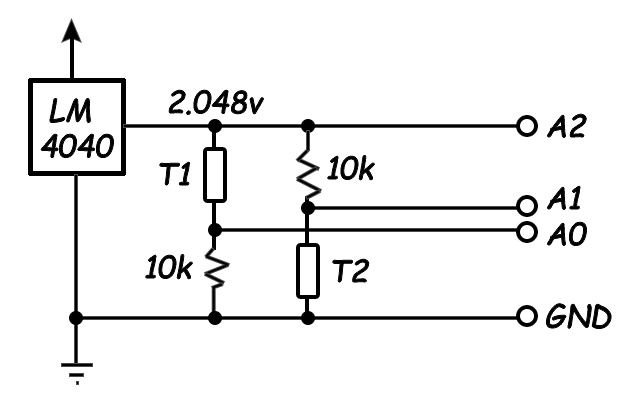
Read the difference between A0 and A1 as a differential input, and read A2 as a single-ended input. That will give you an ‘almost‘ ratio-metric measurement because you record every voltage affecting the output. (although since the supply is not Aref like it would be in a regular ADC – the uncorrelated noise in the LM4040 excitation voltage ‘between’ those two readings will not get corrected) I treat the ref. resistors as ‘perfect’ in my calculations, which forces their tempco errors into the thermistor constants during calibration.

The diodes shunt any voltages that exceed their vF, protecting the ADC from spikes beyond the +/-0.256v range at high gain. AND the leakage that Shottky’s are known for bleeds away residual charge on the piezo, preventing drift from the 1.65v bias point. All the data presented in this post used this circuit. Other diodes, or even garden variety LED’s, could also be used to clip the signal at different voltages. Most have far less leakage than Shottkys, so you might need to add a large value bleed resistor. If you do end up with an offset, an old trick is to run a very aggressive low pass filter on your readings to obtain the offset and then remove it by subtraction.
Piezos can also be read with bridge arrangements if they are physically connected with alternating polarities, but that’s not usually the case for active sensors. I have a new project in the works where the sensor will only generate +/- 5mv, and I’d like to see if capturing signals that small is even possible with the ADS1115. To reveal where the weak points are I’ll test it with a single piezo disk reading at the highest gain and fastest sample rates. At this sensitivity a 5mv swing will only produce ~640 counts. With my signal only covering 2% of the bit range, I’m hoping that the differential readings will compensate (?) for noise on the rails. The data sheet warns about low input impedance (710kΩ) but I don’t think that will affect this test. Another significant limitation of the ADS1115 is that, like the Arduino driving it, no voltages below GND, or above Vcc are allowed on any input. Bridge arrangements automatically bias to the mid-point, so while the tie-in points might go ‘negative’ relative to each other, they are still positive relative to GND on the ADC. For single sensor applications with +/- output, you need to provide that biasing with a couple of resistors.
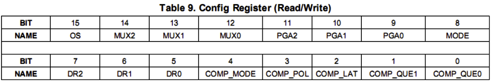
An often overlooked feature of the ADS is the programmable comparator which can set threshold alarms on the ALRT/RDY output. Most loggers operate with fixed interval sampling, but this makes it difficult to measure things like airborne exposure peaks for chemical vapors; even with short intervals. Sensor-triggered sampling can also save battery power by letting you sleep the CPU – especially when you are monitoring environments that are only ‘active’ during certain seasons, or with rainfall events. The different comparator modes on the ADS1115 also offer some interesting possibilities for system control.
Driving the ADS1115:
This chip’s been around for a long time, so there are several libraries to choose from. And, as usual, many of them don’t support the features that a project building loggers would be most interested in. I suspect this is because wireless coms use such a prodigious amount of power that few in the IOT crowd would bother writing efficient code for chips that already auto-sleep. The Adafruit library even inserts 8ms delay statements – wasting cpu power and throttling the sample rate to 125sps. Rowberg’s I2Cdevlib does a better job with setConversionReadyPinMode() functions. But his code example only polls the I/O status, rather than using the hardware interrupts available on the same pin.
Perhaps the easiest starting point for beginners is the ADS1115 lite library. This is a stripped down version of Adafruit’s lib. but Myers has removed the explicit delays and replaced them with a do-while loop which polls the Operational Status bit to see when the ADC has a new reading in the output registers. This minimalist approach uses only two main functions:
triggerConversion() – Sets config register bits & then writes that register back to the sensor (which automatically starts a single-shot reading) The ADS1115 auto-sleeps after the reading.
getConversion() – A do-while loop forces the CPU to continuously check the Operational Status bit. That bit change breaks the loop, and getConversion then reads the 16-bit output register.
With this single-shot approach, a short for-loop takes burst of readings:
#include <ADS1115_lite.h> // https://github.com/terryjmyers/ADS1115-Lite
#define numberOfSamples 500
int16_t ADS1115raw[numberOfSamples];
setMux(ADS1115_REG_CONFIG_MUX_DIFF_0_1); // uses #define statements
setSampleRate(ADS1115_REG_CONFIG_DR_860SPS); // for the config bitmasks from
setGain(ADS1115_REG_CONFIG_PGA_0_256V); // the original Adafruit library
for (int i = 0; i < numberOfSamples ; i++) { // I usually read 500 samples
triggerConversion(); // during testing, which fills the
ADS1115raw[i] = getConversion(); // the serial plotter window nicely
}
In single shot mode, you have to re-write the configuration register every time you want a reading:
Myers triggerConversion() function sets the config register with a common Bitwise-OR method. I’m going use this as a starting point, tweaking a few things for better readability and including my standard a 16-bit register functions so this page doesn’t scroll on forever.
(also note that in addition to my typos, wordpress inserts a ton of invisible cruft characters that will mess with the IDE – so don’t copy/paste directly from this post…)
uint16_t config = 0; // All bits set to 0
config |= _rate; config |= _gain; config |= _mux; // sets matching bits to 1
bitSet(config, 8); // MODE set to 1 = single-shot & power-down (the default)
bitSet(config, 15); // setting oneshot bit starts a conversion, bit goes low when done
i2c_write16bitRegister(ADS1115address, ADS1115_REG_POINTER_CONFIG, config);
Sensor Triggered Sampling:
Let’s use the comparator to start each burst of readings in response to me tapping the surface of the desk that the piezo sensor is resting on. Although Myers polling method doesn’t use the ADC’s ALERT/RDY output, we are already set up for triggered bursts because all the comparator control bits were zeroed with config = 0 at the start.
COMP_MODE: 0 => Traditional hysteresis mode (On above Hi_thresh, Off below Lo_thresh)
COMP_POL: 0 => ALERT active brings the pin LOW
COMP_LAT: 0 => NON latching
COMP_QUE: 00 => ALERT after one reading above Hi_thresh (01=2reads, 10=4reads)
With this as the starting point all you have to do to initiate comparator threshold alerts is load some non-default trigger values into the Hi_thresh & Lo_thresh registers. Hi_thresh must be greater than Lo_thresh, and you have to use ‘2s complement’ values
// set Lo_threshold register (0x02) to ‘2’s complement’ equivalent of decimal 250:
i2c_write16bitRegister(ADS1115address, 0x02, 0x00FA);
// set Hi_threshold register (0x03) to equivalent of decimal 300:
i2c_write16bitRegister(ADS1115address, 0x03, 0x012C);
Now we need a way to make the processor respond the ADC’s alert. If I wanted to use the same power wasting methods you find in most sensor libraries, I’d connect ALRT/RDY from the ADC to any digital input pin, and poll the pin until it goes low:
void pollAlertReadyPin() { // this code will time out eventually
for (uint32_t i = 0; i<100000; i++) {
if (!digitalRead(AlertReadyPin)) return; }
Serial.println(“Timeout waiting for AlertReadyPin, it’s stuck high!”);
}
This might be OK for an IOT sensor hanging off of a wall-wart. But for logging applications a hardware interrupt based approach lets you save power by sleeping the processor until the trigger event happens:
void INT1pin_triggered() {
INT1_Flag = true;
}
// – – – – – – later on – – – – – – – – in the main loop – – – – – – – – – – –
uint16_t config = 0; // All bits set to 0
config |= ADS1115_REG_CONFIG_MUX_DIFF_0_1 ; // using #defines from Adafruit lib
config |= ADS1115_REG_CONFIG_DR_475SPS ;
config |= ADS1115_REG_CONFIG_PGA_0_256V ;
bitClear(config, 8); // MODE set to zero = continuous sampling – redundant here
i2c_write16bitRegister(ADS1115address, ADS1115_REG_POINTER_CONFIG, config);
i2c_write16bitRegister(ADS1115address, 0x02, 0x00FA); // set Lo_thresh = 250
i2c_write16bitRegister(ADS1115address, 0x03, 0x012C); // set Hi_thresh = 300
// ALRT/RDY output from ADC is connected to the hardware INT1 pin
set_sleep_mode(SLEEP_MODE_PWR_DOWN);
bitSet(EIFR,INTF1); // clear pre-existing system flags on INT1 pin
noInterrupts ();
attachInterrupt(1,INT1pin_triggered,FALLING);
INT1_Flag = false; // reset the flag before the do loop
sleep_enable();
do { // loop keeps the processor asleep until INT1pin_Flag = true
interrupts ();
sleep_cpu ();
noInterrupts ();
} while ( !INT1_Flag );
detachInterrupt(1);
sleep_disable ();
interrupts ();
// after waking, reset the threshold registers to their defaults to disable the ALERTs
i2c_write16bitRegister(ADS1115address,0x02,0x8000);// Lo_thresh default = 8000h
i2c_write16bitRegister(ADS1115address,0x03,0x7FFF);// Hi_thresh default = 7FFFh
// now gather single-shot readings as before
for (int i = 0; i < numberOfSamples ; i++) {
triggerConversion(); // resets the config register to single shot mode every cycle
ADS1115raw[i] = getConversion();
}
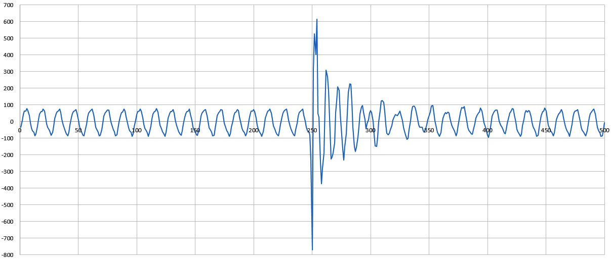
With 200 / 300 set as thresholds, tapping the desk beside the piezo produced:
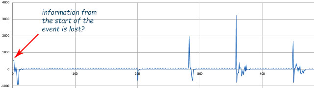
RAW ADC output vs Sample Number: Threshold triggered: A0-A1 differential, 475SPS, 16x PGA,500 samples
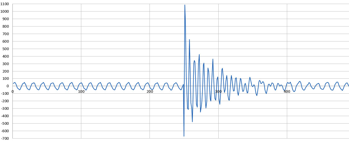
With readings above 2000, I was hitting the desk a bit too hard for that 5mv target range. And 475 samples-per-second is not quite fast enough to show piezo sensor behavior. Zooming in also shows that the ADC was aliasing through some background signal:
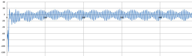
RAW ADC output vs Sample Number: ADS1115 & piezo sensor, A0-A1 differential, 475SPS, 16x PGA, 500 samples
That’s a classic ‘mains hum’ problem. Annoying, but from a research perspective the loss of information from the start of the event was is a more of an issue: What happens if we only get one chance to record our event?
Pretriggered acquisition:
To capture infrequent events, I need to start acquiring data before the reference trigger. And since the waiting period is unknown, those readings need to go into a circular buffer that wraps around and stores each new sample over the oldest one in memory. With this approach the trigger event actually serves to stop the acquisition rather than to start it. And you want to do this gradually, so the samples in the array represent a “slice-in-time” covering the entire event.
The real trick is to sleep the main processor as much as possible during the pre-fetch period. In continuous conversion mode the ADS1115 can alert completion with an 8 msec pulse, but with only one alarm output, the ‘threshold detection’ will have to be done in software:
void INT1pin_triggered() {
INT1_Flag = true;
}
// – – – – – – – – in the main loop – – – – – – – – – – –
uint16_t config = 0; // All bits set to 0
config |= ADS1115_REG_CONFIG_MUX_DIFF_0_1 ; // #defines from Adafruit lib
config |= ADS1115_REG_CONFIG_DR_860SPS ; // the max speed
config |= ADS1115_REG_CONFIG_PGA_0_256V ; // maximum gain
bitClear(config, 8); // MODE set to zero = continuous sampling – redundant
i2c_write16bitRegister(ADS1115address, ADS1115_REG_POINTER_CONFIG, config);
// continuous mode 8ms ‘pulses’ require these specific values in the threshold registers:
i2c_write16bitRegister(ADS1115address, 0x02, 0x0000); //Lo_thresh MS bit must be 0
i2c_write16bitRegister(ADS1115address, 0x03, 0x8000); //Hi_thresh MS bit must be 1
// ALRT/RDY output from ADC is connected to the hardware INT1 pin
// housekeeping variables for sampling loop control:
bool triggerHasHappened = false;
int countdown = numberOfSamples/2; // sets # of samples taken AFTER trigger event
int countup = 0; // If triggered before the array is 1/2 full, countup used to fill remaining
int arrayPointer =0; // tracks where we are in the circular buffer
set_sleep_mode(SLEEP_MODE_PWR_DOWN);
// now loop forever till trigger event starts the countdown
// then collect numberOfSamples/2 more readings
while ( countdown>0 ){
bitSet(EIFR,INTF1); // clear any pre-existing system flags on INT1 pin
noInterrupts ();
attachInterrupt(1,INT1pin_triggered,FALLING);
INT1_Flag = false; // reset the flag before the do loop
sleep_enable();
do // short sleeps while waiting for each ADC reading
{ interrupts (); sleep_cpu (); noInterrupts (); }
while ( !INT1_Flag );
detachInterrupt(1); sleep_disable (); interrupts ();
// load one reading into the ADS1115raw array
ADS1115raw[arrayPointer] =
i2c_read16bitRegister (ADS1115address , ADS1115_REG_POINTER_CONVERT);
// here I’m using 200 as the threshold reading to start the countdown
if (( ADS1115raw [ arrayPointer ] > 200) && ( !triggerHasHappened ) ){
triggerHasHappened = true; //only needs to occur once
if (countup < (numberOfSamples/2)){ // trigger happened b4 array was 1/2 full
countdown=countdown+((numberOfSamples/2)-countup);
// increases countdown by the difference so you always capture numberOfSamples
}
}
if ( triggerHasHappened ){ //then only fill the last half of the array
countdown = countdown-1; // limits the number of new readings
}
// advance arrayPointer with ring-buffer MODULUS formula:
// automatically goes back to zero when the pointer reaches the end of the array
arrayPointer = (arrayPointer + 1) % numberOfSamples;
countup=countup+1;
} // =====end of while ( countdown>0 ) loop======
sleep_disable ();
// reset the registers to startup defaults to stop ADC continuous running
i2c_write16bitRegister(ADS1115address,ADS1115_REG_POINTER_CONFIG,0x8583);
//sets: ±2.048V,128SPS,NoCOMParator,AIN0&AIN1,Trad,NoLAT,NoALERTs,ActiveLOW
i2c_write16bitRegister(ADS1115address,0x02,0x8000); // Lo_thresh default
i2c_write16bitRegister(ADS1115address,0x03,0x7FFF); // Hi_thresh default
//read the ADC output registers to remove any residual ALERT/RDY latches
i2c_read16bitRegister(ADS1115address,ADS1115_REG_POINTER_CONVERT);
Setting countdown = numberOfSamples/2 centers the event in the array. (although 1/3 to 2/3 split might be better?) A tap on the desk with a pencil produced a +/- 5mv swing (~640 raw counts), and my breadboard proto circuit is picking up almost 100 counts of mains hum.
RAW ADC output vs Sample #: 860sps, 16xPGA, diff. A0-A1, USB powered from laptop
Losing 20% of my available signal range to background cruft is a problem. Adding a $10 USB isolator, reduced that by about 1/3. But the 60 Hz signal was still distorting the shape of the waveform significantly or we’d be seeing a smoother damped harmonic..
RAW ADC output vs Sample #: 860sps, 16xPGA, diff. A0-A1, with USB isolator. Hit the desk a bit to hard on this one.
My first thought was ‘This is a well behaved, repeating signal – I’ll just subtract it out’. Unfortunately 860 SPS is not a multiple of 60Hz, so simple corrections tend to pass in & out of phase with the hum – eventually making the situation worse. The misalignment means we’d need to do some serious math for the correction at 860SPS, so I’m probably not going to be implementing that filtering on an 8-bit processor. Alternatively I could go back to single shot sampling and use the processors internal timers to only request each new sample at some whole number multiple of the 60 Hz mains cycles, like for example at 600 readings a second. The maximum possible would be 840, and you’d might want to add some jitter to that.
Next I tried a run from batteries only, with the nearby electrical devices all turned off. This reduced the mains hum by ~10x relative to the USB tethered operation:
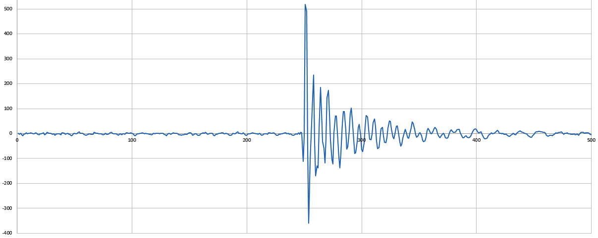
RAW ADC output vs Sample #: 860sps, 16xpga, differential A0-A1, Battery powered logger
A dramatic improvement, with the ‘pre-event’ noise falling below +/- 10 counts. Most of our field deployments are in caves and this ADC looks like it has an acceptable noise floor for work in that kind of isolated environment . But the project also has a teaching component so I’d also like to use this ADC module in classroom settings. Zooming in on that last graphs shows that working with tiny sensor signals will be challenging if we are anywhere inside a building – even if the resting state of the system looks OK:
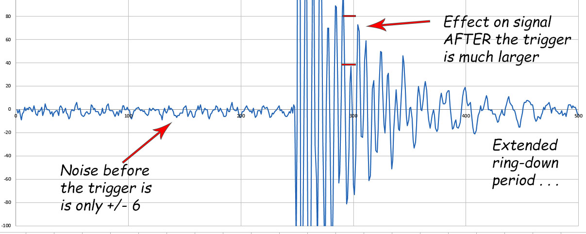
Once the sensor is set in motion, even tiny interferences from the mains will reinforce each other before the system settles again. Even if I use internal timing control to synchronize the readings with a whole number multiple of the mains, it looks like I still won’t be able to use the ‘before’ data to fully correct the ‘after’ effects. This might be specific to way piezo sensor’s resonate, but I’ve got some homework to characterize the effect before we start building a student lab with this module.
Looking in the bright side, even with a power hungry 1284p based logger, the current draw while capturing the pre-event readings averaged less than ~450 μA for the whole system.
The path forward:
The successor to the ADS1115 is the 24-bit ADS1219 which reads up to 1000 SPS (20 Effective Bits, PGA x4). It has integrated input buffers to allow measurement of high impedance inputs & separate inputs for analog vref (true ratiometric!) and digital power/ground. This gives you more options to mitigate power supply noise, which as we’ve seen can be important for small signals. It also offers some built in 50-Hz and 60-Hz rejection, but only at slow sample rates. The ADS1115 is a delta-sigma converter so it continuously samples its inputs (oversampling @250kHz internally) which causes a transfer of charge. From the outside, this appears as a resistance which depends on the sampling rate and depends on the gain of the input stage. Higher gain for more sensitivity yields lower effective input resistance which adds in parallel to the resistance of your sensor circuit. So if you were reading the output of a voltage divider (equivalent) the ADS1115 itself would change the result. So input buffers on the ADS1219 are a welcome addition.
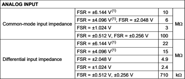
The low input impedance of the ADS1115 can prevent you from using the higher gain settings in differential mode unless you add an opamp/buffer to prevent the ADC from putting to much drain on the sensors output. This is really what separates the ADS from ‘Instrumentation quality ‘ components which generally have much higher input impedances.
There are other 24-bit options in the hobbyist market like the HX711 (24-bit, PGA x32,64,128 – but only x32 on the 2nd channel? ) that is commonly sold with load cells, and I’ve seen it mentioned that the SPI HX711 works with libraries written for the ADS123x series. The ADS1232 (24 bit, fixed x128 gain) might be a easier option for dedicated bridge sensors, and they can be found on eBay for ~$7. One advantage of the ADS123x over the HX711 is that they have a switch that can shut off current to the sensor bridge when the ADC is in Standby or PowerDown mode. Of course then you have the problem that load cells take some time to warm up when power is applied, often taking several minutes to stabilize. You occasionally see seismometer projects using the 32-bit ADS1262, which has a sensitivity >1000x better than the 1115, but with a fairly slow sample rate.
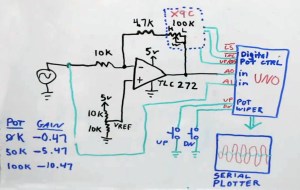
This circuit from Gadget Reboot shows one method of obtaining programmable gain control using an X9C digital potentiometer in the opamp feedback loop. See: Part1 & Part2 The DS3502 gives you an I2C bus version with the same 10k range, though I have no idea what the long term stability of these digital pots is. And 5% tolerance is a bit grim.
But this little experiment has me wondering if for signals in the 1mV range it might be better to spend more effort amplifying rather than moving to higher resolution ADCs. If the real issues are going to be noise and drift, then those might be easier to deal with if the level is boosted first. Microphone preamps can be made from a single 2N3904 transistor and placed in front of a (200x) LM386 modules for less than 50¢ though I suspect there might be lots of distortion. A general purpose (100x) LM358 might do the job on its own, or a (1000x) INA333 or AD623 modules (with the trimpot) which can usually be had for less than $6, as can the AD8221AR. The INA129-HT gets you to 10,000x for ~$9. What I’d really like is an amplifier with the same simplicity of the ADS1115’s PGA. If anyone knows of a cheap I2C/register controlled opamp module in the hobby market price range, I’d love to hear about it.
Addendum 2020-05-24: Interrupt latency with wake from sleep
I just watched an interesting video about the sleeping the ESP32 processors and was quite surprised to find out how long (150 µS) and how variable the hardware interrupt latency is on these expressive processors. This set me down the rabbit hole to find out what the latency is on the AVR processors. On a normally running processor you enter the ISR in 23 clock cycles, which is about 1.5µS @16MHz. However if you loop through POWER_DOWN there are extra things to consider like the fact that disabling the BOD in software (just before sleep) is going to add 60 µS to your wake-up time. You also have an ‘oscillator stabilization period’ of 16k CPU cycles with a standard external oscillator. [see Sect.10.2 of the datasheet] The net result is that the Wake/Start-up time for a 8MHz Arduino is ~1.95ms. AVR’s with 16MHz clocks like the one I used for this test should have a wake-up time of less than 1ms. So I was actually cutting it close to combine full POWER_DOWN sleep & the ADS1115’s highest sampling rate. A 3.3v Pro Mini based build @8MHz would not have kept up unless I used SLEEP_MODE_IDLE to keep the main oscillator running which avoids that long stabilization delay.
Other projects using this ADC:
While I’m giving it a B rating for my current use case, this $1 ADC module is probably one of the best options once your signals get above above 10 mv. The UNO/ADS1115 combo is a ready replacement for benchtop DAQs. Especially since you can add up to four of the modules on the same bus for a multi channel capability. This build of InstESRE’s Pyranometer solders a PDB-C139 directly onto the ADS1115 module, and adds an analog TMP36 for temperature correction.
If you actually want mains signals in your data, then Open energy monitor has a project reading AC with the YHDC SCT-013-000 . Current sensors like that often make readings that are not referenced to ground so you have to use an ADC capable of differential readings. Although this project focuses getting the most out of cheap eBay modules, the ADS1115 repeatedly makes appearances alongside more pricey sensors like this DIY nitrox tester, and this rather impressive Air Quality Index (AQI) monitor from Ryan Kinnett; Those low power modules from Spec-Sensor look very interesting…

Have you looked into the MCP391X ADCs?
I am currently using a ADS1115 for logging seismic activity via a DIY Lehman Horizontal. I do not know how I can post some sample gnuplots from the data to your posting. Both background and a sample or two of quakes recorded could be provided. Perhaps if you see these graphs you can determie if there are 60Hz hums at the PGA for the ADS1115 0.256V full scale I am using and voltages typically of the order of 0.0003 prior to software based filtering. The ADS1115 is connected to a WeMOS D1 Mini with wireless off feeding the ADS1115 data at 100SPS via USB to a PC logging the data. Loner term the ESP8266 wireless will be enabled once I sort out the coding of some complex RFCs I need to implement longer term. The WeMOS is powered via USB port of laptop, so no USB nor AC isolation is being used. Software filtering typically done is low pass of 0.200 Hz with the highest low pass software filter I can specify as 10Hz. The unfiltered data I would also supply of the same filtered examples may show the 50/60Hz hum you refer to, but I believe what is being seen is alot of loud seismic background noise. At 100SPS at best only 50Hz num could be seen, but in Canada mains voltage is 60Hz.
I used the exact same ADS1115 code on a Nano with a geophone with no software filtering and do not think I have any 50/60 Hz hum. I think can pull some sample graphs if makes sense.
That MCP3910 looks pretty nice: 24 bit + 32x gain + dithering. We tend to avoid SPI sensors just to keep the bus free for the SD cards in our loggers…but that chip is tempting.
To be honest several people warned me about the interference problem, but I wanted to see the kind of results that our students would likely see working in the lab rooms. So I also had >20cm wires, which is just asking for problems next to a laptop.
Low pass filtering works if you are measuring slow signals, but as you could see even at 860SPS we just barely caught the wavefrom from the piezo. So my challenge is to find a software based knotch at 60Hz that I can run on a 328p, that also doesn’t mess with any other frequencies. Are you doing any of that filtering on the Arduino?
WRT your geophones, I’m pretty sure we won’t have any problems with the 1115 in field environments. I’m actually surprised at how little noise there was from the module in isolation – especially given how scratchy the other cheap sensors we play with are…
EDIT: Oh, and I almost forgot: Do you sleep the ESP’s while gathering the ADC readings with a similar interrupt method?
Hello Ed,
I noted the MCP391x as you had looked at TI ADCs also SPI based. As far as I know, but I have not had to try it yet (still have RFC elements to accomplish first before unrelated to SD logging to do for ESP8266) one can have multiple SPI devices.
The ADS1115 logging seismic data from the Lehman is connected only with pair of twisted wires of about 18 inches between the coil and ADS1115. The Lehman is still (recently well refined prototype) so I have not implemented shielded wiring where the shield is grounded at ADS1115 end. That will occur after I have refined my coil design that I will implement via 3D print based design of my own design. .I have shielded wire of that is two twisted pairs with each pair shielded with foil that a ground wire in the cable is connected to both shields. The Nano is close to router, pair of Thin Client PCs, and not far away from geophone many AC cables on floor and I see no evidence of any 60Hz main pickup in the data. Likewise the Nano and ESP8266 are close to the ADS1115 and no interference.
I can implement the software filtering with ease on a Nano, but do not. The software filter code is implemented on PC. The reason is so the RAW seismic data can be filtered in different ways as needed. Typically a low pass 0.200Hz filter is used, but I have over 100 filters coded in the code for low, high, and bandpass. The code is in C and can be ported for all intents as is to a uC. All intents means I would just need to implement an alternative to the PC based long-opt part of code that enables one to pass various options and parameters to the filter code.
I would think a software based 50Hz/60Hz filter could be implemented with ease on a 328P type uC. Ease meaning not taxing memory or uC.
There are many signals at 100SPS the RAW data sees with great clarity that the low pass filter typically used for seismic signals does not see. I mean very high high peeks of less than few MS that at time of one of the 100SPS samples is in play. That would suggest 860SPS is not needed. In addition as I recall at 860SPS the ENOBs is much lower than at 128SPS I suspect would be a factor in missing samples that would be higher. I also believe that those ADCs that allow oversampling would in many ways miss ms peaks though the oversampling the ADC does before the ADC result is made available to the ADC sample register.
Geophones are very sensitive devices. Force balanced seismic instruments that are in the order of 28,300 V/m/s vs 28V/m/s of common geophones or 85V/m/s for high gain geophones. Once can build a force balanced seismic instrument, but I suspect they may have challenges in a moist cave conditions.
The ADS1115 as I use the ADS1115 is not implemented by interrupts. Basically the ADS1115 is running free and the uC code determines the effective SPS. I do not sleep the ESP8266 as the power budget in doing so as well as the delay time to wake up and take a sample when sampling at 100SPs would be far more than leaving the ESP8266 running let alone the associated significant relative delay/overhead time. Even for the DS18B20 based ESP8266s I have via wireless that sample every 15 seconds I do not put the ESP8266 to sleep in the usual sense. Again even at one sample every 15 seconds more net power budget is consumed waking up the ESP8266 every 15 seconds. For sure if sampling was longer then there would be a threshold where sleeping the ESP8266 would net to lower power budget vs not sleeping. For the types of logging I do sleeping does not makes sense from power budget point of view. I would assume different types of uC have different thresholds due to the different character of startup and ongoing uC power characteristics the same math would then determine the threshold point where sleeping vs not sleeping makes sense from power budget point of view. Likewise the character of the data and application would determine if an interrupt based approach to collecting an ADC sample makes sense. Be aware that sleeping a ADC or uC to capture events it like trying to take picture of lightning based on when the eye sees the lightning. In essence by the time the human eye “sees” the lightning and assuming no delay time once the human eye sees the lighting the lightning bolt has passed. I would suggest the same is true to capturing seismic or movement event for movement of interest.
That geophone rig sounds facinating! I hope you publish in an open-source journal once you get it all running so that everyone can learn from your experience.
I’ll try a few runs with an old twisted pair ethernet cable and see if my sloppy wires were the real culprit for the hum. I suspect that’s the case.
And: I completely forgot about the startup time on the ESP! The AVR’s we use have started to fall out of favor these days with the ESPs being so cheap & capable, but the -P processors from Atmel still have an advantage when it comes to low power sleeping because they have virtually instantaneous wake-up with hardware interrupts – so there is no power penalty for short little micro-sleep intervals.
Hello Ed,
If you mean geophone rig that has 28,300 V/m/s sensitivity it is not a geophone, but a force balanced seismometer. It is a vertical design I was referring to and the plans for as well as other force balanced designs are available on internet.
As unrelated FYI my 12″ (much sorter than typical 20″-36″ Lehman horizontal should be length) picked up the M6.1 in Mexico in the 09:xx+0000 UTC time window as clear as bell. The force balanced seismometers advanced amateurs have built picked up the M6.1 not just like difference between night and day, but it festers clearly for over an hour. My 12″ picked up about hour of activity due to location in world and/or being a 12″ rather than (typically) much longer.
What is your need for being able to sense vibrations for the research being done?
It will be interesting to know if twisting the wires reduces or eliminates the hum you have seen in your ADS1115 tests.
My reference to start up times was not to suggest the ESP8266 is slow in that regard. it was meant to point out the aggregate time of threshold point the ADC is set to identify an event of interest, time takes to wake the uC, uC post wake up processing, the uC ISR processing time (CPU and ISR routine), et al. These are not long times, but and this is again important like the example of by the time the human eye sees a lightning flash it is since past. Likewise in the food chain of when the event is identified by the ADC to when uC can capture means the key aspects of the event is past. Much of the loss I will attribute to the ADC time to actually identify the event. A threshold has to be obviously set to eliminate ADC triggering for events of no interest to those of interest. This is not the same as oscilloscope trigger logic. Concepts are similar, but implementation is very different. Again the timing issues I am referring to are very small, but significant and are sum, not a single element of food chain that will often result if missing the event of interest via ADC triggering approach.
I search for the -P processors you referred to and could not find. This is likely because I am missing something in my attempts to search internet to see what these are and compare them to the ESPs. I understand the reasons to use an ESP vs Arduino design uC. There are pros and cons. Likewise if use a STM32 based device for example. Other considerations include device ecosystem, portability of code across different uCs, flash size needs, RAM size needs, et al.
Ooops, yes I meant your seismometer. We don’t have any specific need for vibration detection but I’m always happy to hear about cases where DIY kit stacks up well against comercial detectors. And there’s always crossover to other projects when someone finds an elegant solution.
The ‘-p’ is usually just left out because so few people care about how many sleep levels a processor supports. But you can buy, say a 1284 OR a 1284-p, and for logging applications the -p is absolutely required. Sleep current control will be our biggest factor if we decide to migrate to either the STM’s or the ESP’s. Since our deployments are usually underground, or under water, or both, we don’t yet have a compelling use case for the wireless coms on the ESP – but the ADC & the extra memory on the STM is interesting. Since we use a ‘modules and jumper wires’ design plan, they are all easy to swap in, though the Pro Mini clones are rapidly approaching $1 for a complete board, so they still have a cost advantage. But that’s decreasing over time.
Hello Ed,
Given you like to know how DIY stacks against commercial here are a few links to the fore balanced seismometers created by Brett and Dave you may find interesting:
The first link does have link to Brett’s file directory that has wealth of information as well as other files related to the Inyo and Yuma. The second link has interesting horizontal variation of the Inyo. The third link has interesting information of smaller versions of the Yuma he designed, built and has running as well as Yuma. there are other force balance designs on the internet for both vertical and horizontal along with the schematics of the design.
OK I was not able to find those uCs you mentioned. I am surprised there are not mare of these about as a Nano or Uno like product. Seems some have tried and failed to raise the Kickstarter funding and one that seems to make, but has unreliable shipping practices that existed before COViD-19. I would favor these over a STM32. I would suggest a ESP is better choice than STM32 as latter has more memory and processing power compared to the types of STM32 you would find suitable for your needs.
In my opinion there are some serious issues I have discovered in the STM32 Arduino based development environment that make no sense. when I check it about week ago I had not tried to use the STM32 Arduino development environment for few years. It appears to have changed alot since. Even prior there were some serious flaws in the development environment that were very simple to address and they would not fix not think of doing so. These reasons and others I have not mentioned why I have stayed away from STM32 Arduino based development. ESP has good support for Arduino based development that means much easier to use same code for devices in such an environment.
Depending on the interval you need for logging the ESPs have exceptional low power use in deep sleep that would be a great advantage. My only advice is to check the wake up power draw as that will need to be available for a ESP startup even if it is only needed for few microseconds. Also make sure you have coded the ESP so the wireless is in no way active as that reduced power demands at wake up and while device is active. This is not as obvious and straight forward as I would like, but is not complex either. Just a few different elements to make sure are set that are not obvious. Even though I am using a ESP8266 for the sampling via the ADS1115 and no need for battery budget concerns I still have the ESP8266 coded so there is no extra power use due to wireless that I do not need in this case.
Hmmm looks like the links did not come through? We’re cave people, but I’m sure a few people from Dr. Beddows department would be interested in seeing those designs.
My brother is also something of a tech-head and he’s been having great fun with ESPs & Node Red. At this point they really do look like the most likely successor for us – especially if Arduino decides to monetize the IDE by locking every one with a cloud-only subscription based IDE. But I have far more development work to do on the sensor-hardware side of things before we leave the AVR’s. The processors are really secondary to that, and I’m very happy in C++ now.
Hi Ed,
After sifting through a lot of ADCs, I’ve settled on the MCP9600 from Adafruit.
It is rather expensive at $16 but using it I am able to measure and calibrate
0.01-Ohm shunts. Using a precision 4.000-A current source, we measure
40.00 +/- 0.002-mV (+/- 2uV) with good stability. The MCP9600 is described as
a thermocouple amplifier but the raw ADC is available and is what I use for the
shunts. It may be slow for your application but try the low bit count before you
dismiss it.
Good Luck, John
Thanks for the tip. I will add thermocouple ADCs it to my ‘things to check out’ list beside the HX711. Our project is really focused on part combinations that our non-engineering students can build with a total BOM below $20. While we might squeeze the MCP9600 into that kind of budget, we certainly wouldn’t get the precision resistors to make it worthwhile (or the poly capacitors, etc). It’s one reason why I keep developing non-standard calibration methods – I’m trying to roll a multitude of tempco errors from the cheap crappy parts we do use into the constants, rather than using precision refs. My guess is that I’ll be able to hack a $1 opamp module, and match it with the $1 ADS1115, and get us half the way there.
I’m not sure what you mean by needing precision resistors and poly caps. I use the Adafruit module as is. I suppose you will need the inverse parallel diodes to protect the input. But, you are right it is expensive compared to a $1 A/D. I have also used the MCP3424 ($12 from Modern Device). I found the output less stable than the MCP9600 and much better than the ADS1115.
BTW, thanks for sharing your experiences. I’ve enjoyed reading about your adventures.
John
I was referring to the sensor side of things – ie: the stuff producing the signal that goes into the ADC. Generally I find that weakest link for dividers, bridges, etc is the quality of the reference resistors. But when ever I look under that rock: a high accuracy, low drift resistor often costs more than the sensors themselves, and sometimes more than the entire datalogger build in the low volumes were deploying. We get ridiculous resolution from our thermistors with the ICU method, but I’m not sure all those extra digits mean anything in a field environment where temps can vary so much with elevation, distance from entrance, water, etc..
Glad someone other than my mum finds this stuff is worth reading 🙂
You have a good point when the budget is $20. Four 48-cent (0.1%, 25-ppm) resistors represent 10% of the total. I have had better luck using more advanced ICs that integrate the functions I need rather than building circuits from discrete components.
That ADS1219 looks like a fine A/D with a good integrated filter even if it represents 25% of your budget. However for the precision you seem to be striving for using stable components and good layout technique is a requirement. And yes, extra digits are meaningless without stability and repeatability.
As I learn the ropes I’ve become much less concerned about resolution, and more so about accuracy. With our typical environmental monitoring deployments >1 year, the resistors I was referring to were spec’d for low drift. I’d be thrilled to get those for fifty cents each. My past searches for such beasts usually finds them in the $5 each price range each for the small quantities we use. Same with really nice polymer capacitors. But often even the parts spec’d as low drift specify such a narrow window of thermal exposure, that it’s clear they are made for lab environments, rather than use in the outside world where our surface loggers swing >40C.
Hello Ed,
Seems the limit on reply nesting has been reached hence new base message as my reply.
I know you are cave people. I provided the links in my reply I have since seen not taken by the system as you expressed interest in DIY projects equal to commercial level. These links I tried to provide in my last reply the system deleted were links to seismometers built by people from plans by Brett and Dave that for all intents match seismometers used on seismic observatories. Due to luck I saved a text copy of my last message so I still have the select few links as sample of project that allows one to build a seismometer as good as those used in seismic observatories. I will copy the text only URLs in this time in hops they will not be deleted:
http://www.groundmotion.org
http://www.theconnection.com/index.html
http://www.earthmode.org
http://www.buffalogeo.com/Inyo.html
http://www.buffalogeo.com/Inyodetails.html
http://www.sydneystormcity.com/g_phones.htm
The comments I made about the links that did not show up in my prior message still apply as the above is in same order and the first attempt to provide the links.
If you want to see a few example graphs from my Lehman Horizontal Prototype I sent some examples yesterday to the PSNList (Public Seismic Network Mailing List) if you want to look at them.
If Arduino decides to monetize the IDE by locking every one with a cloud-only subscription based IDE that wil be a big mistake on Arduino’s part. Very big mistake. The new IDE Arduino has been working on for some months is a disaser waiting to occur as well and sounds like Arduino may drop that new IDE as well. This cloud based model is getting ut of hand in many respects by many companies in my opinion. It also assumes there internet is always availabel to do such work or force one to use internet when otherwise do not need to. I often will not use internet while building code for a uC. Arduino is falling behind in terms of hardware leadership which means they are looking at ways to have revenue, but to lock one to a cloud based subsctiption is just not thinkning in my opinion. That would further suggest Aduino falling behind in their own approach including taking issue with another group that produced a better version of the IDE than Arduino such that IDE disappeared.
Very much agree with your comments on cloud based stuff getting out of hand. However for better or worse the open source hardware movement is following a pattern that is very well established at this point. I have lost count of how many super interesting projects were open source right up to the point where they became really useful, and then were purchased buy a larger player in the sector & became subscription services. If that happens to Arduino too, I won’t be at all surprised.
Ed,
I keep forgetting I ran into being aware of the MCP3424 as of yesterday. Maybe the MCP3424 will be useful for your needs? You will be able to best determine.
Hi Ed,
Check out these resistors from Mouser: RN73R2ATTD1004B25 (0.1%, 25-ppm, SMD 0805)
This is the 1-M ohm but the other standard values are the same price. 1 @ $0.48, 10@$0.375, 100@$0.157, etc.
Pingback: Using the ADS1115 in continuous mode for burst sampling – gStore
Pingback: Using the ADS1115 ADC converter in continuous mode for burst sampling « Adafruit Industries – Makers, hackers, artists, designers and engineers!