

A capacitive touch switch works through the lid of the housing. This lets you do things like check the battery status without disturbing your experiment on long runs.
I highlighted these cheap OLED screens as a useful addition in the 2020 build tutorial, but given that a typical deployment leaves the logger for long periods of time where nobody will see it, some have been asking if it’s worth sand-bagging the unit with a 20mA drain on every reading cycle. (ie: larger than the rest of the logger combined) So the today I want to explore another addition to the EDU build that makes screens viable without hurting the power budget. In sleep mode these screens only draw about ~20 μA. (even if you leave it’s redundant regulator in place) So the key is only triggering the pixels when there’s someone around to actually see it.
For text output l like the SSD1306Ascii library which is available through the library manager. Grieman’s libraries are some of the best on offer whenever you need low power operation and a small memory footprint. With that installed you can drive the SSD1306 with a basic set of commands:
// Compiler instructions at the start of your program:
#include <SSD1306Ascii.h> // includes the main library itself
#include <SSD1306AsciiWire.h> // use I2C peripheral inside the Arduino (optional)
SSD1306AsciiWire oled; // create a library object called ‘oled’
#define oled_I2C_Address 0x3C // 0x3C or 0x3D depending on manufacturer
// basic screen initialization in Setup{} -this MUST be after wire.begin starts the I2C bus
oled.begin(&Adafruit128x64, oled_I2C_Address);
oled.setFont(System5x7); // fonts specified in setup are included with the compile
// sending information the screen at end of the main Loop after the SD save
// you can also package these up into a stand-alone function (see below)
oled.clear(); // erases anything displayed on the screen
oled.setCursor(0,2); // ( 0-127 pixel columns , 0-7 text rows)
oled.set1X(); // set single-row font height for labels
oled.print(F(“B280 T”)); // standard .print syntax supported
oled.setCursor(46,2); // move cursor to column 46, but remain in same row
oled.set2X(); // set double-row font height for readability
oled.print(bmp280_temp,2); // a float variable, limited to two decimal places
oled.set1X();
oled.print(F(“o”)); // a lower case ‘o’ for the degree symbol
oled.set2X();
oled.print(F(“C”));
// … etc ... add more here until the display is ‘full’
// display pixels can be enabled at ANY time later . . .
oled.ssd1306WriteCmd(SSD1306_DISPLAYON); // turn on the screen pixels
delay(10000); // enough time to read the information
oled.ssd1306WriteCmd(SSD1306_DISPLAYOFF); // turn OFF the screen pixels
I’m 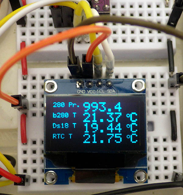 only including the print statements for one line of the the display shown here -> (click to enlarge) but hopefully you see the pattern well enough to lather-rinse-repeat. The pixels do not need to be ‘turned on’ while you load the screen memory, and that data is persistent as long as the screen has power. So if you wanted to tackle more advanced graphic output, you could build plots ‘one line at a time’ in the eeprom without needing a 127 field array to buffer that data.
The TTP223 Touch Switch:

Here I disabled the LED by removing the limit resistor, set the mode to momentary low, and trimmed the header pins so the upper surface is flat. The unmarked solder pads on the upper right are were you would add trimming caps to reduce sensitivity. These switches self calibrate for 0.5 sec at startup, so they need a bit of ‘settling time’ at power-on.
These small capacitive switches can be had for less than ~20¢ each on eBay. The power LED wastes about 8mA, so that needs to be disabled for logger applications. Then you set the operating modes by bridging the A / B solder pads. These switches are so sensitive that moving a finger within 2cm of the surface will trigger them. In applications where the sensor is exposed you probably need to add a 10-20 pF ‘trimming cap’ to prevent self triggering. Noise on your rail can also set them off, and you don’t want loose wires inside the housing near that sensing pad. TTP223 chips do not go rail to rail, but they still work ok driving MOSFETS.
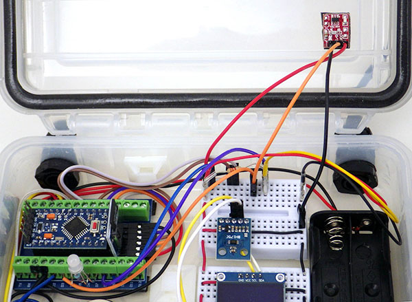
A small square of double sided tape holds the T233 inside the student build just above the batteries. (The outer most rows of the breadboards are power rails)
In our case the sensor will be under 1.5mm of HDPE and another millimeter of double sided foam tape. So the default sensitivity level is almost perfect for sensing through the lid of the housing. With the LED disabled the TTP223 module pulls about 5μA when NOT being triggered, and 100μA when actively signaling the logger. Here I’ve connected the switch using 10cm pre-made jumpers but you want to be careful that you don’t put the switch in a position on the lid where it might cast a shadow over any light sensors as the sun moves through the sky. With our most recent student logger, you also need to shift the indicator led over to R4-GND5-Gr6-Bl7 so that the switch output (orange wire) can be fed into the hardware interrupt on D3. This chip produces ‘clean’ transitions so you don’t need to worry about de-bouncing. These switches seem to work fine without pullup, but I’ve been enabling the internal pull on D3 anyway.
Sensors such as rain gauges generate on/off interrupt signals at any time due to environmental conditions. But no matter how many times that happens, only the RTC’s sampling interval alarm should control the ‘regular’ read cycles in the main loop. To handle multiple interrupt sources we ‘trap’ the processor in a Do-While loop that checks flag variables (set in the associated ISR functions) to see where the wake-up signal originated.
In the code below; if the RTC flag variable is false when the processor reaches the while(flag status check) at the end of the loop, then the program gets sent back to the initial do{ statement. This code assumes you have already programmed the screens memory with data to display:
// when you are about to put the logger to sleep (after setting the RTC alarm)
pinMode( 0, INPUT_PULLUP ); // I always use pin D2 for the RTC alarm signal
rtc_d2_INT0_Flag = false; // D2 interrupt flag – this can only be set true in the ISR
pinMode ( 1 , INPUT_PULLUP ); // Cap. switch output is connected to D3
d3_INT1_Flag = false; // setting false here prevents any display until TTP223 is pressed
EIFR=EIFR; // clears old ‘EMI noise triggers’ on BOTH hardware interrupt lines
do { // The ‘nesting order’ here is critical:
attachInterrupt (1,switchPressed_ISR, FALLING);
attachInterrupt(0, rtc_d2_ISR_function, LOW);
LowPower.powerDown(SLEEP_FOREVER, ADC_OFF, BOD_ON);
detachInterrupt(0); // MUST detach the high priority D2 first
detachInterrupt (1); // then detach the lower priority D3 interrupt
// Here we are simply powering the OLED display pixels but any other code put here
// is isolated from the main sequence, so you could trigger ‘special’ sensor readings, etc.
if (d3_INT1_Flag == true){
oled.ssd1306WriteCmd(SSD1306_DISPLAYON); // turn on the screen pixels
attachInterrupt(0, rtc_d2_ISR_function, LOW);
LowPower.powerDown(SLEEP_8S, ADC_OFF, BOD_ON); // long enough to read
detachInterrupt(0);
oled.ssd1306WriteCmd(SSD1306_DISPLAYOFF); // turn OFF the screen pixels
d3_INT1_Flag = false; // reset D3 interrupt flag
}
} while (rtc_d2_INT0_Flag == false); // if RTC flag has not changed repeat the ‘trap’ loop
if (rtc.checkIfAlarm(1)) { rtc.turnOffAlarm(1); } // processor awake so disable the RTC alarm
EIFR=EIFR; // clears leftover trigger-flags from BOTH D2 & D3
// now return to the start of the main loop & capture the next round of sensor readings
// and each attached interrupt requires an ISR function (outside the main loop!)
switchPressed_ISR() {
if (d3_INT1_Flag==false)
{ d3_INT1_Flag = true; } // Flag variables set in an ISR must be global & ‘volatile’
}
rtc_d2_ISR_function() {
if (rtc_d2_INT0_Flag==false)
{ rtc_d2_INT0_Flag= true; }
}
BOTH the TTP on D3 and the RTC alarm on D2 can wake the logger from sleep – but switchPressed_ISR() does not change the critical flag variable so a wakeup caused by the D3 will not break out of the Do-While loop. Only the rtc_d2_ISR_function() can set the tested flag to true and thus escape from the trap. This general method that works equally well with inputs from reed switch sensors for wind, rain, etc. With a few tweaks the same basic idea can also be used to capture ‘opportunistic’ sensor readings – provided you save those to a different logfile, or tag the ‘extra’ records with something that’s easily sorted from the regular records later in Excel.
Note that the two interrupt sources use different triggers: FALLING for the TTP223, and LOW for the RTC. It doesn’t really affect anything if the switch transition is missed (you can just tap it again), but the whole logger operation is affected if the RTC alarm fails. The RTC must also be able to interrupt the ‘display time’. Fortunately the RTC’s alarm output is ‘latched’ so it will cascade the wake-ups until we exit the do-while loop. The most important thing to know when using HIGH or LOW as your interrupt state is that you MUST detach the interrupt IMMEDIATELY upon waking. If you forget to detach a HIGH or LOW triggered ISR it will just keep on firing until it fills all of the variable memory with stack pointers and crashes your logger.
In addition to preventing the display from using power when nobody is around, having the ability to trigger the display ‘at any time’ is a great way to make sure the logger is OK without opening it – especially if all you want to see is the most recent timestamp & battery level. This is also helpful when students are running labs that can’t be ‘physically disturbed’ ( for example, soil sensors tend to produce significant discontinuities if they get bumped in the middle of a run) Nothing is worse than letting an experiment run for a week, only to find that the system froze up a few hours after it was started.
Handling multiple screens of information
Once you’ve got the basic screen operation working you might want to check our page on using two displays. Keeping each display in different ‘memory access modes’ lets you do some interesting graphical output tricks. But what if you only have one screen and there just isn’t enough room to display everything at one time?
You can use flag variables & switch-case to toggle between different screens of information:
// I use defines in setup{} so the code is more readable, but these are just numbers
#define displaySOILdataNext 0
#define displayTEMPdataNext 1
// set the ‘first screen’ you want to display before entering the do-while trapping loop
uint8_t next_OLED_info = displaySOILdataNext;
do { // our processor ‘trapping loop’ described above
// load the screen’s eeprom at the start of the do-while loop
// each successive press of the touch-switch changes which data gets loaded
switch (next_OLED_info) {
case displaySOILdataNext: // case where next_OLED_info = 0
{
sendSOILdata2OLED(); // a separate function to program the display memory
next_OLED_info=displayTEMPdataNext; //toggles to send different info on next pass
break;
}
case displayTEMPdataNext: // case where next_OLED_info = 1
{
sendTEMPdata2OLED(); // a separate function to load the eeprom
next_OLED_info=displaySOILdataNext; //toggle to opposite screen on next pass
break;
}
} // terminator for switch (next_OLED_info)
{insert here} all the loop content controlling wake/sleep described earlier
} while (rtc_d2_INT0_Flag == false); // end of our processor ‘trapping loop’
// and you will need stand-alone functions for each screen of information:
void sendTEMPdata2OLED() {
oled.clear();
oled.set2X();
oled.setCursor(0,0);
oled.print(TimeStamp+5); // +5 skips first 5 characters of the string because it’s too long
oled.set1X();
oled.setCursor(0,2);
oled.print(F(“Temp1: “));
oled.set2X();
oled.setCursor(46,2);
oled.print(ds18b20_short_degC,2);
// … etc ... add more here until the display is ‘full’
}
void sendSOILdata2OLED() {
oled.clear();
oled.set1X();
oled.setCursor(0,0);
oled.print(F(“RAIL”));
oled.set2X();
oled.setCursor(70,0);
oled.print((float)ads1115_rail*0.000125,3);
// … etc ... add more here until the display is ‘full’
}
The nice thing about this method is that you can toggle your way through as many different screens of information as you need simply by adding more ‘cases’ and screen ‘loading’ functions.
