
Our LED sensor experiments lead to an interesting observation: When these ‘light-sensing’ loggers are left running overnight they still produce readings because reverse-bias ‘leakage-current’ eventually triggers the Interrupt Capture Unit (ICU) – in the absence of any light. The speed of this self-discharge depends on the ambient temperature. If you cover an rgb LED with black heat shrink, the different color channels have different rates of thermal decay:

Temp (Celsius) vs ‘Covered’ LED reverse-bias discharge time (Seconds) , Red, Blue & Green channels, generic rgb LED. The LED was encapsulated in black heat shrink tubing and was connected directly to the IO pins with no limit resistor. LED’s take a very long time to discharge compared to other diodes, so at those time scales you can capture the data with the non-ICU based timing method of simply reading the high/low pin state in a loop. We use that simpler method in the 2019 classroom logger starter code on Github.
Both voltage and temperature affect reverse current, so these measurements must start from from a stable, regulated voltage. Increasing the temperature by almost 20°C reduced the time to 20% of the low-temp value. The green channel appears to be more resistant to leakage which is surprising given that reverse bias currents are usually rated at ~1 µA for RY and ~10 µA for BGW colors. So perhaps this result says more about the volume & surface area of this particular unit than it does about LED color chemistry.
Even if I sleep the processor to save power, multi-minute readings would interfere with the other things we are recording on the Cave Pearl loggers. However, this LED-based approach has interesting applications where space is limited and temps fall within a warmer range. The idea also has a lot of potential in situations that require high levels of sensitivity, although there aren’t many of those that can wait such a long time for readings.
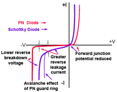 Checking if I could use the technique with other types of diodes led to this jeelabs post where he compares the reverse bias leakage in three common diodes at 5V:
1N4004 – a high power diode: = 1.3 nA
1N4148 – a low power diode: = 3.4 nA
BAT34 – a Schottky diode: = 50 nA
He also had the realization that “the reverse current could even be used as a temperature sensor.” Small diodes have internal capacitance of a few pico-farads, so 5-50 nA will discharge them considerably faster than the LED channels I was using. In fact, reverse leakage increases so much with Schottky diodes it can cause a thermal instability issues which limit their useful reverse voltage to well below their max rating. Germanium Diodes are even more susceptible.

Add black heat-shrink around diodes with clear encapsulation (like the one shown here) or they will also be affected by light levels in the local environment.
It’s worth noting that most diode based temperature sensors use the change in forward voltage because that relationship is linear, with about 2mV less voltage drop for every degree increase of temperature. But chasing a few milli-volts with Arduino’s 10-bit ADC only allows a precision of ±1°C unless you add amplification, or some other trick.
By comparison, leakage current can be expected to double with every 10°C increase in temperature, making higher resolutions possible with the same hardware. The trade off is using a non-linear relationship which produces variable resolution over the sensing range. And since leakage is also a byproduct of manufacturing variations you need to calibrate each diode individually. That’s a show-stopper in production environments where that time costs more than the whole device, but not so much for DIY projects which need to run-test their build for a few days anyway. We don’t usually send a logger into the field until it’s had several weeks of stable operation.
Testing a 1n5819 Schottky Diode:
Here I’m timing the leakage-discharge with Timer1 clock ticks from an 8mHz 3.3v ProMini:

Temperature (°C) vs 1n5819 Shottky Reverse-bias Leakage Discharge Time (8 mHz clock cycles) Diode connected between D7 & ICU on D8. Blue dots are Excel’s trend-line. That fit was better than I was expecting.
The Schottky discharges very quickly at room temperatures, with raw Timer1 counts of about 1300 at room temperature ( ~0.16 milliseconds) and about 100 counts of variation /°C. Counts increase as temperature falls to ~5800 ( ~0.7 ms) at 6°C, with a delta of 580 counts per degree. The curve flattens out at the lower limit of this test with raw counts about 62,000 ( ~7.7 ms) at -15°C, and a delta of 7000 counts/degree.
The timing jitter on these ICU readings ranges between 10-20 counts depending on the board (even with 4x noise reduction enabled) and this is a significant source of error when you only have a per-degree delta of 100 counts. You can over-sample the Schottky to compensate, and testing showed that 256x OS readings produced results that looked very comparable to 1n1418 diodes. (although some authorities say that timing-jitter may be resistant to this smoothing technique.) Even with oversampling, these short discharge times could become too brief to even count with an 8mhz Promini at temps above 50°C. However measuring cold temperatures can sometimes be more challenging than warm ones, and for those applications a fast discharging diode like a Schottky might be preferred. With communications overhead, it’s not unusual for an I2C sensor reading to take 1-2ms, so a Schottky might also be better for low power systems trying to minimize CPU runtime.
Testing a 1n4148 Signal Diode:

Temperature (°C) vs 1n4148 Reverse-bias Leakage Discharge Time (8 mHz clock cycles) Diode connected between D7 & ICU on D8. Diode wrapped in black heat shrink tubing. Blue dots are Excel trend-line fit.
The 1n1418 discharges more slowly, with raw Timer1 counts of about 36,000 at room temperatures (~5 msec.), and about 2000 counts of variation/degree at 25°C. Raw counts increase to ~158000 (~20 ms) at 6°C, with a delta of ~17000 counts per degree and the lower limit of this test saw raw counts 1.3 million (166 ms) at -15°C, and a delta of 140,000 counts/degree.
The 1n1418 is better sensor overall because it won’t drop below the Arduino’s timing capability at natural environment temperatures, and it’s discharge takes long enough that jitter becomes an insignificant source of error. Even in colder environments, 166ms of SLEEP_MODE_IDLE (which leaves Timer 1 running for the clock cycle count) only burns about 0.16 milliamp-seconds per reading on a Promini. That’s not going to break our power budget.
Calibration:
Its worth noting again that you must use a regulated system. Ideally, shifting supply voltage causes a corresponding change to the Schmitt trigger points on the I/O pins. That compensates to some extent, however batteries have significant thermal mass and this causes serious hysteresis problems when sensing temperature.
To calibrate my diodes, I covered them with black heat shrink tubing and taped them in physical contact with an si7051 sensor. Then I placed the logger into a rice filled double ceramic pot ( to add thermal mass) and moved the pot around the kitchen, from the radiators to the refrigerator & freezer. You want stable periods that let the ref & diode sensors equalize, using an average of 20 readings to smooth compressor wobble at the lower end, and those crest/peaks at higher temperatures.
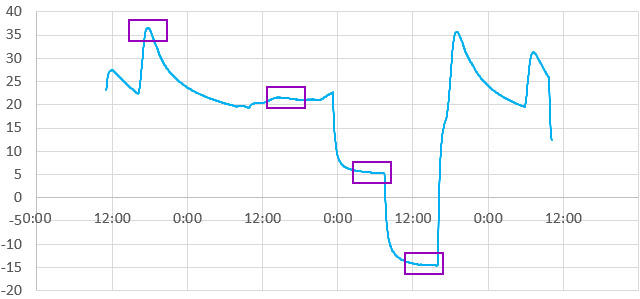
Typical SI7051 (±0.1°C) reference temperature run for calibrating the 1n1418 diode. Boxes indicate plateaus chosen for the calibration data points & coverage areas of closeup graphs shown in the ‘sets’ comparison below.
Excel trend-lines got reasonably close to the response from the Shottky & 1n1418; perhaps needing only one more term for a better fit. Since thermistors are also semiconductor devices I wondered if those diode decays would generate workable S&H constants if I treat the raw Timer1 counts AS IF they were resistance values from an NTC:
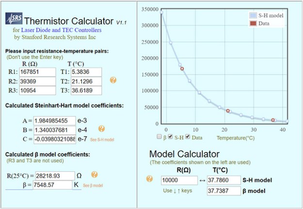
Here I used 20 reading averages to compensate for the fact that the diode is higher resolution than the Si7051 reference, and the long-integration 1n1418 readings have considerably less jitter than the IC sensor.
Then you can convert the discharge time to temperature with the Steinhart-Hart equation:
#define COEFF_A 2.0007E-03 // Coefficient from SRS online calculator
#define COEFF_B 1.3166E-04
#define COEFF_C 3.5441E-09
float Temp = log(RawDiodeDischargeTime); // note that Log(x) on Arduino is actually LN(x)!
Temp = COEFF_A + (COEFF_B * Temp) + (COEFF_C*(Temp*Temp*Temp));
Temp = (1 /Temp) -273.15; // -273 converts Kelvin to Celsius
(Note: I usually save raw readings on the loggers & convert them later in Excel. I’ve been burned several times by loss of significant figures during calculation on the 8-bit 328P processor)
That equation has a quoted accuracy of about ±0.1°C over a 100 degree range when used for a thermistor, but does this hold with a diode sensor? Yes – but over a smaller 40 degree range: (Click Image to Enlarge)
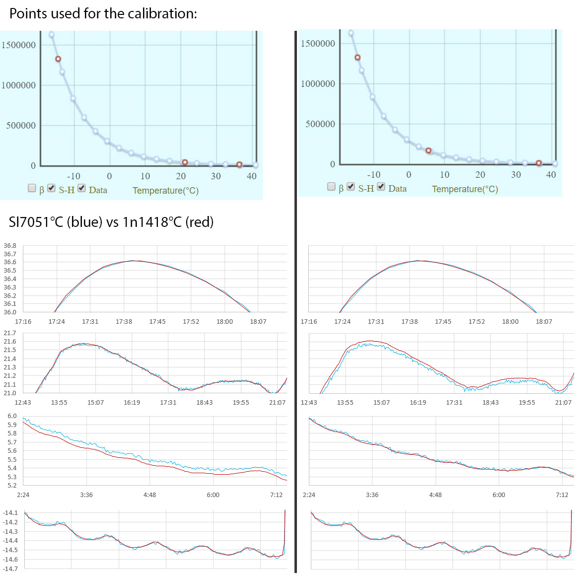
Comparison of si7051 reference temps (blue) (°C) vs 1n1418 based S&H calculations (red) Two examples shown with different ‘center’ points (21°C on the left & 5°C on right) used to generate the three equation constants.
I choose these sets to show calculation errors creeping in as you move farther from the points used to generate the constants. The calculated temperatures in this example drift ~0.07°C from the reference at a distance of ~15°C from the center point. A tighter set with calibration points at 5, 21, & 36°C produces a near-perfect fit inside that range, with the trade-off that temps down at -14°C then show an increased deviation >0.1°C. Overall, it’s about 30% more error than I’d expect to see when calibrating a cheap 10K thermistors with the same points. Given that our Si7051 reference thermometer has a rated accuracy of ±0.13 °C (datasheet pg 7), I think the best we can achieve for this diode based method is ~±0.2 °C at typical cave temperatures.
So max-middle-min gives you about 40 degrees of usable range and you want at least one of your cal. points at the area of interest. That’s pretty good considering we are applying the thermistor equation to a different physical system. I will experiment with solver to see if models with more parameters provide a better fit, but this is already is good enough for most of our logger deployments.
Figure 14-1 I/O Pin Equivalent Schematic from the 328p datasheet. Those protection diodes can also cause problems when de-powering voltage dividers.
My gut feeling is that the re-purposed equation would work over a wider range if this was a single diode system. However AVR inputs are also connected to two protection diodes and a pull-up MOSFET. Each of these is subject to its own reverse bias leakage to some extent, with the upper protection diode acting in direct opposition to the discharge of the ‘sensor’ diode. In fact, you can simply run the ICU timing code with nothing at all connected to the D8 pin, and it will still give you a temperature based reading. That makes this the second ‘no parts temperature sensor’ method I’ve discovered for Arduino but, like LED’s, these diodes are low leakage; taking five seconds for a read at 20°C, and five minutes for a reading down at -14°C. Unless you change the prescaler, the raw numbers could exceed the range of easy calculation on a 328, and show significant hysteresis due to the mass of the chip & Promini board it’s attached to.
The implication here is that temperature sensing via this reverse bias decay method has a sweet spot somewhere between the too-rapid response of a Shottky diode (which approaches the counting limits of an 8MHz clock) and interference from the other stuff connected to Arduino I/O pins. 1n1418’s work well, but I’m sure there are other diodes out there that could do a better job. I have yet to find any good data on the long term stability of reverse bias leakage but we are not stressing the part by exceeding it’s reverse voltage rating, or running enough current to cause much self-heating. So I suspect that diode leakage is at least as stable as thermistor response over time. There’s a lot of further experimentation to do here, and given the tighter manufacturing spec, I’m curious to see if the method works with diode connected transistors which could make interchangeable temperature sensors possible.
I should also mention that some ‘better quality’ Arduino boards have temperature compensation embedded in their system oscillator. This is a bad thing for this ICU timing method because it introduces a sharp discontinuity in the clock speed when the comp. circuitry kicks in. The S&H constants can’t absorb that like the normal ‘thermal response’ of a cheap oscillator, so the method works better on some boards than others. Another potential problem is moisture accumulating on surfaces -which could provide an alternate current path to discharge the diode. So as with our LED light sensing, desiccants are required inside the logger housing.
the CODE:
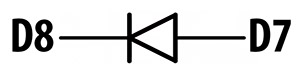
D7 is simply acting as a convenient GND connection.
I’ve left this till last, because it’s essentially just a tweaked version of the ICU timing method I posted for reading thermistors. With the diode discharge you triggering on fall instead of rise, and you don’t have to read a reference resistor because we are treating the decay time as a resistance. The diode’s tiny internal capacitance charges through the INPUT_PULLUP resistor in a few nanoseconds, and there’s no need to discharge afterward.
(Note: This code is modified from the ICU capacitor reading example by Nick Gammon)
#include <avr/power.h> // for peripherals shutdown
#include <avr/sleep.h> // to sleep the processor
volatile boolean triggered;
volatile uint16_t timer1CounterValue;
volatile uint16_t overflowCount;
ISR (TIMER1_OVF_vect) { // triggers when T1 overflows: every 65536 system clock ticks
overflowCount++;
}
ISR (TIMER1_CAPT_vect) { // transfers Timer1 when D8 reaches the threshold
if (triggered){ return; } // multiple trigger error catch
timer1CounterValue = ICR1; // Input Capture register (datasheet p117)
triggered = true;
if ((TIFR1 & bit (TOV1)) && timer1CounterValue < 256){ // 256 is an arbitrary low value
overflowCount++; // if “just missed” an overflow
}
bitClear(TIMSK1,TOIE1); // disable interrupts on Timer 1 overflow
bitClear(TIMSK1,ICIE1); // disable input capture
}
void prepareForInterrupts() {
noInterrupts ();
triggered = false; // reset for the do{ … }while(!triggered); loop
TCCR1A = 0; // set entire TCCR1A register to 0
TCCR1B = 0; // same for TCCR1B
TIFR1 = bit (ICF1) | bit (TOV1); // clear flags so we don’t get a bogus interrupt
TCNT1 = 0; // initialize counter value to 0
overflowCount = 0; // reset overflow counter
bitSet(TCCR1B,CS10); // set prescaler to 1x system clock (F_CPU)
bitSet(TIMSK1,TOIE1); // interrupt on Timer 1 overflow
bitSet(TCCR1B,ICNC1); // Input Capture Noise Canceler = 4x repeat b4 trigger
bitClear(TCCR1B,ICES1); // Input Capture Edge Select ICES1: =0 for falling edge
// or use bitSet(TCCR1B,ICES1); to record rising edge
bitSet(TIMSK1,ICIE1); // Enable input capture unit
TIFR1 = bit (ICF1) | bit (TOV1); // clear flags again ( this may be unnecessary?)
interrupts ();
}
//========== READ DIODE connected between D7 —>|— D8 ICU ===========
digitalWrite(7,LOW); pinMode(7, OUTPUT); // simply acting as GND
digitalWrite(8,LOW); pinMode(8,OUTPUT);
power_timer0_disable(); // otherwise Timer0 generates interrupts every 1us
power_timer1_enable(); // this whole method depends on timer1
bitSet(ACSR,ACD); // Disable the analog comparator
//could disable other peripherals to save power during idle
digitalWrite(8,INPUT_PULLUP); // charging the diode-capacitor (occurs VERY quickly) prepareForInterrupts ();
noInterrupts ();
set_sleep_mode (SLEEP_MODE_IDLE); // leaves Timer1 running
sleep_enable();
PORTB ^= B00000001; // toggles OFF pull-up resistor on D8 (leaving pin in INPUT)
TCNT1 = 0; // re-initialize Timer1 counter
do{
interrupts ();
sleep_cpu (); //sleep until D8 falls to the 33% threshold voltage
noInterrupts ();
}while(!triggered); //trapped here till TIMER1_CAPT_vect sets triggered=true
uint32_t diodeDischargeTime= ((uint32_t)overflowCount*65535) + timer1CounterValue;
// change to uint64_t calculations when timing diodes that decay slowly
sleep_disable();
interrupts ();
power_timer1_disable(); // cleanup
power_timer0_enable(); // needed for delay, micros, etc.
(Note: Integer arithmetic on the Arduino defaults to 16 bit & never promotes to higher bit calculations, unless you cast one of the numbers to a high-bit integer first. After casting the Arduino supports 64-bit “long long” int64_t & uint64_t integers for large number calculations but they do gobble up lots of program memory space – typically adding 1 to 3k to the compiled size. Also Arduino’s printing function can not handle 64 bit numbers, so you have to slice them into smaller pieces before using any .print functions)
Addendum 2021-01-24 Don’t sleep with regular I/O pins.
I’ve been noodling around with other discharge timing methods and come across something that’s relevant to using these methods on other digital pins. Here’s the schematic from the actual 328 datasheet, with a bit of highlighting added. The green path is PINx. It’s always available to the databus through the synchronizer (except for in SLEEP mode?) The purple path is PORTx. Whether or not it is connected to PINx depends on the state of DDRx (which is the yellow path.)
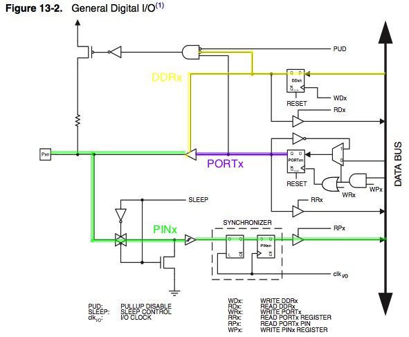
As shown in the figure of General Digital I/O, the digital input signal can be clamped to ground at the input of the Schmitt Trigger. The signal denoted SLEEP in the figure, is set by the MCU Sleep Controller in Power-down mode and Standby mode to avoid high power consumption if some input signals are left floating, or have an analog signal level close to VCC/2.
When sleeping, any GPIO that is not used an an interrupt input has its input buffer disconnected from the pin and in clamped LOW by the MOSFET.
Clearly D8 on the ICU must one of those ‘interrupt exceptions’ or the thermal discharge of the diode would have been grounded out by entering the sleep state. If you use a similar method on regular IO pins you can’t sleep the processor in that central do-while loop.

I love it when you dig in to the nitty-gritty of calibration and stability issues and (with luck) can pull out other environmental variables. But one thing that’s made me cautious so far has been the observation that the reverse-biased diode (or LED) needs to be very close (directly connected) to the Minipro to avoid cable capacitance issues (and there are already a variety of temperature sensors -on- the MiniPro/CavePearl build in one form or another). But with the “too fast” leakage behavior of the Schottky makes me wonder what would happen if I took advantage of the added capacitance of a longer connected cable to slow the response. That could enable slightly more remote (at least out of the housing) temperature sensors. Yes, it means you’re hanging about waiting longer for the sensor return… but high resolution, very slow temperatures sensors are handy for some things (like… well, caves 🙂 )
Yeah, I’ve noted before that the discharge technique does not like breadboards because of the capacitance that those flaky connections add at random to the system. But wire length is much less of a problem so long as it remains consistent (twisted pair cables?) between the calibration and the data gathering. And the 1n1418 is small enough to solder right to the header pins in a tight build.
I’ve been working on my ICU chops specifically for those ‘other environmental variables’, but temperature just keeps falling into my lap as a by-product. I guess that’s not really surprising, given that at some level, every sensor is a temperature sensor.
Interestingly reverse ‘saturation’ current is the dominant factor even if you are measuring the diodes forward voltage. So I have a sneaky suspicion that I might be able to come up with an ICU based alternative to the standard ΔVbe methods. Need more head scratching time for that one though…
Pingback: Use a Single Diode as a Temperature Sensor with Arduino ICU – Arduino Apprentices
With comms overhead, its not unusual for an I2C sensor reading to take 1-2ms at 100mHz,
Is that a typo –100 milli Hz? I’d say it is unusual if not.
Oops! Thanks for catching that. I meant the 100 KHz default speed for the I2C bus. (post has been updated)
Pingback: Single diode temperature sensor with Arduino ICU (& reverse-bias leakage) – gStore
Can this trick be applied to led on D13?
It’s wired so that the LED runs current ‘forward’ to light when pin13 is high. In order to use that LED as a sensor you would need to flip it around so that it would be in ‘reverse’ bias mode, and charge up it’s internal capacitance when D13 is high. Which you could do, but then it would no longer be usable as an indicator since the other side of that circuit is GND. You’d also have to lay down a blob of black epoxy over it to keep it from reacting to light, since the photon decay is usually much faster than the thermal decay.
Pingback: A single diode temperature sensor with Arduino #Arduino #Temperature #Sensors @CavePearlLog « Adafruit Industries – Makers, hackers, artists, designers and engineers!