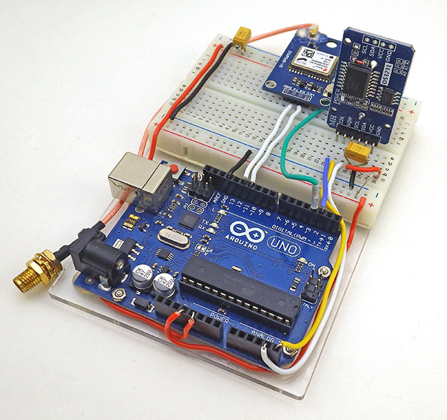
I’m developing a family of environmental monitors for use in caves and underwater, but the basic three component logger platform will support a wide range of different sensors.
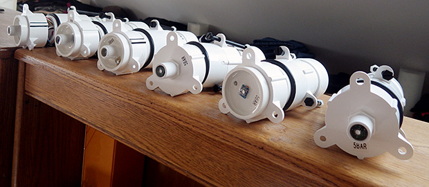
The next generation of flow sensors running “hang” tests so I can quantify sensor mounting offsets. I like to see a few weeks of operation before I call a unit ready to deploy. Each new batch suffers some infant mortality after running for a few days.
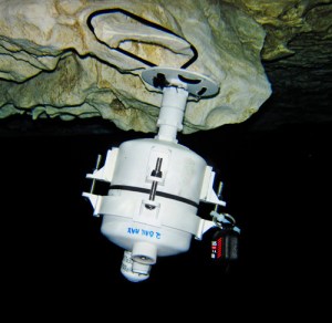
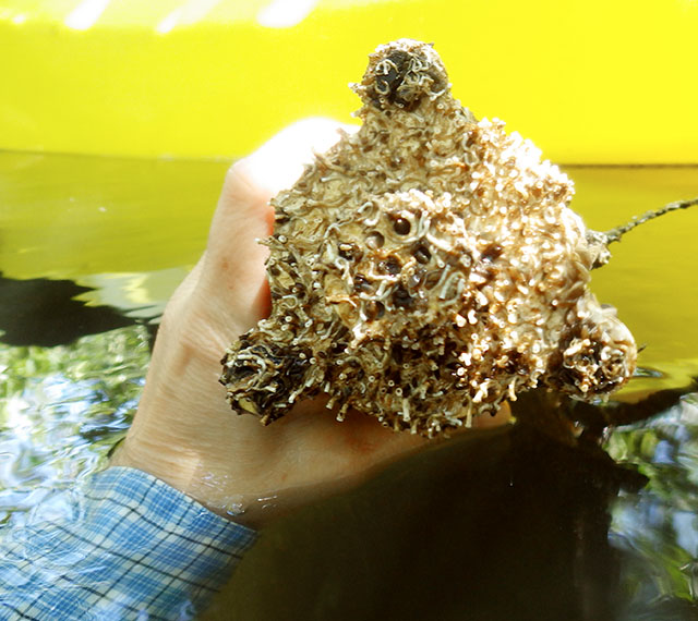
I’m finally getting the next generation of Pearls together for their pre-deployment test runs. The new underwater units will all be in 2″ enclosures and perhaps it’s just me, but I think the slimmer housings make them look more like professional kit. These units are larger than I would have liked, but with six AA batteries they needed some extra air space to achieve neutral buoyancy. With the slow but steady improvements to the power consumption, this might be the last batch designed to carry that much juice. There are a host of other little tweeks including new accelerometers because despite all the hard work it took to get them going the BMA180’s did not deliver the data quality I was hoping for. It would seem that just having a 14bit ADC does not always mean that the sensor will make good use of it. This is the first generation of flow sensors that will be fully calibratedbefore they go into the field. That’s important because most of these guys will be deployed in deeper saline systems with flows slower than 1 m/s.
This is a sensor cap for the Masons hygrometer experiment which uses waterproof DS18B20s for the wet & dry bulb readings, with the extra sensor letting me compare different drip sources simultaneously. An MS5803-05 records barometric pressure, and I put a (redundant) MCP9808 in the leftover sensor well to track the housing temperature.
A new crop of drip sensors is ready, and this time a couple of them will be based on the Moteino Mega, with a 1284 mcu providing lots of SRAM for buffering. They performed reasonably well on bench tests but it will be interesting to see how they fare in the real cave environment. The drip loggers we left on the surface as crude rain gauges will be upgraded with protective housings and catchment funnels, hopefully providing a more accurate precipitation record. They will be joined at the surface by new pressure/temp/r.h. loggers that sport some DIY radiation shields and they will have none of the Qsil silicone which swamped out the barometric readings with thermal expansion last time.
A bit of shoelace becomes a wick for the wet bulb. It’s made from a synthetic material, as I suspect that the traditional cotton wicks would quickly rot in the cave.
And we will have a couple of new humidity sensors to deploy on the next fieldwork trip. The rapid demise of our HTU21D’s back in December prompted me to look for othermethods that would survive long periods in a condensing environment. That search lead me to some old school Masons hygrometers, which in theory let you derive relative humidity with two thermometers provided you keep one of them wet all the time so that it is cooled by evaporation. The key insight here is that I am already tracking drip rates, so I have a readily available source of water to maintain the “wet bulb” for very long periods of time. If the drip count falls too low I will know that my water source has dried up, so I will ignore the readings from those times.
Underwater deployments have already proven that the MS5803 pressure sensors are up to the task and waterproof DS18B20s look like they might have enough precision for the job. The relatively poor ±0.5°C accuracy of the DS18’s does not matter so much in this case as the “wet bulb depression” is purely a relative measurement, so all you have to do is normalize the sensors to each other before deploying them. I still had a few closely matched sets left over from the temperature string calibrations, so I just used those.
This RH sensor has a copper sintered mesh, and all the non-sensing internals are coated with silicone. It’s worth noting that the SHT series does not play well with I2C sensors, and must have it’s own set of dedicated com pins. It also pulls far more current than the datasheet says it should, so this logger draws a whopping 0.8mA while sleeping. I’m driving it with the library from practical arduino’s github, so perhaps something in there is preventing the SHT11 from sleeping(?)
Of course there are a host of things that I will be blatantly disregarding in this experiment. For starters you are only supposed to use pure distilled water, and cave drip water is generally saturated by its passage through the limestone. Perhaps the biggest unknown will be the psychrometric constant, which changes pretty dramatically depending on ventilation, and with several other physical parameters of the instrument. Since there is no way I am going to derive any of that from first principles, I though I would try a parallel deployment with a second humidity sensor so I could determine the constant empirically. The toughest looking electronic R.H. sensor I could find for this co-deployment was the soil moisture sensor from Seeed Studios. Even with it’s robust packaging, I expect it to croak after a few months in the cave, but hopefully the SHT11 will give me enough data to interpret the readings from the other hygrometer.
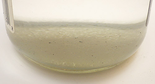
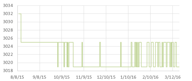
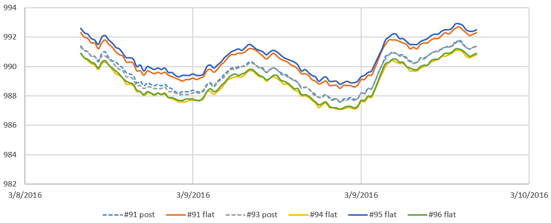
Once the epoxy had cured, I set the two units up in the furnace room so the wet bulb was not ventilated. Recent heavy rains meant our basement was hitting 75% RH, and I had a dehumidifier running at night to pull that down to 55%. (far from the Masons so there was no air movement at the wick!). That test produced wet-bulb depressions between 2-4 degrees Celsius, allowing me to create the following graph:
Even with the psychrometer constant bumped up to 0.0015 (0.0012 is usually quoted for non ventilated designs with warnings that the number will be different for each instrument)the Mason is reading about 10-12% above the SHT11. I can deal with that if the offset is constant, but it means that the difference between the two bulbs is smaller than it should be. That is typically the direction of errors for this kind of design but when the humidity gets up into the 90’s, my humble DS18’s might not have enough resolution to discriminate those small differences – especially if there is some ugly non-linear compression happening.You can already see some of that digital grit showing up on the green plot above. I was pleasantly surprised to see very little difference in the response time for the two sensors, although I suspect that is because they both have significant lag.
For a first run, those curves match well enough that the method is worth investigating. We can put up with lower resolution & a lot of post processing if the sensor will operate reliably in the cave environment for a year. And if the idea doesn’t work I will still be left with a multi-head temperature probe, which can be put to other good uses. I will build a couple more of these, and keep at least one at home for further calibration testing.
Addendum 2015-07-21
I did not use distilled water in those reservoirs, as the cave drip water will have plenty of dissolved solutes which will shrink the wet bulb depressions
I set up the new hygrometer caps for a long run in an enclosed storage space under the porch; which is the closest thing I have to an unventilated cave environment. Fortunately the weather obliged with a good bit of rain during the test, pushing the relative humidity up towards the 90’s where the loggers will be spending most of their time after they are deployed. These builds include pressure sensors, but the one I will be keeping at home also has an HTU21D R.H. sensor, since the SHT-11 I am using as my primary reference will go into the field.
Readings from the HTU21 vary between 4-6% lower than the SHT-11:
So as usual, having multiple sensors to read RH directly puts me back into “the man with two watches” territory; though I have slightly more faith in the Sensirion. If I match the overall dynamic range of the Mason output to the soil moisture sensor by tweaking psychometric constants, I can bring the them within 3.5% of the SHT (with uncorrected R-squares > 0.93) :
I was hoping that those psychometric constants would be much closer to each other and I will have to chew on these results to see if I can figure out what is causing the variance between the instruments. I would also like to know where that positive 3.5% offset comes from.
I should mention here that a similar offset problem affects the atmospheric pressure sensors which I need to calculate the actual water vapor pressure using:
Fortunately at weather.gov they post three days of historical data from your local NOAA weather station, which you can use to find the offset for your home built pressure sensors:
(Note:I had to concatenate the date/time info into Excel’s time format to make this graph)
Most of my MS58xx sensors seem to have a -10 to -20 mBar offset after they are mounted. I suspect that this is due to the epoxy placing strain on the housing because of some shrinkage while curing. Overall variations in air pressure have a small effect on the calculation, and many wall mount hygrometers don’t even specify corrections for elevation. So you could probably use this method reasonably well without a “local” barometric sensor by just putting 101.3 kPa in the calculation.
Addendum 2015-07-22
I just stumbled across a neat soil moisture sensor project, that measures moisture dependent conductivity through some Plaster of Paris in a straw. I’m not sure it would give me the durability I need for long cave deployments but it still looks like a great DIY solution. It would be interesting to see how they compare to the commercial gypsum based sensors which usually run around $40 each.
A helpful comment over at the Arduino.cc sensors forum put me onto this tutorial. I did not know that the meat & dairy industry is still using wet & dry bulbs to monitor R.H. so I have a new place to look for information on the method. There is another document over at Sensors Magazine at Sensors Magazine outlining how a thermistor pair can be used to determine humidity if one is hermetically encapsulated in dry nitrogen and the other is exposed to the environment. You drive current through the sensors to produce self heating, and then measure the differential cooling rates of the dry nitrogen vs exposed sensor to derive the humidity.
Addendum 2015-08-14
Two Masons Hygrometers are now deployed in Rio Secreto cave next to my drip loggers: (I will keep the third one at home for further testing)
This unit has the two dry bulb probes suspended in air with cable ties, while the wet bulb is fed by runoff from a drip station. I tried to choose a station that does not run dry at any time through the year.
It will be at least four months before we pull these units and find out if the experiment worked. Fingers crossed!
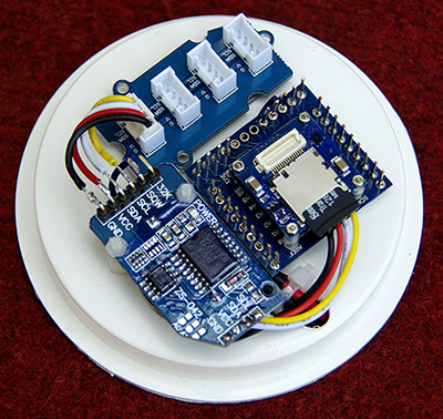
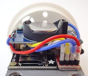
Typical “dry” cave logger platform with a Groove I2C hub to interconnect the individual sensors.
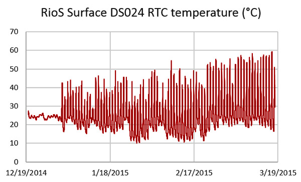
Reliable climate records can be hard to find for some areas, especially with the significant local variability you see in tropical locations. But it is important for understanding the hydrology of the caves so as I rebuilt the Pressure and R.H. loggers following the ECL05 epoxy failures, (I’m trying out some urethane this time round…) I thought a bit more about putting together a logging weather station. The temperature record from the “naked” drip counter we installed during the last deployment hit almost 60°C, which fried the SD card controller. This made it clear that any sensors on left on the surface need decent protection from the sun. A full Stevenson Screen is impractical to transport, and the smaller pre-made radiation shields seem unreasonably expensive for what they are (~$100 ea). Since I still don’t have a 3D printerto play with, I cobbled one together from dollar store serving plates and nylon standoffs which thread directly into each other; making it easy to add as many layers to the shield as you need. The trick is finding dishes made from flexible plastic like polyethylene that is easy to drill; polystyrene tends to be brittle and cracks when you try to make the large central hole. Even with a $6 can of spray paint thrown in, these shields only cost about $10 each, but I will try to find plates that are white to begin with for the next builds:
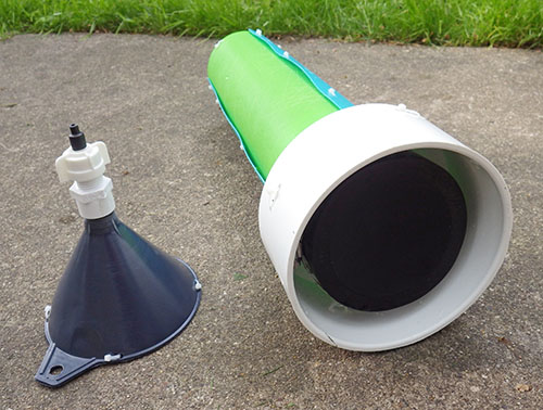
The cave drip sensors fit nicely into a 4-6 inch coupling adapter. The funnel uses a pex adapter so that I can change/replace the drip tips as I look for the best size to use. (currently 5.0mm heatshrink)
With temperature, pressure and relative humidity in hand the next task was to convert my cave drip counters into recording rain gauges. Earlier sensor calibrations had shown me that nozzle diameter was the key to consistent drip volumes, and I modified a funnel with some heat shrink tubing to yield a smaller 5mm tip. A large sewer pipe adapter provides a heavy stable base, offering the necessary sun protection and allowing me to add some inclination so the sensor sheds water from the impact surface.
One unit has a riser tube made from Ikea cutting mats so that it will “flat pack” nicely into the suitcase. I will extend the tube to raise the catchment funnel if I can source parts locally.
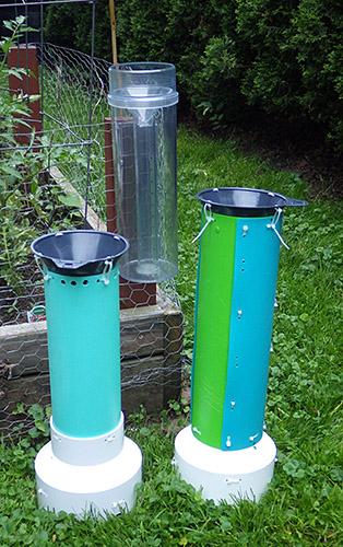
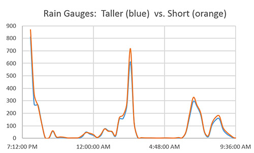
A riser tube then holds the catchment funnel sufficiently far away that the drops gain some momentum and these funnels do a good job of converting fine misty rains into drops big enough to trigger the sensors. As usual, everything is held together with cable ties so that it can be disassembled for transport. I picked up an old school Stratus rain gauge to calibrate the loggers and set everything up in the back yard just in time to catch a few summer thunder storms. Ideally these gauges would be up off the ground, out in an open field, but my yard has few areas that are not directly covered by trees. I also noticed that high winds can sometimes shake the units enough to create false positives, so I now anchor the bases to cement blocks. Even with these sub-optimal factors, these loggers report within 10% of each other. Not USGSquality yet, but I am happy with them as prototypes. I will add a larger 8′ funnel later, to bring the loggers in line with NOAA standard rain gauges.
A subset of data from one of the calibration runs with the count binned at 15 minutes. Thirty one millimeters of rain fell during this test and the nozzles are producing between 12-13 drops per mL of water. Differences between the funnel tips become more pronounced at the higher rates.
Wind is the next piece of the puzzle, and I still have to choose which way to go for that. Some brave souls DIYtheiranemometers with hard disk motors, mouse scroll wheelencoders, or salvaged optocouplers & roller blade bearings. But my gut feeling is that achieving linear-output is non-trivial exercise even if you can just print out the vanes. There are plenty of cheap “rotating egg cup” sensors to be had for as littleas $20 and I would gladly pay that just to know the calibration constant(which you need to convert those rotations into actual wind speed). These cheap sensors are used in the Sparkfun kit and have simple reed switches. It should be easy to convert those switch closures to interrupts or to pulse counts, which my drip loggers could record provided I can debounce them well enough. I tried this approach before when I was evaluating shake switches for the early drip sensor prototypes. Although I rejected those sensors (because they kept vibrating for too long after each drip impact) they did work with essentially the same code that supports the accelerometer interrupts.
And there are other options: Modern Devices has a thermal loss sensor that looks interesting because it has no moving parts and is sensitive to very low wind speeds. A few of the more serious makers out there have builtultrasonicanemometers, which are some of the coolest Arduino projects I’ve ever seen. But even if I could do a build at that level I’m not sure it would be a good idea. As soon as something stops looking like a “cheap hunk of plastic” and starts to look like an actual scientific instrument (as those ultrasonics do) , it draws a bit too much attention for unsupervised locations.
Wind direction sensors often use reed switches & resistors, and that should be easy enough to sort out by reading voltages on an analog pin. The key would seem to be pin powering the resistor bridge only at read time (using a 2n7000 mosfet) so that you don’t have voltage dividers draining the battery all the time. For both wind sensors there will be some questions for me to sort out about circular averaging those readings in a meaningful way.
My first builds will have a separate logger dedicated to each sensor since the loggers are less than the cost of the sensors anyway. The wireless data transmission that most weather stations focus on is not as important to this project as battery operated redundancy. But I can see the utility of separate sensor nodes passing data to a central backup unit so that might spur me to play with some transceivers.
Addendum 2015-07-22
During outdoor tests some of the the small grey catchment funnels became plugged up with leaf litter. Since I needed a larger diameter catchment funnel to conform to the NOAA standards anyway, I found an 8 inch nylon brewing funnel on ebay that had an integrated strainer, and set up another comparison test in the back yard. I left the units running for almost two weeks and nature obliged with a few good rain storms to give me a decent data set.
Water standing on the nylon filter screen. I added several larger holes after discovering this.
Fences and trees surrounding my backyard mean that the location was likely to produce significant variability, and I saw almost 15% difference between the two loggers with the large funnels, with most of that showing up during the peak rainfall events which suffered the effects of wind going around the nearby trees. I standardized the drip tips to 6 mm with heat shrink tubing, but I will still have to do more indoor tests to determine if other factors, like accelerometer sensitivity, might also be contributing to this variability (and keeping in mind that it’s not unusual for consumer units to see >5% variability even under idea conditions). With the Stratus as my reference, the new loggers were seeing between 3-4 drips per ml of captured rainfall. That’s larger than the 0.25 ml drip volume asymptote listed by Collister & Mattey, which made me suspect the units were under reporting. Further tests revealed that the new filter screens are so hydrophobic that they suspended a significant volume of water, no doubt holding it there long enough to evaporate. Argh!
Addendum 2015-12-08
Our first real world deployment of the rain gauges gave us some excellent data from Rio Secreto.
Addendum 2016-12-20
One of our drip counter rain gauges going head to head with an old Met1. This site gave us solid calibration data with overall counts about 20% lower than my home calibrations. So we have some significant (evaporation?) losses in this real world environment, leading to under reporting.
In the mean time we are making due with cement blocks; tucking pressure, temp & RH loggers inside the hollow channels. Over time I’ve been lowering the sensitivity of the accelerometer to reduce the spurious counts from wind noise, which has turned out to be the Achilles heel of this method for measuring rainfall. Dual deployments with trusted gauges is getting us closer to settings which will keep that under control. One of the cool things about these tests is that the loggers are running exactly the same code for both the accelerometer and for the traditional tipping bucket gauge: in both cases it’s simply an interrupt counter, with a longish sleep delay for de-bouncing. A lot of wind speed sensors use the same reed switch mechanism at the met. rain gauge, but a standard promini only has two hardware interrupts, so either I give each device its own logger (for high redundancy) or I dig into pin change interrupts to connect more than one of these sensors to the same logger.
Some use the internal pull-up resistors to connect sensor reed switches directly to Arduino pins, but for a few penny parts, I figured it was worth adding 5-10ms of hardware de-bouncing before attachInterrupt(1, rainInterruptFunc, LOW); Most of the rain gauges I checked listed reed switch closures of ~130ms, & bounce times of ~1ms. But if you work backwards from the max.range numbers, few list accuracy specs for rainfall causing more than 2-3 bucket tips per second.
And I’ve given up on plastic Stevens shields shown above. The local varmints used them as chew toys, busting the all the struts. There are some really cheap solar shields are now popping up for ~$10USD anyway. The nylon funnels have also been taking a beating under the tropical sun, so I am scouting around now for good aluminum or stainless funnels to replace them. The key there is to make sure they have good integrated screens made of metal so that they stand up to the U.V.
Addendum 2017-02-08
Just stumbled across this Humidity sensor shootout by kandersmith, along with a brilliant example of humidity sensor calibration work. The Bosch BME280 won easily as the most accurate. I also found this video about the TAHMO weather station, which is probably the sweetest sensor combination unit I’ve ever seen. And after seeing all that elegant work, I have to throw in a link to this perfboard monster over at the Louisville Hacker space; just to balance your weather station karma 🙂
Addendum 2017-05-08
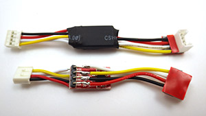
IP68 2-way and 3-way junction boxes have recently fallen below $3 on ebay. My DIY waterproof connectors are more robust, but for quick connections to weather sensors, these cheap pre-made junctions might also do the trick.
Abstract:Existing methods for dynamic calibration of tipping-bucket rain gauges (TBRs) can be time consuming and labor intensive. A new automated dynamic calibration system has been developed to calibrate TBRs with minimal effort. The system consists of a programmable pump, datalogger, digital balance, and computer. Calibration is performed in two steps: 1) pump calibration and 2) rain gauge calibration. Pump calibration ensures precise control of water flow rates delivered to the rain gauge funnel; rain gauge calibration ensures precise conversion of bucket tip times to actual rainfall rates. Calibration of the pump and one rain gauge for 10 selected pump rates typically requires about 8 h. Data files generated during rain gauge calibration are used to compute rainfall intensities and amounts from a record of bucket tip times collected in the field. The system was tested using 5 types of commercial TBRs (15.2-, 20.3-, and 30.5-cm diameters; 0.1-, 0.2-, and 1.0-mm resolutions) and using 14 TBRs of a single type (20.3-cm diameter; 0.1-mm resolution). Ten pump rates ranging from 3 to 154 mL min21 were used to calibrate the TBRs and represented rainfall rates between 6 and 254 mm h21 depending on the rain gauge diameter. All pump calibration results were very linear with R2 values greater than 0.99. All rain gauges exhibited large nonlinear underestimation errors (between 5% and 29%) that decreased with increasing rain gauge resolution and increased with increasing rainfall rate, especially for rates greater than 50 mm h21. Calibration curves of bucket tip time against the reciprocal of the true pump rate for all rain gauges also were linear with R2 values of 0.99. Calibration data for the 14 rain gauges of the same type were very similar, as indicated by slope values that were within 14% of each other and ranged from about 367 to 417 s mm h21. The developed system can calibrate TBRs efficiently, accurately, and virtually unattended and could be modified for use with other rain gauge designs.
Note: My usual calibration procedure it to poke a small pin hole in an old milk jug, and then use a graduated cylinder to add 1 litre of water to the jug. Placing this on the funnel of a rain gauge gives a slow drip-feed that generally takes at least 20 minutes to feed the water through. Usually I set a tethered logger to pass the tip count for each minute through usb to the serial window on the arduino IDE. Adding those minute counts gives me both the tip total/1L and the rough amount of time taken by each test, with relatively good consistency. Of the many used rain gauges we’ve picked up over the years, I have yet to find even one that isn’t under reporting by at least 10%. It’s not unusual for a really old gauge to under-report by 20-25%, relative to the rating. Leveling is always critical, and the slower the test the better. With older gauges, I rarely move the adjustment stops (where the tippers impact) on older loggers even if the count is off, because that’s less of a risk than accidentally shearing the pin with a wrench.
Addendum 2017-06-24
Another dual unit deployment. The biggest problem at this site was birds perching on the sensor, causing spurious readings. Bird poop will also clog up the filter screens over time unless you add an extra debris snorkel under the main filter screen.
We’ve continued to pair small DIY climate stations with our underground monitoring sites. The drip based rain gauges are still going strong, and all of them have now had aluminum funnel upgrades. Since the interrupt counting code also works with traditional tipping-buckets, we’re happy to use those too, provided we can get a good deal for one on eBay. The minimum install records rainfall, barometric pressure and temp, but I’m hoping to add solar radiation & anemometer sensors on the next round of fieldwork so we can get some evapotranspiration data.
Addendum 2017-10-11
Just found a nice looking solar powered BME280 based sensor over at instructables. A nice little housing to accomodate a perfboard backplane. If you have a 3D printer, it’s worth keeping an eye on Thingverse, as there are a growing number of tipping buckets, wind gauges, etc there. Given how how quickly ABS degrades with full sun exposure, it’s probably easier to just print wind shields and debris screens for the cheap pre-made tipping buckets if you are working on a budget. Or perhaps print some mounts for solar cells, so you never have to worry about running out of juice while you capture the 433 MHz RF signal from an Acu-Rite 00866.
Given the dramatically lower power consumption, I will probably stick with hard wired interrupt methods for now. Earlier, I mentioned using attachInterrupt(1, rainInterruptFunc, LOW); to capture tipping bucket switch closures, but with more thought I’ve realized this could cause problems with other reed-switch based sensors such as wind sensors, which might stop with the magnet holding the switch permanently closed. In those cases it would probably be better to set the interrupt trigger to RISING, and this applies to Hall based sensors as well.
BME280 update 201903:to date all of our BME280’s have quit reading RH when exposed to outdoor environments. The general pattern is that the sensor operates normally for about two months, and if the humidity hits 100% regularly (say from rainstorms) the RH reading eventually just saturates at 100% and does not recover even after hot dry days. Pressure and temperature readings are unaffected by this, and those parts of the sensor continue to operate. Others have noted similar issues and this appears to be a common problem with other “capacitive” temperature-compensated humidity sensors. BME280 RH values are almost universally too high under warm and humid conditions. These problems may be related to how the temperature compensation algorithms work so it’s possible that libraries which give access to the cal coefficients might let you correct them to match “official” weather stations. But without better performance, these sensors simply aren’t suited for outdoor use, despite what is said about them by vendors. Might be better to go with a more expensive SensirionSHT3x series or a Honeywell sensor?
Addendum 2017-12-11
Though none of our field sensors are anywhere near a wifi / loRA network (or even a decent coffee shop), I’ve been keeping an eye on the growing number of ESP8266 microcontroller boards, as its pretty clear I will be playing with them sooner or later. Today I discovered that bigmessowires has pretty much covered all the things I had on my ESP wish list with his Weather Logger project. That is a pretty sweet setup for a home system.
Here a ring of cut zip ties is held in place with a pipe clamp, with the shower drain screen held w plumbers epoxy putty. If those cable ties don’t hold up to the sun exposure, I will cut some more durable bird spikes from old coat-hanger wire. I also keep an eye on the weather enthusiasts forum for other ideas like cut chicken wire.
Those drip rain gauges have been running alongside tipping bucket models for a few years now, and the results are quite comparable. However there has been one problem that has plagued all of our weather stations: Birdpoopclogging up the funnels because they always seem to drop berry seeds the size of the funnels exit hole. No matter which type of gauge you decide to deploy, add debris screens & snorkels and bird spikes to the design if you can’t get to the deployment site every four months to clear the wider main screens. A cheap DIY snorkel can be made with plumbers putty and shower drain hair catchers or aquarium pump shrimp-filter screens. It’s also reasonably easy to trim gutter filter foam into a working debris screen. Gutter foam might work better with the Misol ($18) & Lacrosse TX24U-IT ($17) tipping rain gauges, since they have a square profile but shower catchers should work fine with the round La Crosse TX58UN-IT ($20).
Addendum 2019-11-16
An interesting preprint over at EarthArxiv.org put me on to the Freestation initiative and the Trans-African Hydro-Meteorological Observatory . Freestation has a full set of sensor build plans that are worth a review by anyone creating a DIY weather station. A lot of very thoughtful work went into that project! These days you can buy relatively cheep La Crosse solar shields for temperature sensors. But they are plastic, and the shield I assembled (at the beginning of this post), only lasted about 1.5 years under the tropical sun before the paint pealed off, and the nylon struts became brittle enough to break. I suspect the 3-D prints would suffer the same fate in those conditions. After that experience I recommend the metal bolts & dog bowls method used by the Freestation project(photo right) for better durability. Of course you can go all the way to a full-sized Stevenson Screen if you’ve got the chops, and don’t forget to put conformal on everything.
However I’ve got to say that despite the ongoing IOT hype, wireless systems like this still seem too fragile for the multi-year deployments we generally aim for. Whenever I hear the term “base-station” it translates in my head as “single point of failure” and it’s worth remembering that theft & vandalism is one of the most significant causes of lost data in environmental monitoring. Then of course there’s the additional power requirements, which in this case only achieved 48h of run time on a 6000 mAh Lipo stack. For comparison, I consider our loggers “B” class if they can’t pass two years on a set of AA’s.
Addendum 2020-03-15: Adding Humidity Sensors
Looks like I’m not the only one frustrated by the general crappiness of capacitive humidity sensors. User liutyi over at arduino.cc has decided to survey the entire field of DIY sensors in his search for one that isn’t crap.
His summary:
DHT11 and DHT12 is not trusted in general absolutely.
AHT10 and AHT15 – also not trusted, slow and inaccurate, but maybe better than DHTxx
AM2320 – relatively not that bad (in compare to DHT and AHT)
BME280 and BME680 is always higher temperature and lower humidity (I suspect self-heating) I think those sensors are not for uncalibrated DIY projects)
HDC1080 – wrong (high) humidity
HDC2080 – wrong (high) temperature
SHT2x – OK
SHT3x – OK
SHTC1 and SHTC3 – OK
SHT85 – Perfect
This largely agrees with my own current impression that the SHT sensors have run the longest in the field, with several of the old SHT1x generation sensors giving us almost 3 years of data (w sintered metal shells) Those used the practical arduino library but they needed their own separate bus pins. They did not play well on the standard I2C lines because you only pull up the data & not SCL. Because SCL sleeps low, if you use a standard 4K7 on both lines like you would with a normal I2C device, you get excessive sleep currents.
The newer SHT30 generation seem to be working fine on ‘standard I2C’ with the sensirion driver available in the IDE. I’ve never tried one of the industrial market sensors like the T9602 for comparison.
Addendum 2022-09-23
We have over a dozen different Tip Rain gauges deployed, and they continue to be one of the most challenging sensors at remote stations that only get serviced once a year. Several of the gauges have manufacturer designed ‘snorkels’ but these often fail after hurricane winds throw debris into the air:
Gauge had standing water on our service visit.This gauge had a built-in debris snorkel, but the holes were to fine for this jungle location.
Fortunately our DIY ‘inverted drain screens’ approach has been performing well in a similar location:
Note the tinfoil protecting the logger from UV damage. Zip Tie bird spikes are only about 50% effective, but I dont have the heart to use metal wires…
This gauge was still recording well after 9 months of accumulation because of the larger elevated surface in the drain screen.A typical climate station from one of our projects. Two rain gauges for redundancy, firmly bolted to the cement block. Other sensors in the set are protected from UV & flying debris inside the stack of blocks. We do our best to find a rooftop unobstructed by taller trees, but sometimes you have to take what you can get. Perhaps the most important criterion is that the station must not be visible, as ‘tall monkeys’ will always be the biggest threat to your data in remote locations.
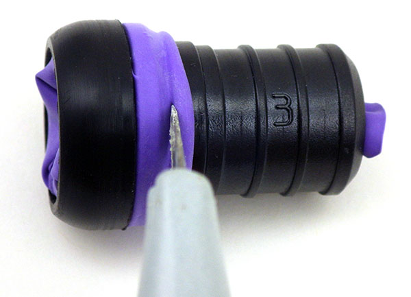
When I started building a flow sensor based on the drag/tilt principle, I knew that leaving sensors on their default factory calibration settings was not optimal, but I had so many other things to sort out regarding power use, memory handling, etc., that I left calibration to deal with later. Since I could not trust the electronic compass in the units, I simply installed the Pearls with a magnetic compass in my hand, making sure I knew which accelerometer axis was physically aligned North. But once my loggers started consistently reaching a year of operation, that “later” finally arrived. I tackled the topic of calibration with little knowledge beforehand, and there was quite a bit of background material to wade through. Rather than waffle on about it I am simply going to provide links here to some of the better references I came across:
And if that Freescale paper didn’t leave you in the dust, you could try Alec Myer’s extensive blog entries on magnetometer calibration. But since I haven’t seen a matrix operation since high school, most of that went right over my head. It didn’t help that there are so many different ways of defining a “standard” reference frame, making many code examples hard for a newbie like me to interpret. But even without the math I came away understanding that hard iron shifts the entire sensors output, while soft iron distorts it. So the goal of calibration was to transform displaced eliptical shapes into nice balanced spheres centered on the origin. And I hoped for a way to do this that would work with the many different compasses and accelerometers I had been using since I began development in 2013, because most of those flow sensors are still running.
Here I have added color to the three Plotly projections as XY (blue), XZ (orange) and YZ (green)
I had a new LM303DLHC breakout from Adafruit that I was considering because it contained both an accelerometer and a compass (having both on the same IC keeps them in alignment), so I used that to generate an initial spread of points by simply ‘waving it around” while it was tethered to one of the loggers. Then I searched for some way to display the points. I found that Plotly makes it easy to upload and visualize data-sets, and it freely rotates the 3D scatter plot via click & drag. This gave me a good overall impression of the “shape” of the data, but I did not see how this would help me quantify a hard-iron offset or spot other subtle distortions. Hidden in the Plotly settings there was a button that projected the data onto the three axis planes. Seeing that sent me back to my spreadsheet, where overlaying these three plots (and adding an circular outline to see the edges better) produced:
Projections of the magnetometer data placed on the same axes.
Now at least I could see the offsets and the other distortions well enough to compare ‘before & after’. But I still needed to figure out how to actually do a calibration. Google searches turned up plenty of code examples that simply record maximum & minimum values along each axis to determine the hard iron offset. For this “low & high limit” method you rotate the sensor in a circle along each axis a few times, and then find the center point between those two extremes. If the sensor has no offset that center point will be very near zero, but if you find a number different than zero, that number is the hard iron offset. These approaches assume that there is no significant soft iron distortion and judging from the rounded outlines in my graph, that was reasonably true for the naked LM303 board I had been waving around.
But these methods rely on you capturing the extreme values along each axis, and my data was kind of patchy. I needed to work on my Magnetometer Calibration Shuffle if I was going to capture enough points from all possible orientations. Yury Matselenak over at DIY drones offered and an alternative to my hand wavy approach using the sides of a box to calibrate the ubiquitous HMC5883L (you might want to add a leveling table). I thought that looked pretty good until I came across a technical note at the Paperless Cave Surveying site in Switzerland. In A General Calibration Algorithm for 3-Axis Compass/Clinometer Devices it states:
“A cube can be placed with any of the 6 faces up and in each case any of the 4 side faces may be in front, giving a total of 24 orientations. Unfortunately it turns out that 24 measurements are not enough for a good calibration. A perfect set of 60 orientations is contained in the symmetry group of the dodecahedron or icosahedron. However, this set of orientations is not useful in practice because it is too complex to be reproduced in the field.”
jjspierx’s rig could be built with a drill & a hack-saw.
That meant I was going to need a more advanced testing rig. I found plenty of examples on Youtube where people had fashioned fancy calibration rigs out of 3-Axis Camera Gimbals, but they looked expensive, had alot of metal in them, and I was not sure if they were robust enough to transport into the field. Then I found a post by jjspierx over at the Arduino forum, who built a yaw/pitch/roll jig out of PVC for about $20. It’s a really sweet design that could be built to just about any size. I still might make one just for the fun of it, although I think I will use nylon bolts to keep any metal away from the magnetometer.
Roger Clark’s approach posted as test_rig.jpg in the thread.
Another elegant solution was posted by Roger Clark over at the Arduino playground. His 3D printed polyhedron allowed him to put an MPU9150 into that ‘perfect set’ of orientations. “Hey” I thought to myself “That’s a Buckyball. I can make that” But as I dug intoallthedifferentwaysto make a truncatedicosohedron I had this niggling idea that somehow I might still be missing something. If this was really all it took, then why did so many people in the quad-copter & robot forums complain that they never got their compasses to work properly? The more of these complaints I found, the more I started to wonder about my sensors being too close to the Arduino, the RTC breakout, and most of all those alkaline batteries.
There was another interesting note about this at the end of that swiss paper:
“Experience shows that calibration must be repeated from time to time to avoid performance degradation due to component drift and aging. In devices using primary batteries, a calibration is needed after each battery change because the battery is unavoidably the main source of magnetic disturbance and new batteries never have exactly the same behavior as the old ones.”
The first “inHousing” test with the LM303 showing significant soft iron distortions
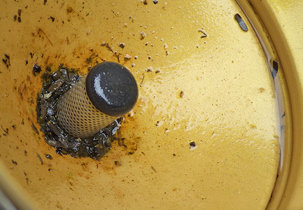
To see exactly how much of a factor this was for my loggers I mounted the LM303 sensor board in one of the underwater housings (which had a 6xAA battery pack about 10 cm from the sensor) and ran another test. The results made it pretty clear that, yes, magnetometers really do need to be calibrated inside their final operating environment. This also showed me that unless I was willing to spring for expensive degaussed batteries, I was going to need software that could provide significant soft iron compensation: the max & min only approaches just weren’t going to cut it. And I need to make sure that the battery & sensor orientations don’t not change during deployment by adding an internal brace to keep things from shifting around. It also occurred to me that there might be some temperature dependencies, but by this point I didn’t want to look under that rock and find there was even more work to do.
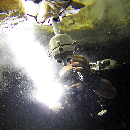
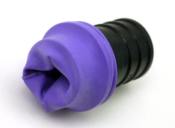
After seeing that plot I went back to the idea of building a geodesic frame big enough to contain the whole flow sensor, that could be assembled with zip-ties for transport into the field. And I think I found a way to build oneout of tubing, but in the end I simply fashioned a couple of handles that could be connected directly to the threaded ends of my underwater housing. A sliding joint on the top handle allowed me to spin the unit slowly and smoothly as I pivot my body into different positions. The whole process takes about 10 – 15 minutes, using my arms as the calibration jig. This produces a spread of points that look like the blue line plot below:
Plotly again, with lines rather than points to show the pattern in the data as I twirled the unit about its long axis. This method only rotates the unit around the Z axis, which shows up quite clearly in the data.
Although this is not the same pattern you get from a 3-axis gimbal rotation, I am reasonably confident that I have captured enough points for a decent calibration. And the handles are easily transported so that I can do some post deployment calibrations in the field on the various different housings.
Although I was still boggled by forum threads discussing the finer points of “Li’s ellipsoid algorithm”, I still had to choose some software to generate the correction factors and I wanted something flexible enough to use with any compass rather than a one-of solution that would leave me tied to a specific sensor.
The best Arduino script example of compass calibration I could find was the Comp6DOF_n0m1 Library by Noah Shibley & Michael Grant (and I will be cribbing heavily from their integer trig functions for roll, pitch & yaw…)
Using the FreeIMU GUI Toolset
A post in Adafruits support forum suggested Varasano’s FreeIMU Calibration Application. The FreeIMU calibration app was written with a GUI, but fortunately Zymotico posted a Youtube video guide that shows how a couple of simple config file edits let you run the FreeIMU GUI Toolset in manual mode: (These are screen shots from that video)
These changes allow you to run the application without the GUI, so long as you provide a couple of tab delimited text files of data. The video goes into some detail showing how to use a processing sketch to save serial output from Adafruit 10 DOF IMU as a csv file, but all I did the first few times was copy and paste data directly from the serial window into a spreadsheet, and from there into notepad. (since my units are data loggers, I could use the csv files on the SD cards for the in-housing tests I did afterwards)
Then you save “acc.txt” and magn.txt” in the FreeIMU GUI folder, right beside the freeimu_manualCal.bat file that you modified earlier. Once you have your data files in place, run “Freeimu_manualCal.bat”. On my machine the GUI still launches – displaying no data, but a command line window also opens:
Note that if you try to run the batch file that you modified with the default data files the program came with you will see NAN (not a number) errors. This is a sign that you did not save your new data files in the right directory, or that your data does not have the correct format. Once you have the FreeIMU Offsets & Scale factors in hand, the calculation is simply:
When I used this procedure on the battery distorted data from that first housing trial the before and after plots looked like this:
Now that’s what I wanted to see! Even better: FreeIMU generated corrections for both the accelerometer and the magnetometer at the same time. (Units are lost when normalizing the ellipsoid because of the scaling factor. You can get acceleration back by multiplying by 9.80665 m/s*s.)
Unfortunately FreeIMU also comes with a whopping 300MB folder of support files, and with Fabio Varesano’s passing there is a real question about whether his software will continue to be available (or how long it will be updated to prevent some python version dependency problem from cropping up). I have also run across some scary looking hacked pages in the old varesano.net site, so it might be safer to use the wayback machine to search through it.
Using Magneto v1.2
My search for alternatives to FreeIMU lead me to Magneto v1.2 over at the Sailboat Instruments blog That software was recommended by some heavy-hitters at the Sparkfun and the Arduino Playground forums, with one helpful person posting a step by step guide to Calibrating the LM303 with the Magneto software. With my earlier tests, I already had raw magnetometer data in text file, but I did not get good results until I noticed that before Scirus launched Magneto he was preprocessing the raw magnetometer readings with an axes-specific gain correction(See Table 75: Gain Setting on datasheet) to convert the raw output into nano Tesla:
Xm_nanoTesla = rawCompass.m.x*(100000.0/1100.0); // Gain X [LSB/Gauss] for selected input field range (1.3 in these case) Ym_nanoTesla = rawCompass.m.y*(100000.0/1100.0); Zm_nanoTesla = rawCompass.m.z*(100000.0/980.0);
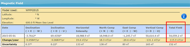
Save this converted data into the Mag_raw.txt file that you open with the Magneto program. Then your numbers match the magnetic field norm (or Total intensity) values that you get from the NOAA or BGS sites:
To use his method with a different magnetometer, you would have to dig into the datasheets, and replace the (100000.0/1100.0) scaling factors with values that convert your specific sensors output into nanoTesla. On the LM303, that factor is different on the Z axis than it is on the X & Y axes. But according to the author on the Sailboat Instruments site you only need to match the total field “norm” values if you want the final output on an absolute scale:
“Magneto expects to receive raw data in +- format (a value of zero indicating a null field in the current axis), but not necessarily normalized to +-1.0.
If your sensors have SPI or I2C outputs, they will usually directly produce the required format. For example, the MicroMag3 magnetometer directly produces counts from -3411 to +3411, and the the SCA3000 accelerometer directly produces counts from -1333 to 1333, and Magneto can process directly these values, without the need to normalize them to +- 1.0. I understand that a normalization may be desirable to avoid machine precision problems, but this has not been the case with these sensors.
If your sensors produce voltage levels that you have to convert to counts with an ADC, you have indeed to subtract a zero field value from the ADC output before using Magneto. You would then normally choose the maximum positive value as input to the ‘Norm of Magnetic or Gravitational field’.
But this norm value is not critical if all you want to calculate later on is a heading (if it is a magnetometer) or a tilt angle (if it is an accelerometer). You can input any reasonable value for the norm, the correction matrix will be different by just a scaling factor, but the calculated heading (or tilt angle) will be the same, as it depends only on the relative value of the field components. The bias values will be unchanged, as they do not depend on the norm.”
Once I had my raw readings at the same scale as the Total Intensity numbers, I could hit the calibrate button, taking care to put the generated correction factors in the right section of the matrix calculation code:
Rather than simply finding an offset and scale factor for each axis, Magneto creates twelve different calibration values that correct for a whole set of errors: bias, hard iron, scale factor, soft iron and misalignment. As you can see from the example above, this makes calculating the corrected data a bit more involved than with FreeIMU. I am not really sure I want to sandbag my loggers with all that floating point math (mistakes there have given me grief in the past) so I will probably offload these calculations to post processing with Excel. To check that your calculations are working OK, keep in mind that in the absence of any strong local magnetic fields, the maximum readings should reflect the magnetic field of the earth which ranges between 20 and 60 micro-Teslas.
When I ran Magneto on the same data set I tested with FreeIMU, the x/y plots were once again transformed into perfect spheres, centered on the origin. Since I could not determine which software had done a better job by looking at the graphs, I took a hint from the Scirus post and decided to run the post-calibration numbers from each application as input to both programs. Since the FreeIMU “normalized” to unitless +-1 values, I had to multiply it’s output by my local 54,000 nT total field to use it’s post calibration output in Magneto. As you might expect, each program thought it’s own output file was perfect, requiring no further offsets, etc. But Magneto thought there were still “slight” offsets in the corrected data from FreeIMU, while FreeIMU thought the output from Magneto’s corrections were fine. I have slight in quotes there, because Magneto’s suggested bias corrections to the post FreeIMU data amounted to less than 0.1% of the total range. Given all the real world factors that affect compass readings, I’d say the two calibrations are functionally equivalent, although I suspect Magneto can deal with more complicated soft iron distortions.
What about the Accelerometers?
A side benefit of all this is that both programs can be used to calibrate accelerometers as well! FreeIMU does this right from the start, producing unit-less +-1 results. For Magneto you might again need to pre-process your specific raw accelerometer output, taking into account the bit depth and G sensitivity, to convert the data into milliGalileo. Then enter a value of 1000 milliGalileo as the “norm” for the gravitational field. (Note: With the LM303 at the 2G default settings, the sensitivity is 1mg/LSB, so no pre-processing is needed. However the 16-bit acceleration data registers actually contain a left-aligned 12-bit number with extra zeros added to the right hand side as spacers, so values should be shifted right by 4 bits – which shows up as dividing by 16 in the Scirus example)
Now that I finally have a way to calibrate my sensors, I can move on to calculating the vectors for my flow meters. Being able to derive the sensors an instantaneous yaw angle from the magnetometer data would means that I no longer need to worry about the physical orientation of the sensors to calculate windroseplots with circular averages. Of course bearing calculation brings me right back into the thick of the Quaternion vs Euler Angledebate, and I have more homework to do before I come to grips with any of that. But I also have so much soldering to do…perhaps I’ll deal with it “later” 🙂
Addendum 2017-04-20:
A pingback put me onto a long discussion at Pololu of someone working their way through tilt compensation on an LM303. They mention the use of MagCal, another software option which confusingly, outputs the INVERSE of the matrix that you get from Magneto. But there are tools to flip the matrix if that is the software you have available.
Addendum 2017-10-12:
Accelerometers are so jittery, that it’s always a good idea to read them a few times and average the results. Paul Badger’s DigitalSmooth does an excellent job when you feed it 7-9 readings for each axis. This filter inputs into a rolling array, replacing the oldest data with the latest reading. The array is then sorted from low to high. Then the highest and lowest %15 of samples are thrown out. The remaining data is averaged and the result is returned, allowing you to calculate things like tilt angle.
Addendum 2018-04-11:
Posting a quote here from jremington, as several people have emailed questions about IMU’s, which add a gyro into the mix.
“The accelerometer is used to define pitch and roll (while the craft is not accelerating or rotating), while yaw is defined by the magnetometer. Another way to look at this is that the magnetometer defines the North direction, while the accelerometer defines the Down direction. North and Down are combined to generate East, for a full 3D coordinate system called North East Down (NED). Both of these sensors are required to determine absolute orientation. The gyro only measures rotation rates and cannot be used to define any angles. It simply helps to correct for the fact that the acceleration vector is not g (Down) if the craft is rotating or accelerating.”
Again the place to start reading about IMU’s is probably the CHrobotics library. And I’ve heard rumors that the MPU6050 with the i2cdevlib DMP example sketch generates both quaternions and sensor-fused motion data at ~100Hz, so that might be a good code reference…
Addendum 2023-12-01: A quick testing platform for your sensors
People are not likely to jump into building underwater units immediately, so you’ll need a platform to test the different accelerometers on the market. Our 2-Module Classroom data logger is probably the fastest way to get a testing fleet together, with mini breadboards making the sensor swaps effortless. Even relative power hogs like the ADXL345 should be OK for a few weeks of operation with the 1000µF rail buffer.
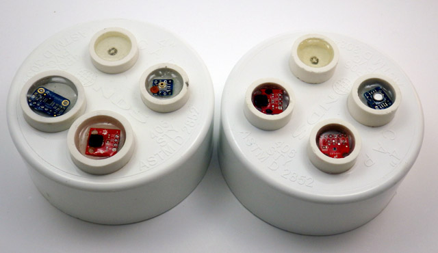
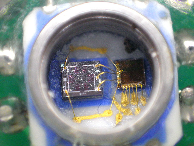
As I gear up for the next round of fieldwork, I thought I would introduce the newest addition to the Cave Pearl lineup: A logger for Pressure, Relative Humidity, and Temperature
Left: MCP9808, HTDU21D, MS5805-02 [rgb LED on both] Right: HTDU21D, TMP102, MS5803-02
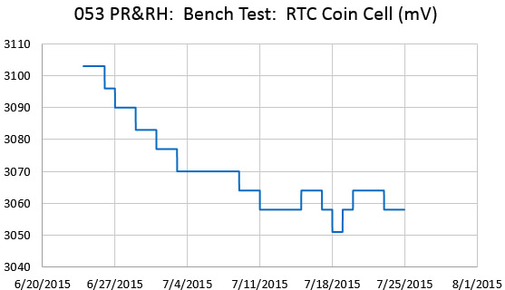
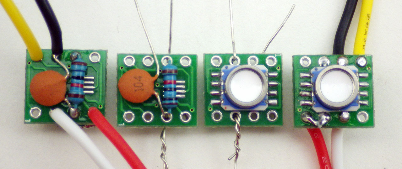
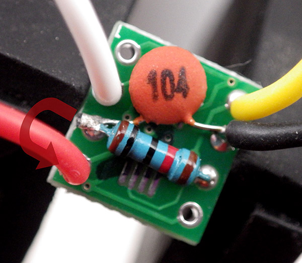
When one of the drip sensors from the last deployment failed early, I went hunting for information to see if I could corroborate the dramatic increase in drip rate it recorded before it expired.
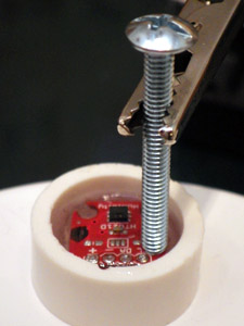
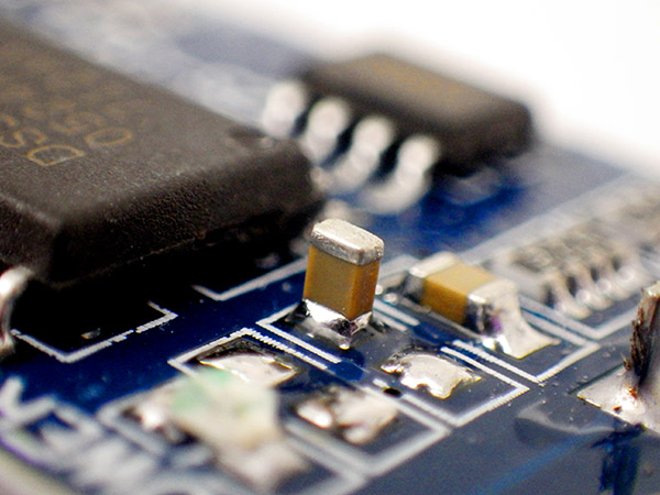
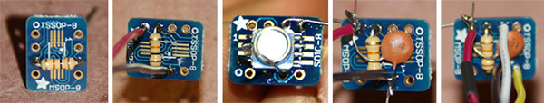
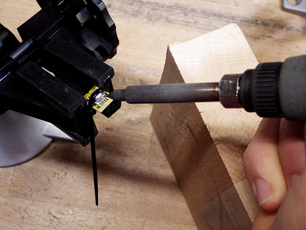
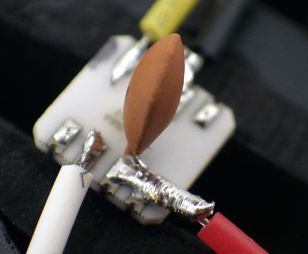
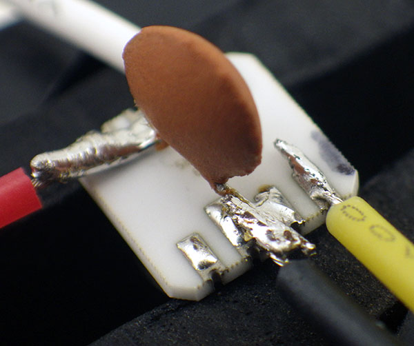
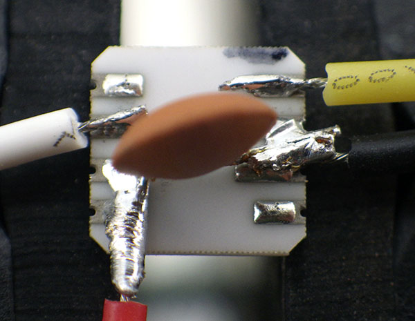
The pass-through wires push the breakout boards into odd angles, so I tack them down with a pea-sized bead of JB Plastic Weld while applying some top pressure to hold the board level. (takes ~15 minutes) Then I test the sensors “dry”, while they can still be removed. Potting in epoxy is the last step.
This made it clear that there really was not alot of good climate station data near our deployment site, and that even if that data was available, it still was not going to tell us much about the conditions down below. So I spent a couple of days cobbling together these mini “in-cave” sensor stations. I will try adding an anemometer to them them later, if I can find one that draws a low enough current to operate within my power budget.
These first units which will be co-deployed so that we can compare the performance of the different sensors. One uses the MS5803-02 sensor (already proven robust enough for five months at 5m in 50% marine water), and the other is using the much more affordable MS5805-02 which is only listed as ‘splash-proof”. This comparison is test was almost effortless to do, as both sensors are code compatible, with the exception of the CRC check.
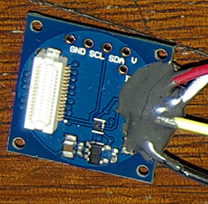
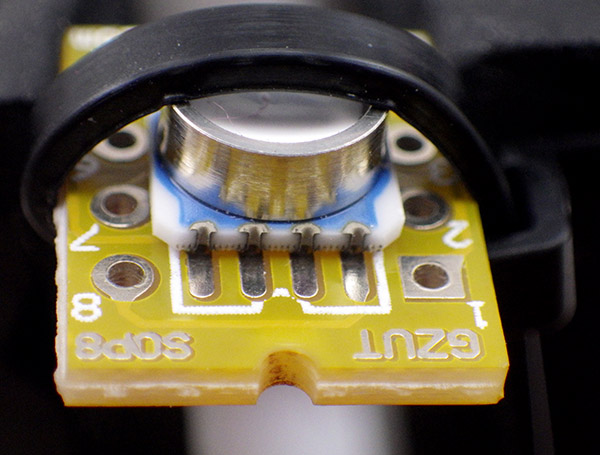
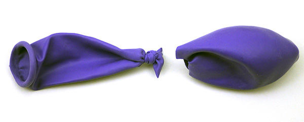
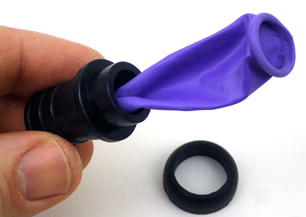
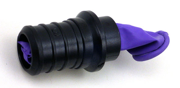
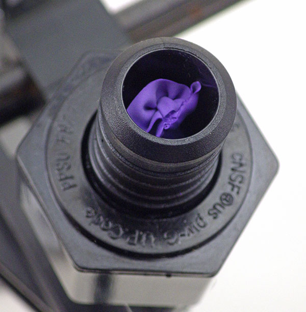
The cap fits because the HTU21D from Measurement Specialties has a similar form factor to the Sensirion SHT series humidity sensors. But you need to cut the legs off the cap to flush mount on the Sparkfun board as I have here.
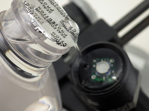
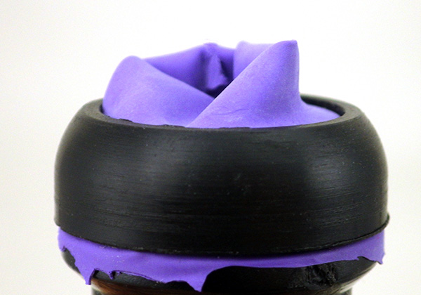
For Relative humidity I am using the SparkfunHTU21D with the Sensirion SF2 protective cap. The trick to installing these caps on the sparkfun board is to first bond the cap to the board with a tiny amount of epoxy applied all the way around the base of the protective cap with a toothpick. Once the cap is bonded to the board you can cover the rest of the topside of the breakout with epoxy, taking care not to let it run up to the protective fabric, where it could wick in and seal off the sensor. Hopefully this waterproof cap will protect the sensors well enough, but I am not expecting miracles because most RH sensors go a bit squirrly in caves, where the environment can be at 100% RH for a good deal of the time. I was very happy to discover that this sensor auto-sleeps after each reading, so it adds almost nothing to the power budget. The units are going into the field in a few days, so I will have to look at something likesaltcalibration of these humidity sensors later.
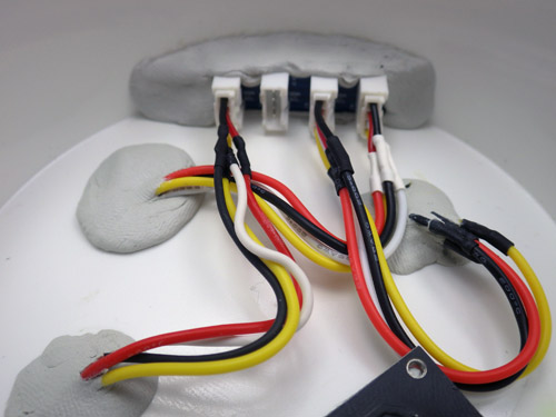
JB Plastic weld putty lets me tuck a trimmed Groove I2C hub up out of the way, so only one I2C jumper runs from the cap to the logger platform, taming the spaghetti monster.
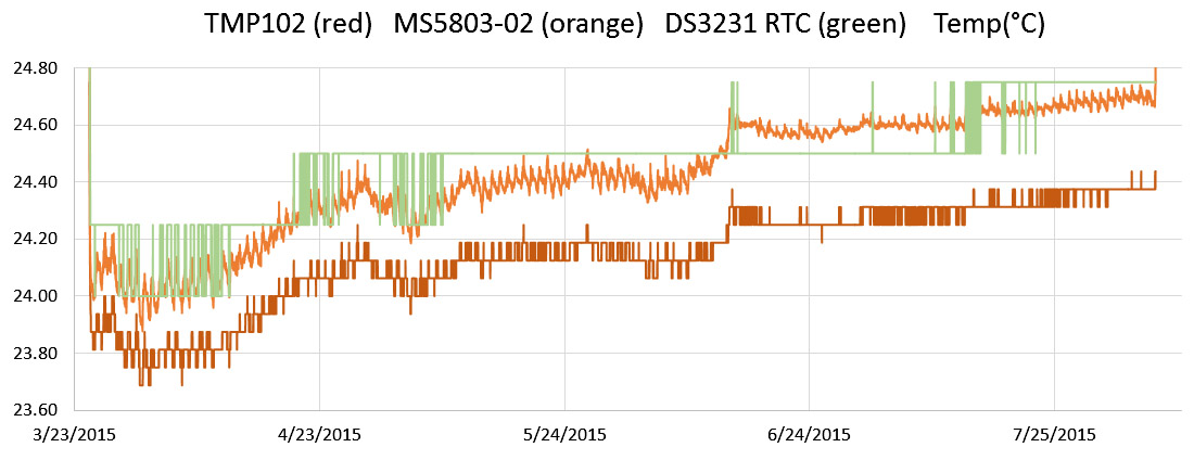
For the hat-trick I am trying out two different I2C temperature sensors. Technically speaking, the pressure and RH sensors already collect temperature data, which they need for their internal calibration, but I just thought that it would be nice to do a little experiment comparing Sparkfuns TMP102 to Adafruits MCP9808. While their precision is identical (0.0625 C), the 9808 claims much better accuracy.
I already had the TMP102’s working in one-shot mode, but even Adafruits generally good code support did not cover putting the MCP9808 into its low current shut-down mode, and this is critical for my application. A little browse through the datasheet, and it turned out to be pretty easy to do, and I thought I would post this for others wanting to use the MCP9808 for logging:
Wire.requestFrom(MCP9808_I2CADDR,2);
bytebuffer1 = Wire.read(); //upper bits first 15-8
bytebuffer2 = Wire.read(); //then bits 7-0//set “bit 8” to “1” to enter shut down mode
bytebuffer1 |= (1 << 0);
//x |= (1 << n); // forces nth bit of x to be 1. all other bits left alone
Wire.beginTransmission(MCP9808_I2CADDR);
Wire.write((uint8_t)MCP9808_REG_CONFIG); //register pointer
Wire.write(bytebuffer1); //
Wire.write(bytebuffer2); //this one is unchanged probably could skip it
Wire.endTransmission();
}
//
void MCPwakeup() {
Wire.beginTransmission(MCP9808_I2CADDR);
Wire.write((uint8_t)MCP9808_REG_CONFIG);
Wire.endTransmission();
Wire.requestFrom(MCP9808_I2CADDR,2);
bytebuffer1 = Wire.read(); //upper MSB bits 16-8
bytebuffer2 = Wire.read(); //then LSB bits 7-0//set bit 8 to 0 = Continuous conversion (power-up default)
// x &= ~(1 << n); // forces nth bit of x to be 0. all other bits left alone.
bytebuffer1 &= ~(1 << 0);
Wire.beginTransmission(MCP9808_I2CADDR);
Wire.write((uint8_t)MCP9808_REG_CONFIG); //register pointer
Wire.write(bytebuffer1);
Wire.write(bytebuffer2); //this one is unchanged probably could skip it
Wire.endTransmission();
}
Except for the bit-math, I use the same method here to wake up and shut down the sensor, but since the default values of the config register are all zeros, you could also use the much simpler:
to reset all defaults & launch continuous measurement mode. I think the soft reset does the same thing, but I have found that some sensors make you wait much longer after a “soft reset” before they give you good data than they do if you use a sleep/wake method. When possible I let my sensors go through a couple of conversion cycles to flush old data out of the registers before I read them.
I have also learned some hard lessons about not trying to do calculations on a limited platform like the Arduino if I can avoid it. So all the sensor data is being saved as raw output in the log files. I always get better results when I do the conversions later with a spreadsheet.
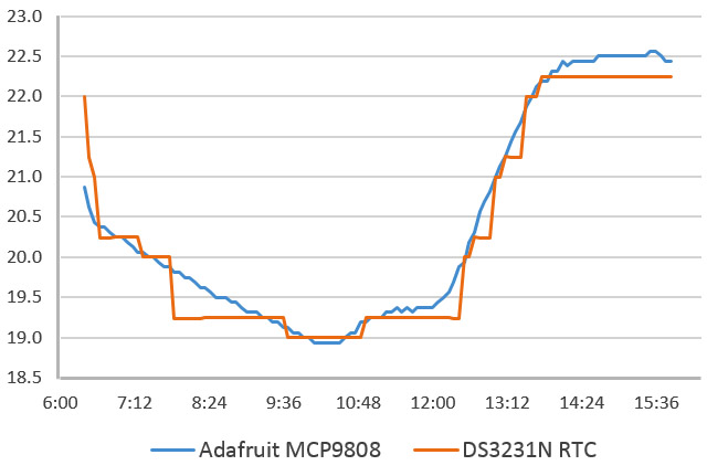
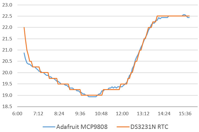
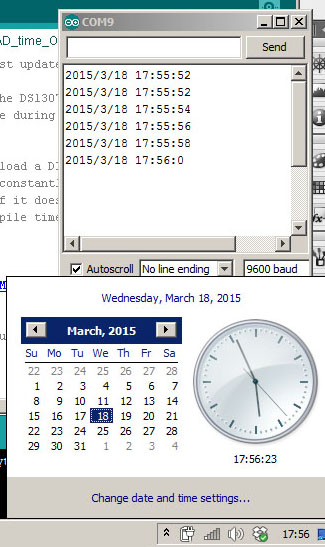
…And just to go completely over the top, I also record the temperature register of the DS3231 RTC. While this is certainly the least capable sensor in the mix, I am curious how it tracks against the others, in terms of accuracy.
Addendum 2015-02-27
As I put the first units into the field a couple of days after they were built, I did not have a chance to really play with them. So I recently built a couple more, using the TMP102 for temperature, MS5805-02 pressure sensors. One was built with the Sparkfun HTU21D breakout, while the other used a $5 noname HTU board from eBay. In my tests so far, both deliver identical humidity readings, and both of these mini ultra based loggers sleep at 0.08 mA, which bodes well for these guys making it to my year of operation benchmark.
Addendum 2015-06-22
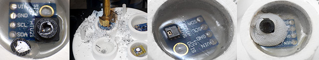
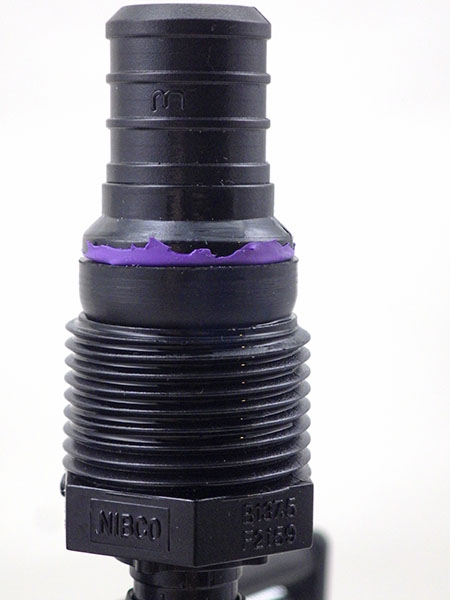
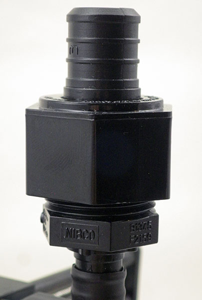
After building a few more of these I ran into a problem with epoxy wicking into the RH sensors before it cured. This is impossible to see under that SF2 protective cap so the only option is to drill out the bad sensor the next day. To prevent this from happening again, I now pot the RH sensor without the caps, and then tack the cap down with plumbers putty after the epoxy is dry:
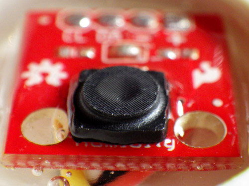
Despite the ease with which I got the DS18B20 one wire temperature sensor running, I would prefer to use all I2C sensors for a modular system that lets me swap the data logging platform and the sensor housings in the field. The Texas Instruments TMP102 is very low power 12 bit sensor capable of reading temperatures to a resolution of 0.0625 °C and Sparkfun sells them on a breakout board for only six bucks.
There are plenty of basic starter scripts out there that just read the temperature register, and leave the units running at the default settings. However for my long term deployments I really wanted to make use of the “one-shot” mode that this sensor supports, where the unit auto-sleeps by default until you ask it to make another reading. While this doesn’t save that much power (it brings the sensors quiescent current from 10μA down to 1μA) I figured it could also reduce the noise on the I2C lines, and the BMA180 accelerometer that shares those lines is sensitive to absolutely everything.
For those who just want a library for this sensor, there is one here and here , but I wanted a more transparent approach, because sooner or later, I will need to integrate all my individual sensor scripts into the next Cave Pearl codebuild. If I hide my functions in a library, it will be that much harder to see where duplication might be eliminated.
Because this sensor stores data in 16 bit registers (outlined here, but their code is somewhat confusing) , you have to do some juggling to reconstitute the data after reading out two register bytes. This gets a little complicated if you reach temperatures below zero because the negative numbers are represented in binary twos complement format. Fortunately that is not an issue in caves, and the twos complement stuff does not need to be done on positive numbers. You also don’t need to get into the 13bit “extended” mode of this sensor unless you are measuring temperatures beyond the normal –25°C to +85°C range.
You can download my TMP102 script HERE, This code produces the following output:
Initializing TMP102 Temperature sensor…
Integer data before conversion: 458
Temperature in deg C = 28.6250
Success:TMP102 has been initialized
Integer data before conversion: 457
Temperature in deg C = 28.5625
Integer data before conversion: 458
Temperature in deg C = 28.6250
Integer data before conversion: 480
Temperature in deg C = 30.0000
Integer data before conversion: 485
Temperature in deg C = 30.3125
Integer data before conversion: 489
Temperature in deg C = 30.5625
Integer data before conversion: 492
Temperature in deg C = 30.7500
….
(Note: I had my finger on the sensor here, to show the readings changing…)
The readings stabilize pretty quickly on the desktop, which is always good to see with a new sensor. Now that I have it running, I will build a special test unit with the TMP102, the DS18B20 (identical to TMP102 specs: 0.0625 °C/lsb & ± 0.5°C), and one of the MS5803 pressure sensors installed (16 bit resolution of 0.01°C but poor accuracy ± 2.5°C). That should let me assess issues like offsets, drift and noise as I select the best temperature sensor to adopt. I will have the 102 potted in JB weld on the outside of the housings, so I suspect there will be some thermal lag to deal with as well. (I wonder if I could use some kind of heat pipe there?)
Addendum 2014-06-17:
If I have issues with the TMP102, I may try to get a hold of a TMP112 which is code compatible, and has a slope specification that can be calibrated for better accuracy.
Addendum 2014-12-08:
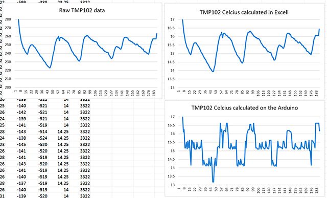
I will post more detail on this later, but since I just ran across this problem, and I thought I should post to let other people know about it: For a long time I though my TMP102’s had a weird spiky noise problem which I tried to hammer out with sample averaging, but it was not the sensor, it was the floating point calculations on the Arduino. The two graphs on the right were derived from the raw sensor data with exactly the same equation:
It’s possible that I caused this problem by forgetting to use proper casting in the calculations.
ie: TEMP_degC =TEMP_Raw*0.0625 vs TEMP_degC =(float)TEMP_Raw*0.0625
but just in case, I am going to avoid float calculations on the Arduino. You can always save your “raw” sensor data for processing later.
Plenty of these old geeetech breakouts selling on eBay. I know I am supposed to decouple VDD and VIO, but I have not figured out how to do that yet.
Up to this point I have been measuring displacement with the Bosch BMA250 on the Tiny-Circuits accelerometer board. But that sensor has a minimum range of 2g, using less than half of its 10 bit ADC in my tilt sensing application. Given that just about every electronic widget these days seems to rely on haptic feedback, I thought there would be a selection of other sensors out there to choose from in the 1 g range, so I was quite surprised to find out that there are only a couple of low g sensors on the market, and only the Bosch BMA180 uses an I2C interface. I was already using the 250, and that was pretty easy to get rolling, so I thought that it was going to be a piece of cake to switch over….
But the BMA180 is the gnarliest sensor I have worked on to date, with a spaghetti monster of co-dependent register settings, and an obtuse snarbuckle of a data sheet. But a 14bit ADC at 1g would almost triple the sensitivity of the Cave Pearls (In theory, registering a 0.25º tilt change), and for that I was willing to spend a week learning a bit about shift notation and masking to use this incredibly twitchy bit of kit. And reading data out of the registers is not even the biggest challenge: trade-offs between sensitivity and spiky random noise rapidly gets you into a tangle of offsets, sampling frequencies and filtering modes that don’t get explained at all well in the documentation.
I started out with general accelerometer references by Texas Instruments, and Freescale, which tend to focus on the calculations required to turn generic accelerometer readings into roll, pitch and yaw. From there I found a few BMA180 link pages, but most of the sites were for dedicatedquadcopter IMU’s like the multiwii, which generally combine data from an accelerometer with that from a gyroscope, using complementaryfilters or more complicated Kalaman filter calculations. Most of these approaches are aimed at real time smoothing of continuous data streams, while I am interested in infrequent, high accuracy readings. There were a fewseismometer projects, which showed me how to set the range, frequency & bandwidth filters, but they usually focus on getting interrupt alarm modes working, which is not useful for my application. Some mentioned calibration in passing, but there still was not much signal to noise optimization being done, and after several days I still could not find a single example of someone putting the sensor to sleep between readings to save power.
Once you start sending the readings to the serial monitor, you see how jumpy this sensor is just sitting on the desk, in low noise mode, with the lowest availiable bandwidth filter (10Hz). I tried a moving average with the arduino library, and then using a basic smoothing routine, but the readings were still pretty unstable. I finally managed to tame the gremlins with the digital smoothing method from Paul Badger, which throws away the high and low values from a set of readings, before averaging the rest of the data. The trade off here is that while this sensor only draws 1025µA in low noise mode, I have the whole system running for 1 second to capture enough readings for this process.
Note: the sensor was not level here, just hanging on some wires, so the x & y axes are not zero.
Given how tough it was to get this far, and how few people are using this accelerometer as a stand alone device, I though I would post the rough BMA180 accelerometer script which now produces reasonably stable 14 bit readings. The code has a nice function for dealing with individual register bits with a mask, which I am sure will come in handy for other sensors. I still don’t grok hex numbers, so I have written the masks as long form binary so I can see exactly which bits are being modified.
As I am using the BMA180’s default low-noise mode, I am simply relying on the factory calibration in the sensors ADC. But occasionally one of the readings will spike over 16384, so I know I still need to implement further offset calibration. I have already tried a few simple“high/low”methods, but most of them have actually made the x & y offsets worse (perhaps I need to use a jig for calibration?) and it will be a while before I can tackle least squares or gauss newton . To be honest, I am not even sure if its worth trying to attempt the 3D ellipsoid corrections on the Arduino’s cpu. (and I don’t know if my “organic” processor is up to the task either 🙂 )
Addendum 2014-11-04
I finally figured out how to get the BMA180 sensor sleeping to save power between readings:
// first check if the sensor is in sleep mode by looking at the content of bit1 in CTRL_reg0 // if so wake up the sensor by setting the sleep bit (bit1 of reg0) to “0” // you do not need to set the ee_w bit before doing this! // but the dis_wake_up bit must be “1” to disable the auto-sleeping function first // (I do this in the initialization)
bytebuffer1 = i2c_readRegByte(BMA180_ADDRESS, BMA180_CMD_CTRL_REG0);
bytebuffer2=bytebuffer1;
bytebuffer1 &= B00000010; //knock out the other bits
if(bytebuffer1){ // if “true” then the bit was “1”
bytebuffer2 &=~ (1<<1); // forces 1st bit of bytebuffer2 to be 0. all other bits left alone
bytebuffer1 = i2c_writeRegByte(BMA180_ADDRESS, BMA180_CMD_CTRL_REG0, bytebuffer2);
delay(10);// now give the sensor some time to wake up
}
… now take your readings….
and then to put it to sleep again:
// put the BMA180 sensor to sleep again by setting the sleep = bit 1 of reg0, to “1”
bytebuffer1 = i2c_readRegByte(BMA180_ADDRESS, BMA180_CMD_CTRL_REG0);
bytebuffer1 |= (1<<1); // forces first bit of bytebuffer1 to be 1. all other bits left alone.
bytebuffer2 = i2c_writeRegByte(BMA180_ADDRESS, BMA180_CMD_CTRL_REG0, bytebuffer1);
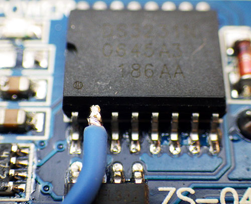
Connecting to Vcc and GND further along the cable is easier than putting little jumpers on the surface of the board.
Because the sensor now sleeps below 1uA, I can let it run in its power hungry (~1mA) low noise mode when I need to take a reading, without having to worry about other power saving from things like the oddly named “wakeup” modes. The bitmath is from CosineKitty’s tutorial at the playground which showed me how to toggle just that one single bit in the register.
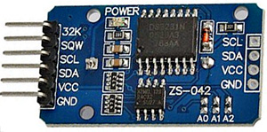
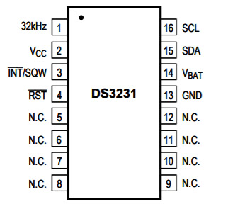
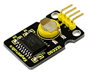
A ±2ppm DS3231N for less than $1? The industrial SN variant is rated for a wider -40°C to +85°C temp range than the N. The ±5ppm-Mvariant hasdramatically different noise/drift characteristics..
Since the Cave Pearl is adata logger, it spends most of the time sleeping to conserve power. So you could say that the most important sensor on the unit is the real-time clock (RTC), who’s alarm signal wakes the sleeping processor and begins the cascade of sensor readings. I built the first few beta units with the DS3231 Chronodot from Macetech (about $18 each), but I kept on stumbling across cheap RTC modules on eBay, Amazon, etc. and I eventually bought a couple to try them out. While I waited for them to ship on the proverbial slow boat, I did some digging, because these modules were (almost) selling for less than the chip itself if I bought them directly from trusted sources like Digikey, Mouser, etc.
So perhaps they are counterfeitchips, which are simply pin & code compatible? I also found rumors about “ghost” shifts, where legitimate manufacturer plants/equipment are used off the clock to produce extra parts. Or legitimate production runs which test out defective (if 10% of a run’s chips are bad, they often scrap the entire run) but someone intercepts the chips before they can be destroyed, and they resurface on the grey market. But even with all these possibilities in mind, I still have to make the Pearls as inexpensive as possible if they are going to be deployed in large numbers, and having an I2C eeprom on the board for the same money, made the temptation too great to resist.
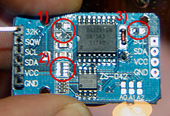
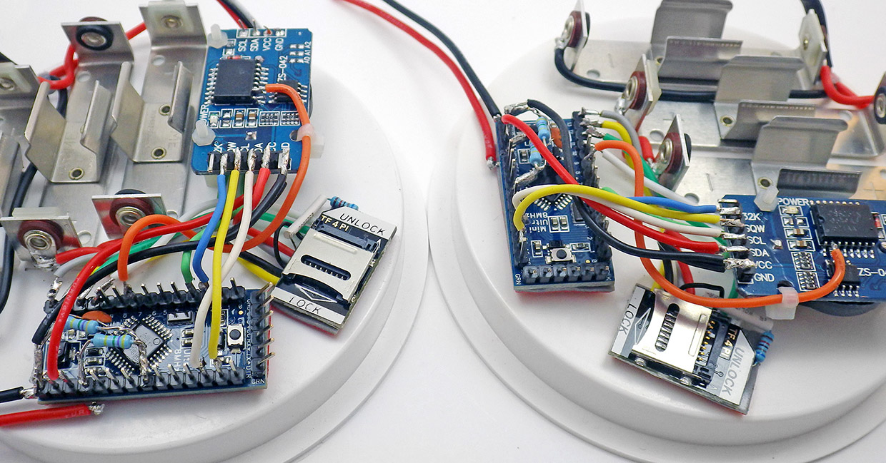
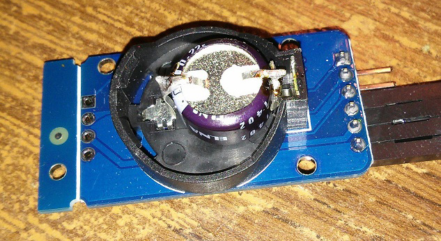
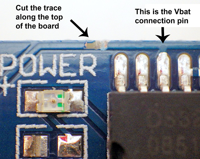
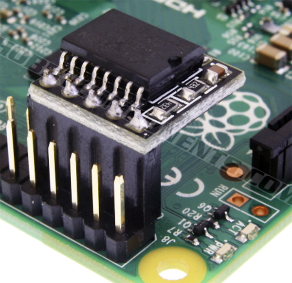
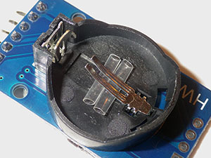
When the RTC’s arrived they had an LIR2032 rechargeable battery underneath the board, and a LED power indicator above. I had a feeling that neither of these were going to be friendly to my power budget so I went hunting for the schematics to see what I could do to improve the situation. I quickly found an Instructables post which described how to remove the battery charging circuit from a very similar DS1307 module, and then I found the datasheets and schematic for this DS3231 module over at at a site in Europe. Most of the parts were pretty straight forward:
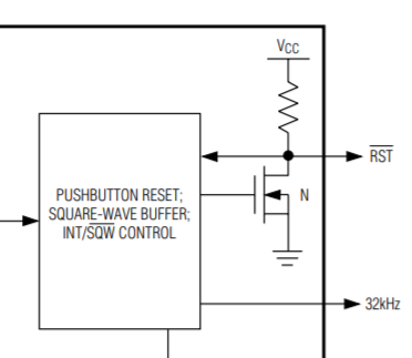
But thanks to the tutorial by msuzuki777, I immediately zeroed in on a few parts on that circuit diagram that could be removed:
The power indicator (1) was pretty pointless, so that was the first thing to go. I already had pullups on the I2C lines, so they were not needed here, but they were in a combined 4 resistor block, which meant that to get rid of the pullups on SCL and SDA, I also had to remove the pullup on the alarm line. This had me a little concerned, as that alarm line is vital to the whole design. Without that resistor on SQW, I am relying on the weak internal processor pullups keep the alarm line high with:
digitalWrite(INTERRUPT_PIN, HIGH); //pull up the interrupt pin
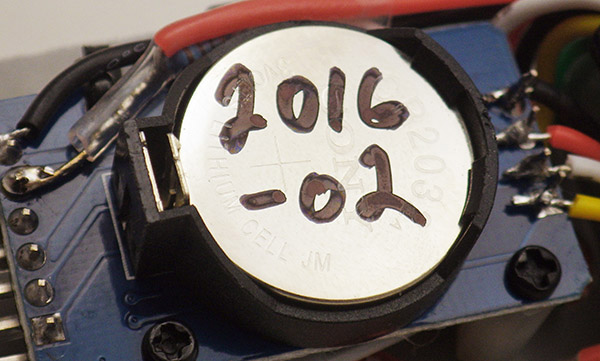
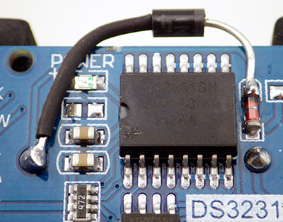
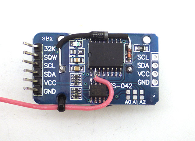
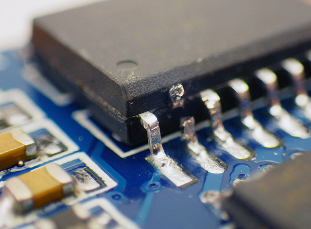
Then I looked at the 200Ω resistor & 1N4148 diode (3) that are supposed to provide a trickle charge to the rechargeable battery, though the folks at BU suggest this is a bad idea. The LiR2032 that these modules ship with is 3.6v, and while capacity varies depending on where you buy them, most provide 35mah to 45mah capacity. Looking at the power draw from the DS3231, a fully charged battery would keep the unit backed up for at least 200 days(in a perfect world, with no self discharge, etc) But, it requires a 4.2v charging voltage for maximum charge, so vcc would have to be above 4.3-ish volts. I don’t anticipate my 3x AA power supply staying in that territory for the duration of a long deployment (especially if I end up powering the units from cheap AA’s) so there really was no compelling reason to keep the charging system in place. Once I de-soldered the resistor, I popped in a CR2032 (3v 240mAh) as a replacement which should backup the clock for several years of operation.
Then we come to the AT24C32N(2.7 to 5.5v)memory chip that is also on this breakout board. Another of those 4 resistor bricks is lifting pins 1,2 and 3 to Vcc, so according to the eeprom datasheet this unit is being set to 0×57 on the I2C bus. There are pads there to ground out these lines if you need to reassign the address to something else. Although I have already determined that eeprom is not the power savior I hoped it might be(all that eeprom reading & writing uses about 1/3 the power of simply writing the data to the SD card in the first place) it’s presence lets me be really lazy on the coding and just pop any numbers or characters that I want into a PSTRING’d buffer which then gets sent to a standard eeprom page writing routine. This flexibility allows me to swap sensors with dramatically different output, while retaining essentially the same code to handle the eeprom loading and the transfer of data back out to the SD card. If you want more information about that you can head over my earlier post on buffering sensor data to an I2C eeprom for the gory details.
The May 2014 build of the data logging platform, which used a hacked Tinyduino light sensor board to regulate & pull up the I2C bus. SQW is soldered to interrupt pin 2. Later in 2014 I switched to Pro Mini style boards with 3.3 v regulators, so I left that four resistor block in place ( 2 in the schematic above) to provide I2C and SQW pullup.
To top it all off, the cascade ports on the far side of the module let me “just barely” fit the rtc, the I2C hub(with corners sanded off), and main TinyDuino stack onto the platform in the middle of my housing. I am lifting the voltage regulated I2C bus traces from the TinyDuino light sensor board, so I am also hunting around for an off the shelf vreg & level shifter combination to replace that hack (because that bit of soldering is a pita). But overall, I am very happy with this build, as all the central data logging functions have come together into a nice securely mounted package, that should withstand significant knocking about during the deployment dives. Of course there is plenty of field work testing still to be done, so time will tell (sorry, couldn’t resist…) if these cheap RTC’s will cause more trouble than they are worth.
Addendum: 2014-05-21 It just occurred to me that sooner or later Tinycircuits will be releasing an RTC board, and that will give me a chance to directly compare these cheap boards to a “trusted” clock signal provided that their chip does not want the same bus address. Or if their clock wants the same I2C bus address as this eBay RTC, I could use a DS3234 on the SPI bus. I will post an update when I can run that test to spot clock drift, alarm errors, etc. Several sites have mentioned that real DS3231’s drift about 2 seconds per month, while the cheaper ds1307’s drift 7-10 seconds per day. If you have the right equipment, you can make the chip even more accurate by adjusting the aging offset register.
Addendum: 2014-05-21 I just realized something else odd about my setup here. The I2c bus is held at 3.3 volts by the regulator on the tiny light sensor shield, but I am pulling up the SQW via the tinyduino cpu, which is following the voltage on the battery pack because the tiny CPU is unregulated. So the pull-up voltage on the alarm line is out of sync with the voltage seen by the rest of the DS3231 chip….hmmmm. (2014-10-28 : data sheet says its Ok to pull the line all the way up to 5v, even on Vbatt)
Addendum: 2014-07-01 I created a very inexpensive 3-component data logger with this RTC, a Pro Mini mcu board, and a cheap sd card adapter. And you can see a post about the latest version of that logger concept here which has added a power shutdown feature. In those Pro Mini based loggers I do not remove the I2C pullup resistor bank as shown earlier in this post (2 in the photo above), as the removal is only needed if you already have pullups in place, as I did when using the hacked Tinyduino light sensor board to drive the RTC. I have built many loggers now, and some of them have come close to 400,000 alarms & eeprom write cycles, so these cheap RTCs are proving to be pretty durable.
Addendum: 2014-10-28 Pin Powering the RTC
Wedge a tweezer tip behind the pin and “gently” lever it away from the board as you apply an iron to the pad. Then solder your pin-power jumper directly onto that raised leg. At this point the chip’s Vcc pin is no longer connected to the Vcc line on the breakout board, so you can leave power on the board’s Vcc line to pullup SDA,SCL,SQW and supply power to any I2C devices / sensors you have connected to the cascade port.
I have noticed that when I power this module from Vcc at 3.3v, it draws around 89 µA. But according to the datasheet,the RTC should only draw ~2 µA on average when powered from Vbat. (1µA baseline plus about 500µA for 100ms every 64 seconds when the crystal is doing temperature compensation) Nick Gammon found an elegant way to power a DS1307 by connecting Vcc to one of the Arduino pins , driven high in output mode when the system is active. (look about half way down the page) When the Arduino pin is low, the clock reverts to battery power, and goes into the low current timekeeping mode. But according to the datasheet, Bit 6 (Battery-Backed Square-Wave Enable) of control register 0Eh, can be set to 1 to force the wake-up alarms to occur when running the RTC from the back up battery alone. [note: This bit is disabled (logic 0) when power is first applied] So you can still use the RTC to wake the Arduino, even if you have de-powered it by bringing the pin low. I have tested this and it seems to work fine on my RTC modules, reducing the sleep current by about 70 µA. (or ~ 600 mAh per year = almost 1/4 of a AA) Tests are underway now to see if this is stable as a direct jumper to the pin without using a current limiter, which might give me a problem with inrush current unless I also add a resistor as N.G. did. Also keep in mind that this only works because the RTC was designed with backup power circuitry. In general, de-powering I2C Slaves is not a good idea because the pullup resistors keep the SDA and SCL lines high. When a regular I2C sensor has no power, you could leak current via SDA and SCL through the I2C device to GND.
And since my loggers are going in caves where the temperature does not change very quickly, I am bumping the temp conversion time from 64 to 512 seconds as per Application note 3644, in theory reducing the battery drain to < 1 µA. It’s a little unclear from that datasheet if this only really works on the DS3234 (?) but if it does this puts the battery discharge on par with electrolyte evaporation if Maxim’s coin cell lifespan estimates are to be believed.
And finally, doing this means that you are relying on the Cr2032to power the clock for a substantial amount of time, so you need to make sure you are not using fake coin cell batteries. Name brand packaging is no guarantee of good batteries either! In learning this little lesson I discovered that you can not simply read a CR2032 coin cell with your volt meter to determine if it is healthy, as the no-load voltage stays above 3v even when the cells are nearly dead. As per the Energiser datasheet, I read the cell with a 400 Ω resistor pulse load (for 2 seconds). If that gives me >3v I call the cell good. If you are stuck out in the field without a meter, check if the battery bounces well.
I do wonder if its worth putting a 100uF multilayer ceramic capacitor on the coin cell to buffer the impact of the alarm events. But I don’t know how much I would then loose to capacitor leakage. Abracon seems to think its a good idea in their application note, claiming 11 µA leakage for a 100µF MLCC. But that is more than 3x the current draw of the DS3231 in timekeeping mode.
NOTE: If you try powering the entire breakout board from a digital pin, you are essentially turning the onboard SDA & SCL resistors into pulldown resistors and these fight against the Atmels internal pullup resistors on the 328 that get enabled by default in the two wire library. For details on how to fix that problem, check out this post on the Arduino playground: DS3231 drawing 200+µA through SDA/SCL Also note that I had to go all the way to (x86)\Arduino\hardware\arduino\avr\libraries\wire\utility to find the twi library on my machine, but if you power your DS3231 by lifting the pin from the board like I do, the library edit does not change the sleep current.
Addendum: 2014-11-04 Only $1 for 8x larger EEproms ?
This 32k AT24C256 is pin for pin compatible with the 4K AT24C32 on this RTC module. For only $1, it’s really tempting me to do one more little modification to the RTC breakout, although on reflection I think it might be quite handy to have two easily accessed eeproms in the system, using the smaller one for persistent storage of calibration & configuration info, and the other much larger one for sensor data. Keeping the 4K eeprom will limit the I2C bus speed to 100 kHz, while the larger AT24256 opens up the possibility of raising the I2C bus speed to 400 kHz.
Addendum: 2014-11-05 Larger EEproms are 100% code compatible
I simply let the wires I am already using to tap the I2C lines on the cascade port poke through, giving me solder points for the eeprom. Don’t forget to remove the 10K’s on the little eeprom board or you could be left with too much pull-up on the bus. 15mm M2 standoffs give enough room to comfortably tuck the EEprom board under the RTC breakout.
Testing confirms that the AT24C256 is a drop in replacement. The code I was already using to write data to the eeprom on the RTC breakout worked fine provided I changed the I2c address to 0x50 (while the 4k eeprom on the rtc breakout is 0x57 because its address lines are pulled up). In my case, the larger eeprom allows me to buffer 512 of my two-page write cycles before having to transfer the data out to the SD card. And after some testing, I have confirmed that both eeproms go into standby mode at 1 µA when they are not being accessed. The only challenge is that this many buffered readings represents several days worth of data…so I will need to come up with some kind of procedure for shutting down the loggers without losing information. One solution would be to add a function that flushes the entire eeprom to the SD card during setup. That way simply hitting the reset button would make sure that any residual data in the buffer gets saved before I disconnect the batteries.
Of course, you could do this with any I2C device.
In some of my older loggers that were put together ages ago, there is not enough space to easily do this jumpering right onto the RTC breakout, so I came up with some “in-line” eeprom upgrades that I could just drop in without changing any other wiring on the build.
Addendum: 2014-12-02 How to set more accurately?
I have recently run into another RTC related issue, which is how to set the RTC’s more accurately. Now that I have multiple data loggers on the go, the led pips show me that the loggers are as much as 4 seconds* different from each other, and that gets even more pronounced when I use different computers to upload sketches. Retrolefty has proposed one method for “syncing by hand” at the playground. I will post some results when I find out if the Whac-A-Mole method reduces my inter-unit time offsets.
One solution would be a sketch that uses an Ethernet shield and connects to an internet time server. Then you could get the offsets down to average round-trip time(using the nearest NTP server)plus the serial communication. But I do not have an Ethernet shield, so that is a non-starter. Some use a GPS for an accurate time signature, or a dedicated time signal receiver. But my PC is already synced, so buying hardware just to reproduce information that is already available seems like overkill. A more logical approach would be to have two programs, one running in the PC environment then second running inside Arduino. Then both programs could communicate (PC -> sends time stamp via serial line -> Arduino reads value from serial line & sets clock to match). I have not found a set like this yet.
In addition, I would like to have all my loggers running UTC, but that’s easily address by just setting my machine to UTC before setting the clock. UTC avoids all the problems with ‘local’ daylight savings time, etc.
* It looks like I might have been causing that problem by opening the serial window to to check that the clock was updated properly. Makes me wonder why the RTC set sketch was written with serial output in the first place?
Addendum 2014-12-04 Accuracy testing
Someone at the allaboutcircuits.com forum has done accuracy verification testing on these cheap RTC boards and found the chip to be well within the DS3231’s “official” spec:
This is good to know, although of course one source/batch doesn’t confirm them all when you are dealing with cheep eBay knock-offs. For a different approach to testing, jremington over at the playground notes:“By comparing the rising edge of the RTC 1Hz square wave output to that of the 1 Hz PPS output of a GPS unit with a good satellite lock, you can determine within a few hours how much the RTC is drifting. ”
Addendum 2014-12-06 Temp. register more accurate than I was expecting
I have been noodling around with new sensor combinations for my next set of builds, and I thought I would post a quick overnight comparison of the DS3231 temperature register( rated at ±3°C ) to data from the AdafruitMCP9808( ± 0.25°C ).
Degree Celsius vs Time:(5 min samples)
You can see that the DS3231 has a much lower bit depth, but I was pleasantly surprised by how closely they tracked each other. If the datasheet claims are to be believed, the 9808 should be dead-on in this temperature range. This gives me more faith in the data from that humble RTC, which currently records ambient temperature in my drip sensors.
Addendum Update:Although I did not catch it when I posted this graph, I was converting the LSB portion of the temperature register with:
TEMP_degC = ((((short)MSB << 8) | (short)LSB) >> 6) / 4.0; from Coding Badly at the Arduino forum. There should have been no “bumps” on that graph smaller than 0.25°C. But what I was actually getting a mix of xx.00, xx.25, xx.244 and xx.238 in my data. No half degrees, and no temps that read xx.75 You can see those temps are missing, as “steps” in that graph.
So I tried this code to fix that with this code from the Arduino forum:
Wire.beginTransmission(DS3231_ADDRESS); Wire.write(0x11); //location of Temp register MSB, LSB at 0x12 Wire.endTransmission();
Wire.requestFrom(DS3231_ADDRESS, 2); bytebuffer1 = Wire.read(); // Here’s the MSB which is an int bytebuffer2 = Wire.read(); bytebuffer2 = bytebuffer2 >> 6; // the upper 2 bits of the LSB represent quarter degrees 00=.00 01=.25 10=.50 11=.75
TEMP_degC = float(bytebuffer1);
switch(bytebuffer2){ case 0: TEMP_degC = TEMP_degC + 0.00; break; case 1 : TEMP_degC = TEMP_degC + 0.25; break; case 2: TEMP_degC = TEMP_degC + 0.50; break; case 3: TEMP_degC = TEMP_degC + 0.75; break; } // see http://forum.arduino.cc/index.php?topic=262986.15 for temps below zero with no floats
But I got the same result with that code too which is very puzzling to me?? Where are the .238 fractional temperatures coming from? Why do I never see xx.5 or xx.75 temperatures?
Addendum Update Update:
So it turns out that both examples of code above work fine, but the way I was converting the fractional part of the decimal (so I could print them as integers: printing real #’s takes too much ram) was incorrect. All my other temperature sensors provide at least three digits of information after the decimal place so I had been using fracTemp=(TEMP_degC – wholeTemp) * 1000; to extract the fractional data. But this did not work for the RTC fractional data. Changing it to fracTemp=(TEMP_degC*100) – (wholeTemp*100); converts the decimal part of the RTC temperature into integer values normally. Thanks to Stack Exchange for showing me that you need determine exactly how many decimal points you want to turn into the integer before you do a conversion like this, or the calculation yields weird results. In my case the error changed xx.05 into xx.0244, and xx.75 into xx.238. Fortunately that error was correctable, so here is what that graph should have looked like:
Addendum 2014-12-20
Recent fieldwork gave me a chance to check clock drift on six loggers using these RTC boards. All of these RTCs were set at the end of August and over the course of about 4 months, all of them lost between 30-40 seconds. That puts these cheap units over the minute per year territory that I see claimed for “real” DS3231 breakouts like the Chronodot, but not by enough to make me worry too much as this was a pretty crude test. These modules are still far better than any DS1307 alternatives.
Addendum 2015-01-11
Obvious, I know, but it still took me ages to realize it…
I have been putting together some smaller underwater sensors using two inch pvc pipe, and the tight curved profile of the housing forced me to flip the RTC over. As soon as I did this, I realized that I should have been mounting the RTC this way all along, as it makes it easy to replace the coin cell without undoing the nuts on the standoff bolts. And if I am going to be pin-powering the RTC, I will probably need to change those coin cells regularly. It also lets me use shorter 12mm standoffs and still tuck everything under the RTC.
Addendum 2015-01-22 Unix time for logging
Steve Hicks over at envirodiy.org has posted on how to convert the DS3231’s epoch time (ie: #number of seconds since January 1, 2000) into unix time and here they convert unix time into Excel standard dates with [=CELL/(60*60*24)+”1/1/1970″ note: you have to have the RTC set to UTC for this to work]. Using epoch time lets you store or compare times as a single 32-bit number (another conversion method here) rather that dealing with 6 numbers and details like the number of days in each month and leap years. A very handy tip. You can view a datalogger script example using long epoch = now.unixtime();over on Github.
P.S. MrAlvin’s RTC library(a fork of Jeelabs RTClib) yeilds unix time with:
DateTime now = RTC.now(); followed by: Serial.print(“Seconds since midnight 1/1/1970 = “); Serial.print(now.unixtime());
But if yours does not, it is fairly easy to calculate an epoch time integer from the standard YY MM DD MM SS format, if you have your clocks set to UTC.
Addendum 2015-03-11 Monitoring coincell with a divider
The coin cell monitoring divider tucks nicely under the header pins, which I fold back in my builds for the small diameter housings. The two resistors take the voltage to 1/2 actual, as some of my coin cells read higher than my system voltage of 3.3v when they are new and have no loads on them.
I have decided to pin power all of my next generation of loggers, including the long chains of DS18b20 temperature sensors I have been working on. But I still don’t know exactly how much impact generating the interrupts will have on the coin cell over time, so I have added a voltage divider connected to the backup coin cell on RTC board, with the center drawn off to an analog input pin on the Arduino. I am hoping these 4.7 MΩ resistors will add only 0.35µA draw to the ground line and perhaps double that when the ADC input capacitor is being charged for a reading. The readings wobble a bit without a capacitor to stabilize them, but I was afraid that leakage on an MLCC would be larger than the RTC’s sleep current so I left it out. I read the pin three times with a 1ms delay, throwing away the first reading and averaging the next two, and that gets me a reading pretty close to what I see on an external volt meter. But CR2032‘s are lithium batteries, so I might need to put some kind of load on the coin cell to actually read it’s capacity. I was thinking I could do this by forcing a temperature conversion while the pin power is removed. (setting bit5 of reg 0Eh which draws 575 µA for 125-200 ms) This approach would waste some energy and create time delays, so I will do my first few test runs without the “load” to see if I can interpret the reading from that voltage divider without it.
There is another question about pin powering these RTC’s that is niggling at the back of my mind: What happens when I have Battery-Backed Square-Wave Enable set with:
so the RTC generates alarms when it is powered only by the backup battery, and then I disconnect power to the main Arduino before the next alarm? Presumably the alarm still gets generated, but nothing can respond and reset it. My hope is that the open-drain SQW pin, which should only sink current, does not somehow create a circuit through the Arduino that bleeds away power in this situation. Especially now that I have the voltage divider in place…?
Addendum 2015-04-01 Drift checks
To do the drift check, I screen grab the terminal window of a sketch that outputs the current RTC time with the windows system clock. Both are running UTC, and I make sure the computers clock was sync’d via web time servers.
I just returned from another fieldwork trip, and I had the chance to do proper RTC drift checks on twelve data loggers that were deployed in Dec. 2014. After three months of operation they all had offsets between -24 to -30 seconds, and the remarkable consistency across these units made me suspect that I was looking at something other than random errors. I reset the clocks with the little netbook I had on hand, and re-checked the clocks. Sure enough every one of them was reading the current time -24 seconds. I checked the time on the six new new loggers that I had prepared before the trip and every one of them was exactly nine seconds slow (my computer back home is much faster than the netbook I take into the field). When I reset those new loggers with the netbook every one of them became 24 seconds slow.So it looks like the time lag caused by the compile & upload of the RTC set sketch was responsible for the majority of the offsets I reported back in December,and that these DS3234SN RTC’s actually have a drift somewhere between 0-5 seconds over a three month deployment. This is well within the manufacturers spec. And now that I know the compile time is the limiting factor, at least I can be certain that the units all have the same negative time offset before each deployment.
NOTE:With further testing I have found that if you simply hit the verify button before you hit the upload button, the resultingRTC time offset is reduced to 1/2 (or more for slower systems). On my home based system this reduced lag caused by the compile & upload from ~20 seconds to about 9 seconds. I expect to see even more of a difference on my really slow netbook. In theory you can improve things even more by removing the verify option as you upload. The RTC time setting sketch is the only place where I would risk errors to get to a faster upload time, since I immediately have to replace the RTC “setting” sketch with a “read time only” sketch to confirm it worked anyway.
Update 2016-10-14: I’ve been referring here to the setTime sketch that used to be provided with MrAlvin’s library. This sets the RTC to the compile time with the command RTC.adjust(DateTime(__DATE__, __TIME__)); His new version has a method of setting the time using the serial monitor, which removes the compile time lag time problem. I’ve gotten used to using setTime & getTime , so I still keep a copy of those older utilities on my GitHub. Paul Stoffregens DS1307 library uses the same compile time method to set the DS3231, but you have to install his Time library as well.
The datasheet reccomends a delay before setting: “Communication with the I²C should be held off at least for the first 2 seconds after a valid power source has been established. It is during the first 2 seconds after power is established that the accurate RTC starts its oscillator, recalls calibration codes, initiates a temperature sensor read, and applies a frequency correction.”
Also worth noting Luca Dentella’s RTCSetup (compiled exe version –you need only RTCSetup.exe) that will automatically sync your RTC to the PC via serial if you already have Adafruits RTC lib installed.
Addendum 2015-04-05 Accidental High Temp Drift Check
Just digging into the recent data set, and noticed that one of the drip sensors we left out on the surface (to act as a rain gauge) got baked as the local climate went into the dry season:
This is the record from the RTC, and I am surprised the batteries did not pop with the loggers internal temp hitting 60°C. The good news is that even after subjecting the RTC to this ordeal, the drift for this unit was the same as the units that were left down in the caves. This logger went back out for another stint in the tropical sun, as I am a firm believer in testing my builds to their limits.
Addendum 2015-04-07 Waking a logger with the RTC alarm
That last deployment saw several loggers run successfully with pin powered RTC’s so I though I should post the little code snippet I use to do that. I have the de-powering embedded inside the function that puts my loggers to sleep
In setup: (note brackets missing around includes!)
So after the setting the next alarm time in the main program loop
RTC.setA1Time(Alarmday, Alarmhour, Alarmminute, Alarmsecond, 0b00001000, false, false, false); //The variables ALRM1_SET bits and ALRM2_SET are 0b1000 and 0b111 respectively. RTC.turnOnAlarm(1);
I use this function to de-power the RTC and the data logger
void sleepNwait4RTC() { // #ifdef RTCPOWER_PIN //if using pin power on RTC, now depower it: pinMode (RTCPOWER_PIN, INPUT); digitalWrite(RTCPOWER_PIN, LOW); // driving pin LOW FORCES to the RTC to draw power from the coin cell during sleep #endif // noInterrupts (); // make sure we don’t get interrupted before we sleep attachInterrupt(0,clockTrigger, LOW); interrupts (); // interrupts allowed now, next instruction WILL be executed LowPower.powerDown(SLEEP_FOREVER, ADC_OFF, BOD_OFF); detachInterrupt(0); //HERE AFTER WAKING UP // #ifdef RTCPOWER_PIN digitalWrite(RTCPOWER_PIN, HIGH); // about to generate I2C traffic pinMode (RTCPOWER_PIN, OUTPUT); // so provide power to the RTC #endif // }
and clocktrigger is the ISR that updates a variable checked in the main loop
void clockTrigger() { clockInterrupt = true; }
So there you have it. After 3 months of reliable operation, and no coin cells killed off in the process, I am calling this good. BTW this is how I currently connect the RTC boards to the Arduino:
After finding Rob Tillarts multispeed I2C bus scanner, I was happy to notice that all my I2C devices showed up on the higher speed scans. So I have started pushing the bus to faster 400 khz speeds with TBWR=2 on the 8Mhz boards, and TBWR=12 on the 16Mhz boards right after Wire.begin(); The DS3231 is rated for it. The larger AT24C256 eeprom that I have been adding to my loggers is also rated to that speed, but even the smaller AT24c32 on the RTC board seems to work ok at the higher I2C bus speeds, though it is only rated to 100kHz. Since I had been using the I2C communication delays as part of my led pips, I could immediately see shortened operating time (my pips became too short to see) . I have some doubts about whether a humble 8Mhz Arduino can run the I2C bus that fast. Without a scope, or some way to determine the capacitance on the lines, there’s no way to know if I’m actually reaching 400khz with the 4.7kΩ pullups on that RTC breakout. But with quite a few run tests going well thus far, I think add the TBWR settings to my standard code build to shorten mcu up time.
Since these boards are always covered with flux, I picked up a cheap ($15) ultrasonic cleaner and used it on a batch of 12 of these boards with 90% Isopropyl alcohol. After the cleaning I put the used fluid in a jar, and this batch of goo settled out. I know that ultrasonic cleaning is very bad for oscillators, but flux corrosion is lethal too…
I have done a few more tests using a 2x 4.7MΩ divider to monitor the coin cell. The divider definitely works but as expected it also bleeds 0.32µA from the coin cell when the Arduino is powered & sleeping. If I remove power from the whole Arduino, the current drain from the battery through the divider rises to almost double that at 0.56µA. Pin Powering the RTC during uptime and letting it go into timekeeping mode (3 µA) while the Arduino sleeps (with the coincell divider in place)appears to be causing a 5-7mV drop per day on the CR2032 coin cell. With the 2300 mV minimum for the DS3232’s vBatt, that probably means the coin cells will only provide about 4-5 months of pin powering before the little cells need to be replaced. This is a somewhat irritating as I thought I would get more time than that from the 240 mAh coin cells. I am suspecting there are other drains occurring somewhere.
One trick I can try is to set the coincell reading analog pin to INPUT_PULLUP with a pinmode setting while the Arduino sleeps. This would raise the middle of the voltage divider to 3.3v – above the coincell. This will also send 0.7µA from the analog pin through the grounded leg of the divider. When I tried this I found that it also pushes about 0.03µA back towards the coin cell’s positive battery terminal where I have the divider connected. I don’t know if that power is flowing into the lithium coin cell (which is probably bad for CR2032’s – but perhaps it would be ok with an LIR2032?) or into the RTC somehow (?) So this strategy would shut down the divider power leakage from the coin cell and hand it off to the much larger main batteries. This is much lower than the 89µA that the RTC draws if you power it via the Vcc line, but it seems a bit dodgey to flip flop between analog and digital modes on that pin all the time.
I will have to do more tests before I trust that this is not hurting the RTC or the Arduino. Having the lithium coin cells catch fire when their voltage got low would not make my day either. And if I was going to have a small constant drain from one of the pins I might as well just replace the coin cell backup battery with a capacitor – which could be kept charged by the pin that I am currently using to check the backup battery voltage. That way I’d never have to worry about changing the RTC batteries once I got the system rolling…hmmmm…I wonder what the capacitor leakage current would be?
P.S. In my tests to date, the faster 400khz I2c bus settings settings still seem to be working OK.
Addendum 2015-07-23 Backup battery only power looks OK
Looks like my earlier concern about the new divider creating and excessive drain the RTC backup battery were unfounded. Several of my bench test loggers saw an initial drop off but all of them seem to have leveled out around a nominal 3.05 v.
Most of the new batch have this 2 x 4.7 MΩ divider in place and I am now confident that it will be Ok to deploy those units, which likely will not be retrieved till the end of the year. Btw there is a fantastic page over at ganssle.com testing the behavior of CR2032 batteries at low currents. Granssle’s article on Issues in Using Ultra-Low Power MCUs is worth reading. Hackaday’s post on TI processors shows how far the art in low power operation goes. Ignoring self discharge, a CR2032 should be able to last about 4 years if the average draw stays below 5 µA, and the divider is adding ~ 0.7 µA to the RTC’s base load. Actually the DS3231 datasheet specifies the average battery current is less than 3.0 mico-amps, so a typical 200 mAh CR2032 should be able to supply that for about seven years.
Addendum 2015-10-30
Just a quick update on that coin cell reading. I continued that test (on a logger with 20 DS18B20 temp sensors) and the coin cell voltage rose after the break then fell again to about 3040mv:
cr2031 voltage on pin powerd ds3231 RTC module data logger
So at least I am not seeing a catastrophic fail when trying to read the coin cell, but I am still left with the question of whether this reading actually means anything, given that the loading on these lithium cells is a mere 3μA when the RTC is in timekeeping mode. (If straight ADC reads don’t work, I might try the LED/resistor method so that the coincell is loaded during the readings) I still might be shortening the lifespan of my loggers below my one year target with the pin powering technique if the coin cells can’t go the distance. At 150-200 mAh /cell, there should be no problem…but I have made the mistake of counting those chickens before. And I still might need that 1µF cap across the lower resistor, which in theory will cost me ~1nA in leakage.
Note: Data from the batch of loggers deployed in Aug 2015 displays a similar pattern to my bench test results:
RTC coin cell (mV) record from a real world drip sensor deployment
All the loggers using 2×4.7MΩ dividers to track the coin cell leveled out somewhere between 3020 & 3040 mV, and I attribute the differences there to ADC & resistor offsets. So I will adopt this as a standard part of my new builds.
Addendum 2016-01-08
The most common manufacturing defect I see is IC bridged pads from bad reflow, but you also see tombstone errors like this on $1 eBay boards…
I prep these RTC’s in runs of 10 to 20 pieces, as this makes the best use of the isopropyl alcohol in the ultrasonic bath. While I was de-soldering resistors on the latest batch (to disable that useless charging circuit) I realized that the first part of the UNO based Datalogger Tutorial(that I put together to help some teacher friends of mine bring Arduinos into the classroom) gives you great platform for testing a bunch of these RTC’s quickly. You can just pop them onto the breadboard in quick succession before you invest any time cleaning them up. You don’t even need to put the battery in! And the code that I posted to Github for that logger is about the simplest example you are likely to find of how to use this RTC breakout to wake a sleeping Arduino.
Addendum 2016-01-16
Just stumbled across a post at Arduino Stackexchange on combining day-month-year data into strings, and using that as a date-stamp file name. This could be handy for “threshold/event” based loggers, as opposed to the more typical take a sample every X minutes approach. I think this method is limited by fat16 to generating a max of 512 entries in the root directory.
Addendum 2016-01-21
Data from a cave deployment of one of our multi-sensor units:
The MS5803 is a 24bit pressure sensor which has a metal ring in contact with the air, while the TMP is 12-bit sensor embedded under 3-4mm of epoxy, and the DS3231 RTC is inside the housing body
so I am impressed again with the temp accuracy of those humble RTCs. This is also a really great illustration of what you gain when you add more bits to your temperature record.
Addendum 2016-02-13
Over at raspberry-pi-geek.com they did some benchmarks with four I2C RTC’s: the DS1307, the PCF8563, the DS3231, and the MCP79400. Their graphs show the DS3231 as the overall winner, suggesting that this is is a result of the temperature compensation. It will be interesting to see if they do the tests over again with temp variation to see how this affects the RTCs accuracy.
Addendum 2016-02-26 Using a super cap for backup power?
One of Tominaksi’s photos of his retrofit. There actually are capacitors built to coin cell shape/size specs for this purpose over at Mouser, but they are not much larger capacity than the 0.22F he used.
Just stumbled across a playground forum thread where user Tominakasi tried replacing the backup battery with a capacitor . He reached 24 hours of operation with a 0.22F , but I would need significantly more time than that in a logger application. If I play with some datasheet numbers over at Maxim’s Super Capacitor Calculator, it looks like it might be feasible with a one farad cap. But folk’s over at Sparkfun, seem to think that leakage current would be a serious problem. Since I am already tracking the coin cell voltage with a resistor divider on the top of these boards, I think I will pickup a 5v 1F super cap and try an experiment to find out how long it actually takes for it fall to the RTC’s 2.3v minimum. It would not take much to connect one end of that cap to a separate digital pin and then top it up when necessary because the Arduino will keep a pin driven high even while sleeping. Probably not worth doing for a regular logger, but if I was building something completely potted in epoxy… hmmmm…
Note: HarryCh reports at the playground forum, a Panasonic EECS5R5H474 0.47F super cap charged to 3.3 v via the existing charge circuit, was able to power to the RTC chip for two days before falling to 2.21v, and four days before falling to 1.73V.
Addendum 2016-03-04
There must be a million great clock projects out there, but I stumbled across a couple recently that looked like they would be fun to build. The idea embedded in the Laser Cut Clock by [Buckeyeguy89] really has legs, and I think it could go on to some very interesting higher levels of complexity. And I am sure that I am not alone in drooling over the Ferrofluid Clock by Zelf Koelma, to the point of wondering how I could drive batch of small electromagnets with an Arduino…
Addendum 2016-04-07 Date your coin cell batteries
Another coin cell curve (mV) from a longer deployment:
Should have been doing this from the start…
This was from a 2×4.7 MΩ set, so I am more confident that we will go a year even with the added drain from the divider. I have since switched over to using 10 meg Ω resistors, but there is some question of whether the ADC sample & hold caps can will get enough current to read that properly. I’ve been dating the coin cells with a marker to help keep a tab on their lifespan.
Addendum 2016-04-21
Just had to post a link to the Arduino Sport Watch Instructable by Alexis Ospitia which combines this DS3231 board with a pro-mini and one of the ubiquitous Nokia 5110 LCDs.
Just had to add a shout out here to Luke Millers Tide Clock as a great use for the DS3231 breakout, and a great addition to his Open Wave Height logger project. There are only a handful of us focusing on underwater logging, and his work on the MS5803 was a great contribution.
Addendum 2016-06-13 Caps to buffer intermittent load on coin cells?
I’ve been trying out some $2 coin cell testers from eBay, and so far they seem to be working ok. There’s a big logger service trip coming up, and this will come in handy.
Ti also has an interesting article on using caps to buffer intermittent loads powered by a CR2032. Coin cells: The mythical milliAmp-hour over at Hackaday goes into other details, with the takeaway being you should always let your batteries rest for 25 ms or more between load-pulses if you can. How much energy you really get from a coin cell depends on the maximum current you need to draw from it, and the DS3231 temperature conversion means the cell will see a pulsed loadof 0.57mA every 64 seconds.
Addendum 2016-07-02 Excel Tricks for Time Series Data
Times in Excel are factional values of 24 hours. One hour of time is 1/24, and 1 minute of time is 1/(24*60) = 1/1440 – so always enter time increments ‘as fractions’ in the cell rather than numbers. There is an interesting time-related function in Excel that is really useful to know about if you are trying to isolate subsets from your time series data:
…use a helper column and then filter on the results of the helper column. Assuming your date/time record starts at A2, and column B is available, then enter the time interval you wish to filter on in cell B1 (e.g 10 or 30 etc). Then enter the following formula in cell B2 and copy it down the rest of the column:
‘=MOD(MINUTE(A2),$b$1)=0
This will provide a TRUE/FALSE value if the time conforms to the interval value contained in cell B1. Then filter all the records based on the TRUE values in column B.
I tend to run my bench tests pretty fast to give new builds a real workout, but then I end up with far more data than I need for calibration / normalization. This little trick works a charm to bring that back to more typical 15 minute sample intervals.
And while we are on the topic of time in Excel, it’s worth mentioning that the program sometimes refuses to convert time stamps from commercial loggers into its native number format. In that case you end up having to extract and convert each piece of text data with a =DATE(year, month, day) and =TIME(hours, minutes, seconds). As an example, converting some weather station times tamps that looked like this 01.01.2009 02:00ended up needing this beast:
A much trickier problem is dealing with badly formed dates that are already in Excel’s native format. Aside from randomly missing data, the second most common problem with weather station data that you download from other sources is that the time serial number (where 2014-1-1 8:00 is actually stored as 41640.3333) has an odd rounding error or other random cruft somewhere down at the 9th decimal place. This will mess up any kind of sorting/comparing in formulas even if the dates are being displayed perfectly fine. The trick is to convert both sets of excel dates into plain text with B5=TEXT(C3,”dd/mm/yyyy hh:mm”), and then re-convert that text back into date & time as described above [with C5=DATEVALUE(LEFT(B5,10)) & D5=TIMEVALUE(MID(B5,12,8))] then concatenate them back together with =C5+D5. Then your hidden-flaw excel date serials, become perfect excel dates again, and all your sorting, etc. starts working again. Don’t forget to check for local vs UTC/GMT timestamps. If you need to add 6.5 hours to a time stamp, that’s done with =C5 + TIME(6,30,0)
Another common problem for loggers used in the field is when your RTC gets reset to the Jan 1st 2000 by a hard bump that momentarily dislodges the backup coin cell contact. You will know the installation date/time based on your field notes, but then you have to re-constitute the timestamps from scratch. The key to doing for long periods is not to use excels drag-fill feature as this will create substantial and ever increasing errors in the generated time stamp. Create the first time stamp ‘manually’ and then to add one minute to the previous cell, use this formula:=previous cell +1/1440, if you want to add one second to cell, use this formula: =A2+1/86400. There will still be a small rounding errors in each subsequently generated time stamp but using fractions will use all of the bits available to excel – so those errors will be small.
And since we are on the topic of useful Excel tricks, another one that is often needed with environmental data sets is determining local daily maxima values with multi-cell peaks. Then you can label those events in your time series. If you need peak detection of a time series to happen ‘live’ on your logger, then a modified median filter is the way to go.
Excel sometimes refuses to parse dates that arrive as ascii data from a datalogger, even when they are perfectly formatted. In situations where excel simply will not interpret timestamps that look like a ‘date’, sound like a ‘date’, and probably even smells and tastes like a ‘date’ – then try using a helper column with the formula =DATEVALUE(date_text) But hey, there are worse problems to have with excel…right?
Addendum 2016-08-03 Apple computers have no UTC?
I was showing a friend how to set the time this RTC recently, when we made the surprising discovery that you can not easily set the system clock on an Apple to UTC. You can select London, England, however England uses daylight savings time and as a result uses GMT (UTC+0) during the winter and British Summer Time (UTC+1) during the summer. (aka selecting London as the city to base my timezone does not provide UTC year round, only in the winter). A bit of hunting revealed that there are other cities in the GMT timezone that do not use daylight savings time such as Ouagadougou, Burkina Faso, and there are other fixes out there if you are willing to go under the hood. But its just hard to believe that Apple made it so hard to set a computer to the global time standard…weird.
Addendum 2016-09-09 Direct MOSFET power control by DS3231 Alarms?
With long startup latencies & initialization issues in the SDfat library, I haven’t pursued approaches that remove power from my loggers between samples. But I’ve been reading about what might be the most elegant approach to the complete shutdown method for data logging applications: Using the RTC alarm (which outputs low) to control a P-channel Mosfet (AO3401) on the high side of the main battery supply. When the INT/SQW alarm goes low, it turns the mosfet on and powers everything including the main mcu board which would then goes to work taking samples and storing data. Then the final step after a sample is taken would be to re-program the time for the next RTC alarm, and then write zeros to the alarm flag registers (A1F and/or A2F) which would then release the INT line on the gate of the mosfet. (you would need a pullup resistor on the gate to make sure the pFet turned off properly). Geir Andersen discusses this over at LetsMakeRobots, and I think it’s the method that he used on the Deadbug shield. Even more interesting were hints that this approach was used with an ESP8266 to build a mains dimmer switch. Food for though, as I can see how stabilizing the Mosfet control line might be a little bit tricky, and in my case, the main battery voltage is higher than the RTC’s 5.5v maximum, so I would have to use a lower voltage battery as the main power supply.
Addendum 2016-12-31 More Drift Checks
I tweak the code on most of my loggers between deployments so often only the more unusual sensor combinations get run for long periods of time without a clock reset . The last round of fieldwork had me updating several of those old dogs, most of whom had been running for more than a year, and this let me do some RTC drift checks. There were two end members for the set; with one unit losing 1.1 seconds per month, and another gaining 1.4 seconds per month. Most of the other loggers drifted forward by ~ 1/2 second per month. So my two worst-case units have drift rates about twice as large as the 0.026 seconds per day they saw at SwitchDoc Labs, but most of my units are in good agreement with their benchmarks. HeyPete.com is doing detailed testing, and usually sees +/- 0.5ppm (~16 seconds a year of drift) which is less than the +/- 2ppm allowed in the spec. He has also de-cappeda few of the chips, and verified that these cheap Chinese RTC modules are not made with counterfeit chips.
All of these loggers were in a very stable thermal environment (ie. a cave) at around 24°C. Depowering the RTC does not seem to increase the drift, (in fact David Pilling found that timekeeping on these boards actually improves when you disable the lithium coin cell charging circuit) and the coin cells look like they will last well past two years with this level of drain, but it’s still uncertain exactly when they will quit due to flat lithium discharge curve.
And while we have plenty of high-precision sensors for temperature data, the RTC registers continue provide a convenient ‘inside the housing’ record:
(The log shown above is from a very dynamic site with several entrances to provide airflow, but most of the other temp. records hover near the bit toggling point all year. )
While there is a lot of lag in the RTC temperature reading due to the thermal mass of the housing, these logs still provide a good sanity check when my other sensors are starting to fail.
Addendum 2017-01-18
Hackaday released a post on the quartz crystal resonators which provide the heartbeat for RTC modules and Kerry Wong demonstrates how to adjust the aging offset register with a HP 5350B in high resolution mode. The aging offset register is at 0x10 and the valid values for the parameter ranges from -128 to 127. That # is converted into 2’s complement before sending to DS3232. Each adjustment step changes the clock frequency by roughly 0.1ppm -which translates into roughly between 0.002 to 0.003 Hz. If I understand things correctly, the aging offset is most often used to correct problems with RTC that are running more slowly as they age, and that does seem to be the most common offset I observe in deployed units.
Adafruit has produced a DS3231 module, if you want something more compact than these cheap eBay units, without the EEprom.
Addendum 2017-02-15 Circular buffer on the EEprom
I just noticed that the RTClib from Adafruit supports the use of this RTC with an ESP8266, which will come in handy in future. And there is another library out that makes use of the eeprom on these boards for circular buffer logging. Given the limitations of the ESP, a combination of those two could prove very useful…
Addendum 2017-02-22 Update the alarm time using modulo
After looking at the old logger code I have posted on the projects Github, Mark Behbehani emailed more elegant way to update the next alarm time using modulo, rather a cascade of if statements:
The calling code: pinMode (RTCPOWER_PIN, OUTPUT); // RTC vcc connected to this pin digitalWrite(RTCPOWER_PIN, HIGH); delay(15); DateTime now = RTC.now(); SetNextAlarmTime(now); RTC.turnOnAlarm(1); delay(5); //give the RTC a few ms to finish operations pinMode (RTCPOWER_PIN, INPUT); digitalWrite(RTCPOWER_PIN, LOW); // (Current minutes + Sample time) % 60 will give min for next alarm // then utilize mask bits to ignore Hours and days, set seconds to 00 // Bit 7 on (AM3, AM4) 0x0C 0x0D to 1 and only min sec match // i2c_writeRegBits(DS3231_ADDRESS,DS3231_ALARM1_HOUR,1,Bit7_MASK); // i2c_writeRegBits(DS3231_ADDRESS,DS3231_ALARM1_DAY,1,Bit7_MASK); // Using the existing libraries you can call // rtc.getA1Time(byte A1Day, byte A1Hour, byte A1Minute, byte A1Second, // byte AlarmBits, bool A1Dy, bool A1h12, bool A1PM // Pull in Day,Hour,Min,Sec // For sec (or min) interval (Sec+intval)%60 for Hours sest (H+intval)%24 // Using AlarmBits X|A2M4|A2M3|A2M2|A1M4|A1M3|A1M2|A1M1 to set mask to ignore // Update only variable of interest for secintval Sec, for min interval Min,s=00 voidSetNextAlarmTime(DateTime now) { // this replaces my cascade code RTC.getA1Time(Alarmday, Alarmhour, Alarmminute, Alarmsecond, AlarmBits, ADy, Ah12, APM); if (SampleIntSeconds > 0){ //then our alarm is in (SampleInterval) seconds Alarmsecond = (now.second() + SampleIntSeconds) %60; // gives seconds from 0-59 sec e.g. 50s+15 = 65s 65 %60=5s AlarmBits = 0b00001110; // set to ignore any match other than seconds RTC.setA1Time(Alarmday, Alarmhour, Alarmminute, Alarmsecond, AlarmBits, 0, 0, 0); } else { //means seconds is set to zero and use SampleIntervalMinutes Alarmsecond = 0; //force matching on even min Alarmminute = (now.minute()+ SampleIntervalMinutes) % 60; // gives from 0-59 AlarmBits = 0b00001100; // set to ignore days, hours but match min, sec RTC.setA1Time(Alarmday, Alarmhour, Alarmminute, Alarmsecond, AlarmBits, 0, 0, 0); }
That’s the first time I’ve seen modulo being used, and I think it’s quite elegant. (with the quid pro quo that the modulus (%) operator is quite demanding on the 8-bit AVRs)
Addendum 2017-04-06
Following on that modulo comment, I came across a post using it to encode dates with only 7 alpha characters, as opposed to the standard 10 digits you would see with the ascii version of a Unixtime date. Of course, if you take samples at whole minute intervals, you can use Unixtime/(sample interval*60) with no data loss. If you take samples every 15 min, then you are dividing the unix time by 900; reaching the same 7 character size without any complicated algorithm.
Addendum 2017-04-11 Can I make diode-OR behavior?
I just noticed that Energisers CR2031 coin cell datasheet lists something interesting: Max Reverse Charge: 1 µA With the number of people warning about non-rechargeable cells exploding if you put them in a trickle charge circuit, I’ve simply been removing the charge circuit resistor. But with their 20-30 ohms of internal series resistance, I am now wondering if the relatively low 3.3v Vcc on my promini’s means that the voltage drop on the resistor & 1N4148 diode combination would give me enough wiggle room to keep the coin cell below that rev charge spec, while still supplying the 0.3µA timekeeping current to the RTC from the main AA batteries when that supply is available.
…Thinking about it a bit more, I guess what I am really after is a simple modification that provides a Diode-OR behavior to switch between the coin cell & the 3.3v rail on the chip’s Vbat line. If I cut the trace from the positive terminal of the coin cell and jumper a 1n5817 across to the common pad on the existing charger circuit, I think we would have the best of both worlds. There would be some drop across the 200Ω resistor & 4148 diode, so the 3.3v rail would deliver less than that to Vbat, and this would drag the coincell/shottky combination down, but once they equalize that the drain on the coincell should go to zero. Perhaps, I should add a little cap in there to smooth the voltage transitions?
Addendum 2017-04-15 Coin Cell backup routed through a diode
I tested the 1n5817 Diode-OR idea: with 3.289v on the Vcc line from the Promini’s board regulator, the DVM sees a voltage of only 3.028 on the Vbat line, so the drop across the diode/resistor pair was 0.261v, which is pretty low for a 4148 because of the extremely small current flowing through it. My primary concern was that leakage through the Shottky would exceed the reverse current spec on the coin cell. So I put a very dead CR2032 in the RTC module (which read at 2.8v unloaded, so around 75% discharged) and that showed a steady 0.69µA of reverse leakage going backwards through the 1n5817 into the coin cell when the charger circuit side was powered. When I disconnected the main logger’s voltage regulator, the current through that diode changed direction as it was supposed to, and increased to 0.84µA, which is less than the typical timekeeping current for these RTC’s, so the coin cell can’t be loosing much power to the main Vcc line by backwards leakage through the charger circuit. You could also clearly see the periodic current spike from the temp register updates when they occurred. After several power/depower cycles like this the RTC did not loose its internal time even with this crummy backup battery. Then I switched to a slightly less dead coin (at 3.08v unloaded which is still low) and the reverse leakage fell down to only 0.19µA. So a really low voltage coin cell will see some power flowing back into it, but both were below that 1µA reverse current spec.
Note that this whole idea assumes that you are providing pin-power to the RTC during I2C communications!
Switching to a brand new coin cell (read unloaded at 3.265v) and there is no reverse leakage when the loggers Vcc is powering the charge circuit, but a small forward current from the battery to the main pad of 0.01µA. The coin cell is now applying a higher voltage to the common pad than the 3.028 it would receive through the 200Ω resistor/1N4148 diode combination. So I think that a new coin cell will eventually be pulled down to match the charger pad voltage, but since the normal discharge plateau for Cr2032’s is at 2.9v, and the Vcc supplied pad stays around 3.03v, the coin-cell should never really have the opportunity to discharge if the logger is powered by the main AA battery.
WooT!
Addendum 2017-08-01 Other DS3231 breakouts
I’ve been noticing more DS3231 breakout boards on the market as this chip is also a go-to chip for the raspberry pi , but for some reason many do not have the alarm line broken out. This is a mystery to me as I don’t understand why you would leave that functionality out of a design? A lot of PCF8563 boards use this “no-alarm” format as well. Harald Sattler did some jumper conversions to fix this deficit on the Rpi RTC’s for his world clock project.
Addendum 2017-08-01 Accurate Drift test of these modules
Looks like heypete is at it again with some serious drift testing of these RTC’s. I’m already convinced these cheap modules reach the bar for environmental data logging, but clearly that’s not good enough for a physicist. I’ll be keen to see his results. (Addendum: HeyPete just posted some 5-month test results: Five of the seven crystal-based DS3231 chips ran fast, while two ran slow. All three of the MEMS-based DS3231M chips ran slow. However all of the units were withing the spec for the respective chips: +/- 63 seconds per year for the DS3231SN, and +/-2.6 minutes per year on the -M variant ) If you want the highest accuracy out of these chips in your own design, it’s worth knowing that high frequency noise from I2C (for example) can couple to the internal crystal oscillator making the RTC run fast. Because of this the datasheet warns that you should avoid running signal traces under the package unless a ground plane is placed between the package and that signal line. Sattler also has some doubts about the buffering on those cheap knock of boards, which may make them susceptible to more direct interference from I2C coms.
Addendum 2018-02-04: Measuring Temperature with Two Clocks
By comparing a 1 Hz pulse from the DS3231 to the number of system clock ticks on a Pro Mini clone, I was able to measure temperature to a respectable ±0.01°C. I can also compensate for drift in the frequency based temperature using the temp. register on the RTC. Not bad for a method that relies on nothing more than a couple of code tricks.
At the other end of the spectrum, the DS3231 can also output a 32.768 kHz signal. This can be used to create accurate sub-second intervals by connecting that pulse to the XTAL1 input on the 328P, and then you sleep the cpu until the TIMER2 rolls over. Timer2 is only 8-bit, but by changing the prescaler value and the preloaded count you can set the period at which the interrupt fires to suit your project’s needs. Also, if you wanted a larger interrupt period, you can experiment with Timers 1,3,4, and 5 which have a 16-bit width and can count up to 0xFFFF, 65535 decimal. Just be sure to note which pins they are tied to
Addendum 2018-03-30 Grounding the VCC line, Adding a stabilization Cap
I made an error during some recent run tests, where I forgot to connect the RTC’s Vcc line jumper to the digital pin for power (see addendum: 2017-04-15) . The test ran without a hitch for several days (>6000 RTC temp readings & alarms) with the Vcc pin left floating, and power provided only through the Vbat line. I had assumed that high-speed I2C communications would fail in this situation, but after digging through the data sheet – it turns out that the DS3231 is fully functional on Vbat. With this realization in mind, I have changed the way I modify these RTC boards for low power sleeping:
Power LED disconnected & trace between Cr2032 & Vbat is cut. Positive coin cell post is then re-connected to Vbat through a 1N4148 diode, Vcc pin on DS3231 is disconnected from the board and re-connected to the common ground via one leg of the capacitor. The 0.1uF cap runs between GND and the Vbat line. With the board configured this way, the module’s sleep current is <1 µA when the I2C signal clock stops (with periodic spikes up to the 575 µA temperature conversion current). That sleep current is drawn from the main power rail via the old “charging” circuit diode, so the Cr2032 coin cell should not discharge at all when the logger is powered.
I had initially used the Shottky diodes because of their “instant” switch-over, but their leakage current is on the order of two to three times higher than with ‘normal’ diodes. And the Shottky’s lower voltage drop was forcing the RTC battery to discharge down to the voltage created when the 3.3v rail passed through the 200 ohm resistor & 1N4148 on the module’s charger circuit. (this pass-through is ~2.97v) By using another 4148 on the coin cell, with it’s matching 0.3v forward drop, I could preserve the coin cell battery at it’s higher nominal starting voltage. The DS3231’s Vcc pin is now connected to GND, rather than being tied to a digital pin on the Arduino for power during logger run-time operations.
I’ve added a small cap because memory within the DS3231 is susceptible to corruption if the VBAT line becomes unstable, which typically happens when removing or inserting the battery. The datasheet states to either change the battery when VCC is providing the power, or to use a capacitor on the VBAT line, to protect against that switch-bounce type noise when changing the battery.
Of course, If you wanted to live dangerously and leave that Vcc leg floating (…like I did by accident – and it still worked in a noisy urban environment…) the bare minimum low-power mod would be to simply flick the charge circuit’s 200ohm resistor off the board with the tip of an iron and then snip the Vcc leg with some side cutters. The RTC would probably still get you 4-5 years of operation running full time from the CR2032 ( or you could try to stuff a 600mAh CR2450 in there… ) Coin-cell holders occasionally lose contact very briefly under vibration, so if you cut the Vcc leg – put a .1 μF capacitor across the coin-cell holder. That value of capacitance will give you about 80 ms grace, which should be longer than the holder will lose contact.
Addendum 2018-05-16
I found an interesting note about errors caused with RTC communication if the Arduino suffers a voltage brown-out during coms when the DS3231 is in battery backed operation (which I am now using with the board modifications described above…)
Reliable Startup for I2C Battery Backed RTC: Why the Arduino Wire library is not enough
“The I2C interface is accessible whenever either VCC or VBAT is at a valid level. If a micro-controller connected to the DS3231 resets because of a loss of VCC or other event, it is possible that the micro-controller and DS3231 I2C communications could become unsynchronized, e.g., the micro-controller resets while reading data from the DS3231. When the micro-controller resets, the DS3231 I2C interface may be placed into a known state by toggling SCL until SDA is observed to be at a high level. At that point the micro-controller should pull SDA low while SCL is high, generating a START condition.”
“Communication with the I²C should be held off at least for the first 2 seconds after a valid power source has been established. It is during the first 2 seconds after power is established that the accurate RTC starts its oscillator, recalls calibration codes, initiates a temperature sensor read, and applies a frequency correction.”
Addendum 2018-05-16 The ‘-M’ variants of this chip are kind of lame
I just received another batch of these boards with the DS3231M ±5ppm MEMS oscillator (±0.432 Second/Day =157.68 seconds per year ) rather than the DS3231SN ±2ppm shown in the photos for the eBay listing. This kind of bait-n-switch is very common with grey market electronic parts vendors from China, and as heypete describes there is a significant difference between the two chips. Aside from the accuracy differences, the DS3231N/SN version can be used as both an RTC and a TCXO but the DS3231M is only an RTC. This means that the N/SN chips can output one of several temperature compensated frequencies on the INT#/SQW pin, but the DS3231M can only output a 1 Hz signal. In theory the MEMS version has better shock/impact resistance, and that’s actually a factor for some of our more rugged deployment locations. So despite my reservations about the lower accuracy, we might actually have a use case. There’s a few other quirks with the -M chip.
Another thing that rears its head is the issue of ultrasonic cleaning. These cheap RTC boards always arrived covered in flux, and that’s unlikely to be no-clean type stuff. I’ve been taking the risk of cleaning the RTC’s with 90% iso in a cheap little jewelry cleaner knowing that I might be harming the oscillators, but after more than 150 loggers, over 4 years, I’ve only had one confirmed RTC failure. MEMS are another big no-no for ultrasonic cleaning and who knows if the cleaner will hit a resonant frequency for that new oscillator…I probably need to start cleaning these boards by hand…
Addendum 2018-06-22
Spurred on by a visiting researcher curious about adding Cave Pearl loggers to their curriculum, I finally put together a set of video tutorials for the current build. Included in the set was a clip showing how I do the low power mod for the RTC board:
Addendum 2019-01-10 You DON’T need to ground Vcc! – JUST CUT THE LEG!
RST Pin I/O Leakage: -200 to +10 μA (high impedance)
Just thinking some more about that RTC module which ran despite the fact that the VCC line was completely disconnected…
A bit of digging in the datasheet finds:
The RST pin is an Active-Low Reset pin. This pin is an open-drain input/output which has an internal 50k pull-up resistor to VCC. No external pull-up resistors should be connected. (and that’s exactly what I find on this DS3231 breakout module: the RST pin is not connected to anything)
The same pin, RST, is used to indicate a power-fail condition. When VCC is lower than VPF(2.45 to 2.70v) an internal powerfail signal is generated, which forces the RST pin low. When VCC returns to a level above VPF, the RST pin is held low for tREC to allow the power supply to stabilize.
Assertion of the RST output, whether by pushbutton or power-fail detection, does not affect the internal operation of the DS3232.
The I2C interface is accessible whenever either VCC or VBAT is at a valid level. (Active Battery Current at 3.3V is 80μA, Timekeeping Battery Current, SCL = SDA = 0V is 3uA)
The oscillator does not start up and no temperature conversions take place until VCC exceeds VPF OR until a valid I2C address is written to the part. The oscillator may be disabled by setting the EOSC bit.
It’s worth noting that while the DS3231 can be set to generate time alarms while running from the backup battery, it can not drive any pulsed frequency outputs after this. Setting bit 3 of the status register to zero disables the 32k out.
So what it looks like is an “unconnected” Vcc pin triggers the power fail condition when the backup battery is inserted, but the VCC leg does not “float” because the RST pin is held low by the powerfail condition and the two are linked by an internal 50K resistor. The clocks oscillator can still be started by an I2C bus call, which you have to do to set the time anyway. So if you are OK with simply running down the CR2032 battery(which should run for months with an infrequently pulsed 80uA load during the I2C comms…)– then you don’t need to go through the extra circuitry I described above: you can simply kick off the smd resistors, cut the Vcc leg – and you have an RTC module that is pulling no power at all from the main power supply!
Loggers built with the Vcc leg cut – but not grounded -through the capacitor (shown in the video) have been operating normally . . .so far . . .
I will probably still keep using the more complex dual-diode mod, because field loggers sometimes take a beating on the way into a deployment, and I don’t want the time getting reset due to those hard knocks which are sometimes hard enough to dislodge the Cr2032. But for units going into more gentle environments, I think I will simply cut the Vcc leg right at the start, and live with the ~4-year lifespan on that backup battery. Also note that you need to set a register to enable alarms when running from backup power.
NOTE: Dec 2020: I’ve now done this diode & cut vcc mod to more than 100 deployed loggers. They have all been running fine! However there is one thing that’s worth mentioning again. You need to clear the status register in setup or the RTC draws excess current after the mod:
Addendum 2019-01-15 Direct power control via MOSFET & Ds3231 Alarm
Back in 2016-09 I mentioned that some projects were using the RTC alarm (which outputs low) to control a P-Fet on the high side of the main power supply. A very interesting instrument paper was recently published that uses exactly that strategy with a Wemos Lolin D1 Mini:
The ESP8266 outperforms our humble Pro Mini’s with a higher CPU speed (80 Mhz vs. 16 Mhz), more RAM (43 KB vs. 2 KB), built-in WiFi, and more flash storage space (512 KB–16 MB vs. 32 KB). The whopping storage space options are especially attractive given that a typical deployment for us only generates about 4Mb of CSV data per year. But it has one big Achilles heel: the sleep currents are considerably higher, with the D1 Mini weighing in around 100uA. To put that in perspective, you can usually get promini boards down to about 5uA without much effort (and ~20 uA for the entire logger if you switch the SD card). To address this issue, the EMU project successfully implemented a high side switch with an NDP6020P, and documented the project on one of the best project Github Repo’s I’ve ever seen for an open source project. What’s interesting about their method is that the DS3231 is automatically powered by the AA battery whenever the system is “on”, so the backup coin cell should last for years…unlike the “simply cut the vcc leg” method I discussed in my last update. The potential 6v+ from that 4xAA is above the Ds3231’s rated max of 5.5v. But hey – they ran those loggers for months without that addition, so theres clearly a lot of latitude on the spec. There’s also the fact that I typically see a 300mv drop on alkaline batteries under load, so there’s a good chance that the RTC wasn’t over rating very long on their deployments.
Addendum 2019-03-03 32khz output can be used to measure temperature!
I recently did some experiments pitting the internal WDT against other clocks to see if it could be used as an ambient temperature sensor. In one of those I tried counting the 32khz output from the DS3231 as a trusted time base. It ended up being too slow for the job, but I figured I would add the enabling code here for future reference:
Wire.beginTransmission(0x68); //Tell devices on the bus we are talking to the DS3231 Wire.write(0x0F); //#define DS3231_REG_STATUS (0x0F) Wire.endTransmission();//Before you can write/clear the alarm you have to read the flag Wire.requestFrom(0x68,1);//Read one byte bytebuffer1=Wire.read();//existing status register content bool 32kHzenabled=true; bytebuffer1 &= 0b11110111;//clear the third bit bool kHzenabled=true; //When set to logic 1, the 32kHz pin is enabled and outputs a 32.768kHz bytebuffer1 |= (kHzenabled << 3);//writes third bit to 1 for enabled Wire.beginTransmission(0x68); // talking to the DS3231 Wire.write(0x0F);//Status Register //Bit 3: zero disables 32kHz, Bit 7: zero enables main osc. Wire.write(bytebuffer1); //Bit1: zero clears Al2 Flag (A2F), Bit0: zero clears Al1 Flag (A1F) Wire.endTransmission();
Note that you CAN NOT do this trick with the -M variant of DS3231 because the MEMS itself is not temperature compensated the same way as the -S/SN variants.
Addendum 2019-03-10 Threw a bunch of -M modules in the garbage
Well it finally happened: I got a bad batch of the DS3231 modules -> all with the crappy -M version of the chip. (The “M” types have a MEMS resonator as a frequency-determining element on board,the others run with temperature-compensated crystal oscillators) The supply of -SN chips that have been on the market for years seems to have dried up for now, but of course all the eBay sellers are careful to only show photos of the -SN, and then ship you the -M. They know exactly what they are doing. About 50% of this bad batch have temperature register output that’s 5 to 10C above actual making me wonder if there is an internal current leak causing self heating. The ±2ppm of the SN chip is achieved by correction of the oscillator based on the temperature. With offset temp. register data I expect these defect boards to drift quite badly – probably approaching the ±20ppm errors you see on the uncorrected 1307 chips, which translates into about a minute of drift error per month. I’ve never had a problem with the -SN labeled modules, so for now I’m just throwing the suspect -M chips in the trash. The problem is that eBay vendors are notorious for using re-labeling chips, and I’m sure that there are some willing to print -SN labels on crappy -M chips. If you think you’ve got a re-tread try turning on lower frequency output, as the the M does not support 8k, 4k, or 1k.
And that makes me think some more about how to re-synchronize loggers that have been in the field for a long time. Best idea I can come up with is to have a “sync transmitter unit”, with a GPS to set its internal time, which then pulses out an (IR?) signal that triggers an incoming interrupt on multiple receiving units at the same time. This way I could bring wayward loggers back into time sync without physically disturbing them…? Have to put some more thought into this because if I was going to go to that level of trouble I might as well just configure an optical modem downloading unit to retrieve the data at the same time.
Addendum 2019-07-29 Tweak Aging register to GPS signal?
On this GPS and Time post, David Pilling use the analogue comparator to pit his UBLOX GPS against the DS3231 RTC – measuring the time between output edges (PPS from the Ublox on input0, and PPS from the DS3231 on input1) in msec. He then tweeks the aging register in the DS3231 to make it keep pace with the GPS, which is much cheaper than the Kerry Wongs method with a HP 5350B. GPS disciplined oscillators have been a thing in the amateur radio world for a while. TimeGPS from the Arduino Time Library by Paul Stoffregen is also worth investigating. If it was me, I want to parse the NEMA datat to do an initial date/time setting, then I’d probably have tried a counter on the DS3231’s 32kHz output, till the 1 PPS signal from the GPS triggered a second interrupt.
One thing to note here: the ‘time-nut’ sites claim that GPS pps can have pretty poor short term stability, though it has near perfect long term stability. So you can’t just sit there watching a single PPS and make adjustments to the clock crystal every second because it will jitter all over the place. You have to average out the jitter over a very long time constant (like one hour?) and have a good algorithm to make correct adjustments to your RTC oscillator at that point. A bit of code that did this automatically, say over a day of unattended operation would be a sweet little utility for users of the DS3231.
Addendum 2019-08-01 Clocking the Pro Mini from a crystal
Have a few project ideas that will need very accurate timing, so have been looking into clocking the Pro Mini boards from a crystal. The basic procedure for more accurate time with an Arduino follows the same steps:
Get a 32768 Hz watch crystal: either buy it or disassemble an old clock. These crystals, specifically designed for time keeping, have an extremely small temperature drift. You would also need one of those if you wanted to use an RTC chip.
Configure the fuses of your ATmega to run off the 8 MHz RC oscillator. This will make your millis() function horribly inaccurate, and also free the XTAL1 and XTAL2 pins.
Connect the watch crystal to the TOSC1 and TOSC2 pins. These are the same pins as XTAL1 and XTAL2 (9 and 10 on the 328P). The different names are used to mean different functions.
Configure the Timer/Counter 2 for asynchronous operation, normal counting mode, prescaler set to 128, and enable the timer overflow interrupt.Now you will get a TIMER2_OVF interrupt at a very steady rate of once per second.
David Piling and Jeelabs have both experimented with this procedure. But since the DS3231 is already temperature compensated, I just can’t help feeling there must be an easier way to do this using the DS3231’s output…
Addendum 2019-10-01
Soft 1.6mm heat-shrink behind the contact spring
Two dabs of hot glue.
I’ve been having the occasional bump reset on RTC modules running entirely from the backup battery (because the Vcc leg on the chip has been cut) . Not surprising given how roughly they get treated on the way into a cave, but I’ve recently started adding some re-enforcement to the coin-cell holder, which can be quite loose on some modules.
Addendum 2019-10-01
Here is an interesting article by someone who found that repeated access to the DS3231 registers over the I²C interface was slowing down the RTC because the knock-off modules do not double buffer the time registers (which would allow the clock to continue internally during a read access via I²C, undisturbed) I’m not sure I’ve seen any evidence of this with data-logging applications, which at a typical 15 minute sampling interval would probably fall into the bucket of a ‘low communications load’ application.
Addendum 2020-08-25
Well, it looks like the DS3231-S/SN has been discontinued and is not available for purchase from Maxim. This probably explains why they’ve been so cheap on eBay lately. Might have to take another look at the PCF2129.
Logger assembled from off-the-shelf modules with minimal soldering.
Addendum 2021-01-25 External Interrupts can skip the ISR on Wake from SLEEP
I’ve spend the last few days trying to understand some pretty mysterious lock-up errors using BOTH external interrupt sources to wake our loggers from successive sleep events. The first source was a TTP233 cap switch and the other was the normal DS3231 interval alarm. The idea was to have the cap switch enable the display ‘at any time’ to show the recent sensor readings for 8 seconds while the RTC triggers the normal ‘full cycle’. Running both interrupts simultaneously (and leaving them engauged after waking from sleep) has caused several different lockup and/or endless restart loop failures but I think I’ve finally figured out one root cause and it’s related to how the oscillator’s startup latency on 328p based boards can lead to ‘orphan’ bits in the External Interrupt Flag Register (EIFR) when waking from deep sleep states.
“If your source of wake up has a very short pulse (example your low pulse from UART) even in the range of ms, the MCU will not be able to determine what woke it up because upon waking up there will be a delay due to oscillator start up sequence (configured using the fuse and how long depends on the fuse settings). By the time the oscillator start up delay has been completed, your signal has probably already went HIGH. So, this causes it to skip your ISR functioncall where you would set the IntFlag.”
Those latency delays are about 1msec on 16mhz boards and about 2msec on 8mhz ProMinis (+ disabling BOD before sleep adds another 60 uS) . The wake-up source needs to stay active for some number of CPU clock cycles after wake-up, and these clock cycles do not include the “1k clocks + 60ms” or whatever the fuse setting is. When you assert an interrupt, the device starts to wake up immediately, but it doesn’t follow the normal interrupt behavior until after the startup delay. If the interrupt source goes away before this time, the results appear to be undefined.Sometimes it will wake but you’ll get multiple interrupts, sometimes it will wake but be unable to read its own registers, and sometimes it won’t wake at all. (datasheet sec.17)
In my case the combination of waking the processor from two different external interrupts with the LOW condition for the RTC (ie: what I normally use) and FALLING from the TTP233 switch also caused some kind of pin13 flashing restart loop. LOW/LOW causes a hard freeze. Switching them both to FALLING got things running together.
Using the LOW ttp & LOW rtc combination does not work because the TTP is running in ‘momentary’ mode – so the ttp LOW condition disappears before the Arduino wakes up and this usually causes a frozen fail. FALLING ttp & LOW rtc generally ends up in a loop pulsing the pin13 LED which I think means that interrupt recursion is leading to some kind of stack overflow (?) = restart condition. Level interrupts continually fire while the condition is true and this can easily blow the stack. D2(int0) always gets serviced before D3(int1) because it’s the “higher priority” interrupt in the system – in fact it’s second only to the hard reset. (NOTE: Even in cases where you are not sleeping the cpu like I am – if high priority interrupts start occurring faster than the handler can service them, you get all the registers pushed onto the stack, which fills up & the cpu goes bonkers.)
FALLING ttp (int1) & FALLING rtc (int0) seems to work in every code combination with the interrupts ‘left running all the time’. The short duration of the trigger event prevents the stack overflow because it can only trigger ‘once’ AND because the second sleep library call forces the cpu deal with any EIFR flag bits that were orphaned by the first ‘slow-waking’ event. The sleep library does this because it puts the processor back to sleep with a sequence: noInterrupts() … more commands … interrupts(); sleep_cpu(); That global disable/re-enable forces the processor to check the flags and run any matching ISRs – which is the process that ‘normally’ clears those EIFR flags in a processor that’s not sleeping.
I brought this problem on myself by trying to keep the hardware interrupts going all the time for instant response. If you only enable LEVEL interrupts ‘just before’ sleep and then disable them ‘immediately after’ wake then the stack overflow problem doesn’t occur:
do {
oled.ssd1306WriteCmd(SSD1306_DISPLAYON); //switch display ON
}while(rtc_d2_INT0_Flag == false); // if rtc flag not set (happens inside ISR) do the loop again
You still have to be carefull about not setting the momentary inputs like the TTP233 to LOW level triggering, or you get the orphan flag problem.
Addendum 2021-03-19
An interesting post on creating Optimal Timestamps for Bio-loggers. Our loggers buffer data to the RTC modules eeprom first AND we use fixed time intervals. So we’ve switched over to simply saving a ‘complete record’ – including the current timestamp – at the start of each buffer filling cycle, and then use the eeprom memory location of each successive record as the ‘time offset’ from that initial absolute value. A Unix timestamp for each record gets ‘re-constituted’ when the eeprom buffer is read back & transferred to the SD card. Note that all calculations for Unix timestamps have to be done with the compiler forced into ‘long’ uint32_t calculation mode by attaching an ‘L’ suffix to your constants. Othewise the compiler might switch back to it’s default int16_t calculations which will overflow. If you see your timestamps randomly increasing & then decreasing, you have a overflow error.
This method dovetails with the limited 30-byte data package of the I2C wire library; wherever possible you want to avoid having to make room for that timestamp in addition to your data. It’s worth mentioning that eeproms are pokey and do use a significant amount of power over time, so the only thing that makes it worthwhile to do this kind of buffering is SD card have high sleep currents & use absolutely ridiculous amount of power when cards trigger their internal housekeeping routines. Long-term logger solutions need to power the SD cards as rarely as possible.
Addendum 2020-05-24: Interrupt latency with wake from sleep
I just watched an interesting video about the sleeping the ESP32 processors and was quite surprised to find out how long (150 µS) and how variable the hardware interrupt latency is on these expressive processors. This set me down the rabbit hole to find out what the latency is on the AVR processors. On a normally running processor you enter the ISR in 23 clock cycles, which is about 1.5µS @16MHz. However if you loop through POWER_DOWN there are extra things to consider like the fact that disabling the BOD in software (just before sleep) is going to add 60 µS to your wake-up time. You also have an ‘oscillator stabilization period’ of 16k CPU cycles with a standard external oscillator. [see Sect.10.2 of the datasheet] The net result is that the Wake/Start-up time for a 8MHz Arduino is ~1.95ms. AVR’s with 16MHz clocks like the one I used for this test should have a wake-up time of less than 1ms. A 3.3v Pro Mini based build @8MHz is even slower unless you use SLEEP_MODE_IDLE to keep the main oscillator running which avoids that long stabilization delay.
Addendum 2023-12-01: 2-Part Pro Mini & RTC data logger
Anyone reading this post might find the latest iteration of our 2-Module Classroom Data Logger interesting as we power the unit entirely from the coin cell on the RTC module. The combination of a cheap ProMini clone with this RTC sleeps well below 5uA, and should easily run for more than a year on that Cr2032.
Adding a 32k eeprom to that logger is effortless with with the mini breadboards. But for those wanting a more advanced single-sensor build: In this video we walk through removing the default 4k EEprom on the RTC module and replacing it with two stacked 64k EEproms.
Addendum 2024: Calibrating & Synchronizing RTC time with a GPS
I finally addressed the issue of synchronizing multiple RTCs – primarily for better tide signal analysis but also because the quality of the chips in circulation seems to have fallen significantly since the beginning of this project. Taking a lesson from HeyPete (and others) we tune the aging register, and then set the RTC time from a GPS pulse which is usually within 100 nanoseconds of actual. With this calibration you should be able to reach 1-2 seconds per year with one of these RTC modules indoors.
With the DS18B20 temperature sensors in place, it was time to add the ‘depth’ part of the standard CDT suite. After reading an introduction to the Fundamentals of Pressure Sensor Technology, I understood that most of the pressure sensors out there would not be suitable for depth sensing because they are gauge pressure sensors, which need to have a “low side” port vented to atmosphere(even if the port for this is hidden from view).
This is one of our earliest pressure loggers with a 3″ pvc housing. We now use 2″ PVC pipes (shown at the end of this post) which are much easier to to construct. For an exploded view of the new housing see the appendix at the end of the article in Sensors.
I needed an “absolute” pressure transducer, that has had it’s low side port sealed to a vacuum. I found a plethora of great altimiter projects in the rocketry & octocopter world, (with Kalman filtering!) but far fewer people doing underwaterimplementationsin caves. But there are a fewDIY dive computer projects out there, at various stages of completion, that use versions of the MS5541C& MS5803 pressure sensors from Measurement Specialties, or the MPX5700 series from Freescale. Victor Konshin had published some code support for the MS5803 sensors on Github, but his .cpp was accessing them in SPI mode, and I really wanted to stick with an I2C implementation as part of my quest for a system with truly interchangeable sensors. That lead me to the Open ROV project were they had integrated the 14 bar version of the MS5803 into their IMU sensor package. And they were using an I2C implementation. Excellent! I ordered a couple of 2 bar, and 5 bar sensors from Servoflo ($25 each +shipping..ouch!) , and a set of SMT breakout boards from Adafruit. A little bit of kitchen skillet reflow, and things were progressing well. (note: I mount these sensors now by hand, which is faster after you get the hang of it it)
My first “real” hack on the project so far. (Note: This material was posted in early 2014 , and the only reason I did this hack was that at the time I was running the Tinyduino stack directly from an unregulated 4.5 battery. On my more recent loggers, built with regulated 3.3v promini style boards, I can just use the Vcc line to power the MS5803 sensors, without all this bother…)
But as I dug further into the MS5803 spec sheets I discovered a slight complication. These sensors required a supply voltage between 1.8 – 3.6 V, and my unregulated Tinyduino stack, running on 3 AA’s, was swinging from 4.7 down to 2.8v. I was going to need some sort of voltage regulator to bring the logic levels into a range that the senor’s could tolerate, with all the attendant power losses that implied… And then it dawned on me that this same problem must exist for the other I2c sensors already available on the Tinyduino platform. So perhaps I might be able to hack into those board connections and drive my pressure sensor? (instead of burning away months worth of power regulating the entire system) The Tiny Ambient Light Sensor shield carried the TAOS TSL2572 which had nearly identical voltage and power requirements to my MS5803.
I used JB weld to provide support for those delicate solder connections.
So their voltage regulator, and level shifter, could do all the work for me if I could lift those traces. But that was going to be the most delicate soldering work I have ever attempted. And I won’t pull your leg, it was grim, very grim indeed. Excess heat from the iron conducted across the board and melted the previous joints with each additional wire I added. So while the sensors themselves came off easily with an drywall knife, it took two hours(of colorful language…) to lift the traces out to separate jumper wires. I immediately slapped on a generous amount of JB weld, because the connections were so incredibly fragile. I produced a couple of these breakouts, because I have other sensors to test, and I face this same logic level/voltage problem on the I2C lines every time I power the unregulated Tiny duino’s from a computer USB port.
With a connection to the mcu sorted, it was time to look at the pressure sensor itself. Because I wanted the sensor potted as cleanly as possible, I put the resistor, capacitor, and connections below the breakout board when I translated the suggested connection pattern from the datasheets to this diagram:
This is viewed from above, with only one jumper above the plane of the SOIC-8 breakout. I used a 100nF (104) decoupling cap. The PS pin (protocol select) jumps to VDD setting I2C mode, and a 10K pulls CSB high, to set the address to 0x76. Connecting CSB to GND would set the I2C address to 0x77 so you can potentially connect two MS5803 pressure sensors to the same bus.
And fortunately the solder connections are the same for the 5 bar, and the 2 bar versions:
I’ve learned not waste time making the solder joints “look pretty”. If they work, I just leave them.
After testing that the sensors were actually working, I potted them into the housings using JB plastic weld putty, and Loctite E30CL:
The Loctite applicator gun is expensive, but it gives you the ability to bring the epoxy right to the edge of the metal ring on the pressure sensor.
So that left only the script. The clearly written code by by Walt Holm (on the Open ROV github) was designed around the 14 bar sensor; great for a DIY submersible, but not quite sensitive enough to detecting how a rainfall event affects an aquifer. So I spent some time modifying their calculations to match those on the 2 Bar MS5803-02 datasheet :
// Calculate the actual Temperature (first-order computation)
TempDifference = (float)(AdcTemperature – ((long)CalConstant[5] * pow(2, 8)));
Temperature = (TempDifference * (float)CalConstant[6])/ pow(2, 23);
Temperature = Temperature + 2000; // temp in hundredths of a degree C
// Calculate the second-order offsets
if (Temperature < 2000.0) // Is temperature below or above 20.00 deg C?
The nice thing about this sensor is that it also delivers a high resolution temperature signal, so my stationary pressure logger does not need a second sensor for that.
A Reefnet Census Ultra is co-deployed with my pressure sensor to ground truth this initial run.
So that’s it, the unit went under water on March 22, 2014, and the current plan is to leave it there for about 4 months. This kind of long duration submersion is probably way out of spec for the epoxy, and for the pressure sensors flexible gel cap. But at least we potted the sensor board with a clear epoxy, so it should be relatively easy to see how well everything stands up to the constant exposure. (I do wonder if I should have put a layer of silicone over top of the sensor like some of the dive computer manufacturers)
Addendum 2014-03-30
I keep finding rumors of a really cheap “uncompensated” pressure sensor out there on the net for about 5 bucks: the HopeRF HSF700-TQ. But I have yet to find any for sale in quantities less than 1000 units. If anyone finds a source for a small number of these guys, please post a link in the comments, and I will test them out. The ten dollar MS5805-02BA might also be pressed into service for shallow deployments using its extended range, if one can seal the open port well enough with silicone. And if all of these fail due to the long duration of exposure, I will go up market to industrial sensors isolated in silicon oil , like the 86bsd, but I am sure they will cost an arm and a leg.
Addendum 2014-04-15
Looks likeLuke Miller has found the the float values used in the calculations from the ROV code generates significant errors.He has corrected them to integers and posted code on his github. Unfortunately one of the glitches he found was at 22.5°C, right around the temperature of the water my units are deployed in. I won’t know for some months how this affects my prototypes. With my so many sensors hanging off of my units, I don’t actually have enough free ram left for his “long int” calculations, so I am just logging the raw data for processing later.
Addendum 2014-09-10
The unit in the picture above survived till we replaced that sensor with a 5-Bar unit on Aug 25th. That’s five months under water for a sensor that is only rated in the spec sheets for a couple of hours of submersion. I still have to pull the barometric signal out of the combined” readings, but on first bounce, the data looks good (mirroring the record from the Reefnet Sensus Ultra) Since the 2-Bar sensor was still running, it was redeployed in Rio Secreto Cave(above the water table) on 2014-09-03. It will be interesting to see just how long one of these little sensors will last.
Addendum 2014-12-18
The 2Bar unit (in the photo above) delivered several months of beautiful barometric data from it’s “dry” cave deployment, and was redeployed for a second underwater stint in Dec 2014. The 5Bar unit survived 4 months of salt water exposure, but we only got a month of data from it because an epoxy failure on the temperature sensor drained the batteries instantly. After a makeshift repair in the field, it has now been re-deployed as a surface pressure unit. The good news is that we had the 5Bar sensor under a layer of QSil 216 Clear Liquid Silicone, and the pressure readings look normal compared to the naked 2bar sensor it replaced. So this will become part of my standard treatment for underwater pressure sensors to give them an extra layer of protection.
[NOTE: DO NOT COAT YOUR SENSORS LIKE THIS! – this silicone rubber coating faileddramatically later – it was only the stable thermal environment of the caves that made it seem like it was working initially and the silicone also seemed to change its physical volume with long exposure to salt water. I’m leaving the original material in place on this blog as it’s an honest record of the kinds of mistakes I worked through during this projects development.]
Addendum 2015-01-16
I know the MCP9808 is a little redundant here, but at $5 each, it’s nice to reach ±0.25ºC accuracy. The MS5803’s are only rated to ±2.5ºC, and you can really see that in the data when you compare the two. The low profile 5050 LED still has good visibility with a 50K Ω limiter on the common ground line. Test your sensors & led well before you pour the epoxy! (Note:the 9808 temp sensor & LED pictured here failed after about 8 months at 10m. I suspect this was due to theepoxy flexing under pressure at depth because of the large exposed surface area. The MS5803 was still working fine.)
Just thought I would post an update on how I am mounting the current crop of pressure sensors. My new underwater housing design had less surface area so I combined the pressure sensor, the temperature sensor, and the indicator LED into a single well which gives me the flexibility to use larger breakout boards. That’s allot of surface area to expose at depth, so I expect there will some flexing forces. At this point I have enough confidence in the Loctite ECL30 to pot everything together, even though my open ocean tests have seen significant yellowing. The bio-fouling is pretty intense out there, so it could just be critters chewing on the epoxy compound. Hopefully a surface layer of Qsil will protect this new batch from that fate.
Addendum 2015-03-02
Just put a 4-5mm coating of Qsil over a few MS5803’s in this new single-ring mount, and on the bench the coating seems to reduce the pressure reading by between 10-50 mbar, as compared to the readings I get from the sensors that are uncoated. Given that these sensors are ±2.5% to begin with, the worst ones have about doubled their error. I don’t know if this will be constant through the depth range, or if the offset will change with temperature, but if it means that I can rely on the sensor operating for one full year under water, I will live with it.
Addendum 2015-04-06 : Qsil Silicone Coating idea FAILS
Just returned from a bit of fieldwork where we had re-purposed a pressure sensor from underwater work to the surface. That sensor had Qsil silicone on it, and while it delivered a beautiful record in the the flooded caves, where temperatures vary by less than a degree, it went completely bananas out in the tropical sun where temps varied by 20°C or more per day. I suspect that the silicone was expanding and contracting with temperature, and this caused physical pressure on the sensor that completely swamped the barometric pressure signal.
Addendum 2016-02-01
Use the smallest with zip tie you can find.
Since these are SMD sensors, mounting them can be a bit of a pain so I though would add a few comments about getting them ready. I find that holding the sensor in place with a zip tie around the SOIC-8 breakout makes a huge difference. Also, I find it easier to use the standard sharp tip on my Hakko, rather than a fine point which never seem to transfer the heat as well.
I also use a wood block to steady my hand during the smd scale soldering.
I plant the point of the iron into the small vertical grooves on the side of the sensor. I then apply a tiny bead of solder to the tip of the iron, which usually ends up sitting on top, then I roll the iron between my fingers to bring this the bead around to make contact with the pads on the board. So far this technique has been working fairly well, and though the sensors do get pretty warm they have all survived so far. If you get bridging, you can usually flick away the excess solder if you hold the sensor so that the bridged pads are pointing downwards when you re-heat them.
After mounting the sensor to the breakout board, I think of the rest of the job in two stages: step one is the innermost pair (which are flipped horizontally relative to each other) , and step two by the outermost pair where I attach the incoming I2C wires. Here SCL is yellow, and SDA is white. In this configuration CSB is pulled up by that resistor, giving you an I2C address of 0x76. If you wanted a 0x77 buss address, you would leave out the resistor and attach the now empty hole immediately beside the black wire to that GND line.
Sometimes you need to heat all of the contacts on the side of the sensor at the same time with the flat of the iron to re-flow any bridges that have occurred underneath the sensor itself. If your sensor does not work, or gives you the wrong I2C address, its probably because of this hidden bridging problem.
Adafruit still makes the nicest boards to work with, but the cheap eBay SOIC8 breakouts (like the one pictured above) have also worked fine and they let me mount the board in smaller epoxy wells. Leave the shared leg of the pullup resistor/capacitor long enough to jump over to Vcc on the top side of the board .
Addendum 2016-03-08
Have the next generation of pressure sensors running burn tests to see what offsets have been induced by contraction of the epoxy. I’ve been experimenting with different mounting styles, to see if that plays a part too:
The housings are left open during the bookshelf runs as it takes a couple of weeks for the pvc solvent to completely clear out, and who knows what effect that would have on the circuits. (Note: for more details on how I built these loggers and housings, you can download the paper from Sensors )
The MS5803’s auto-sleep brilliantly, so several of these loggers make it down to ~0.085 mA between readings, and most of that is due to the SD card. I’m still using E-30Cl, but wondering if other potting compounds might be better? There just isn’t much selection out there in if you can only buy small quantities. The E30 flexed enough on deeper deployments that the bowing eventually killed off the 5050 LEDs. ( standard 5mm encapsulated LEDs are a better choice )And I saw some suspicious trends in the temp readings from the MCP9808 under that epoxy too…
Addendum 2016-03-09
Just a quick snapshot from the run test pictured above:
These are just quick first-order calculations (in a room above 20°C). Apparently no effect from the different mounting configurations, but by comparison to the local weather.gov records, the whole set is reading low by about 20 mbar. This agrees with the offsets I’ve seen in other MS5803 builds, but I am kicking myself now for not testing this set of sensors more thoroughly before I mounted them. Will do that properly on the next batch.
Addendum 2016-09-22
The inside of an MS5803, after the white silicone gel covering the sensor was knocked off by accident.
You can change the I2C address on these sensors to either 0x76 or 0x77 by connecting the CSB pin to either VDD or GND. This lets you connect two pressure sensors to the same logger, and I’ve been having great success putting that second sensor on cables as long as 25 m. This opens up a host of possibilities for environmental monitoring especially for things like tide-gauge applications, where the logger can be kept above water for easier servicing. It’s worth noting that on a couple of deployments, we’ve seen data loss because the senor spontaneously switched it’s bus address AFTER several months of running while potted in epoxy. My still unproven assumption is that somehow moisture penetrated the epoxy, and either oxidized a weak solder joint, or provided some other current path that caused the sensor to switch over.
Addendum 2017-04-30
Hypersaline environments will chew through the white cap in about 3 months.
Given what a pain these little sensors are to mount, it’s been interesting to see the price of these pressure sensor breakout modules falling over time. This spring the 1 & 14 bar versions fell below $24 on eBay. Of course they could be fake or defective in some way, but I’m probably going to order a few GY-MS5803’s to see how they compare to the real thing.
Addendum 2020-02-29: Mounting Pressure Sensors under Oil
When exposed to freshwater environments & deployed at less than 10m depth, a typical MS5803 gives us 2-3 years of data before it expires. However we often do deployments in ocean estuaries where wave energy & high salt concentrations shorten the operating life to a year or less. So now we mount them on replaceable dongles, so that it’s easy to replace an expired sensor in the field. I described that sensor mounting system in the 2017 build videos:
Media isolated pressure sensors are common in the industrial market, but they are quite expensive. So we’ve also used these dongles to protect our pressure sensors under a layer of oil. I’ve seen this done by the ROV crowd using comercial isolation membranes, or IV drip bags as flexible bladders, but like most of our approaches, the goal here was to develop a method I could retro-fit to the units already in the field, and repair using materials from the local grocery store:
Since the balloon in this case is too large, I simply tie & cut it down to size. You can also cut your membrane from gloves or use small-size nitrile finger cots
Remove the O-ring from the swivel adapter stem and insert the ‘neck’ of the balloon.
Pull the balloon through till the knot-end becomes visible.
Pull the balloon over the rim on the other side of the pex adapter.
Place the O-ring over the balloon, and cut away the rolled end material.
Now the threaded swivel ring will not bind on rubber when it gets tightened. Note the knot is just visible at the stem
Fill the mounted sensor ‘cup’ with silicone oil or mineral oil. You could also use lubricants produced by o-ring manufacturers that do not degrade rubbers over time.
Gently push the balloon back out of the stem so that there is extra material in direct contact with oil. You don’t want the membrane stretched tight when you bring the parts together.
Then place the swivel stem on the sensor cup with enough extra membrate so it can moves freely inside the protective stem.
. . . and tighten down with the threaded ring to create a water-tight seal.
After assembly the membrane material should be quite loose to accommodate pressure changes & any thermal expansion of the oil.
Small trapped air bubbles can cause serious problems in dynamic hydraulic systems, but I don’t think the volume of air in the balloon matters as much when you are only taking one reading every 5-15 minutes. If you do this oil mount with other common pressure sensors like the BMP280 then you are pretty much guaranteed to have some kind bubble inside the sensor can, but so far I have not seen any delta when compared to ‘naked’ sensors of the same type on parallel test runs. It’s also worth noting that depending on the brand, finger cots can be quite thin, and in those cases I sometimes use two layers for a more robust membrane. Put a drop or two of oil between the joined surfaces of the membranes with a cotton swab to prevent binding – they must slide freely against each other and inside the pex stem.
Yes, there is a pressure sensor buried in there! We got data for ~3.5 months before the worms covered it completely. In these conditions a larger IV bag is a better choice than the small oil reservoir I’ve described above. Simply attach that flexible oil-filled bladder directly to the stem of a 1/2″pex x 3/4″swivel connector with a crimp ring.
It’s also worth adding a comment here on the quality of the oil that you use. For example, silicone oil can be used on o-rings, and sources like Parker O-ring handbook describe this as “safe all rubber polymers”. But it’s often hard to find pure silicone oil and hardware store versions often use a carrier or thinner (like kerosene) that will damage or even outright dissolve rubbers on contact. And although we’ve used the mineral oil/balloon combination for short periods, nitrile is a better option in terms of longevity. With nitrile’s lower flexibility, you have to be careful when fitting cots over the o-ring end of the connector tube because it leaves leaky folds if theres too much extra material, or tears easily if it’s too small. In all cases the flexible material should fit into the stems 3/4 inch diameter without introducing any tensionin the membrane when you assemble the connector parts. It must be free to move back & forth in response to external pressure changes.
Also note if you have to build one of the larger white PVC sensor cups shown in the video (because your sensor is mounted on a large breakout board) then I’ve found that clear silica gel beads make a reasonable filler material under the breakout board BEFORE you pour the potting epoxy into the sensor well. This reduces the amount epoxy needed so that there is less volume contraction when it cures, but a low viscosity epoxy like E30CL still flows well enough around the beads and allows the air bubbles to escape. With wide diameter sensor cups, you will probably have to switch over to something like a polyurethane condom as the barrier membrane.
Addendum 2021-10-12:
Just an update on how I now prepare these raw sensors: 30 AWG breakout wires attach directly to the MS5803 pressure sensor with CSB to GND (setting sensor address to 0x77) & PS bridged to Vcc (setting I2C mode) via the 104 ceramic decoupling capacitor legs. In these photos SDA is white & SCL is yellow.
The wire connections are then embedded in epoxy inside our standard sensor dongles.
Addendum 2024-09-15:
We posted a new tutorial on: How to Normalize a Set of Pressure Sensors. There are always offsets between pressure sensors from different manufacturers, and normalization lets you use them together in the same sensor array.


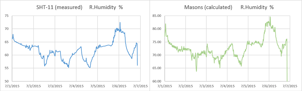


 (Note:I had to concatenate the date/time info into Excel’s time format to make this graph)