

In this tutorial, a logger is built using a 3.3v Moteino MEGA with a 1284p CPU @ 16Mhz, w 4K eeprom,16K SRAM for variables & 128K program space. Considerably more than the 328’s 1K eeprom, 2K ram & 32K progmem. Also has a spare serial port for GPS/NEMA sensors.
In the 2018 paper we tried to convey that it doesn’t matter which processor you use with our system as long as it’s supported by the Arduino IDE. The ATmega family includes several CPUs more capable than the humble 328p in the Pro Mini / UNO. In fact, some have suggested that the 1284 would have been a better choice right from the start, with full code compatibility once you account for the different port / pin mapping. We built several loggers around that chip early in the project, but at the time I was mostly just leaning on the extra memory to compensate for some fairly crude programming. As my skills improved, and I stopped using bloated sensor libraries, that problem went away. So it’s been a while since I needed anything more than the 328p. But we have a new project spinning up this year that calls for burst sampling of high-bit ADC channels, and we’ll need more SRAM to juggle that data with some fairly large buffer-arrays.
Dave’s protoboard build
For those who build from scratch, Dave Cheney shows one approach to starting with the raw chip. At the opposite end of the spectrum, Stroud Research Center’s Mayfly is a good combination if you’d prefer something ready-made. But I still have a a few Moteino MEGAs lying around, and this project has always followed the ‘middle path’ to enlightenment. So we’ll use one of those boards to demonstrate how easy it is to give our classroom logger a processor upgrade:
Add Screw Terminals to the Moteino: (click images to enlarge)
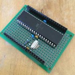
 Raspberry Pi expansion terminal boards are about $1 each, use 3mm pitch blocks from Nano kits. SPLIT Nano shields also work in a pinch, but you loose A4-A7 & D19-23 |
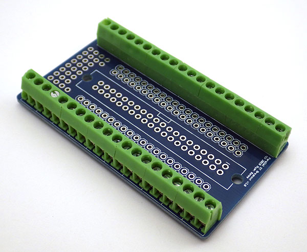 20 screw terminal ports per side, OR you could solder 2.54mm blocks directly to the MEGA. But they are not as robust for multiple reconnects during prototype experiments. |
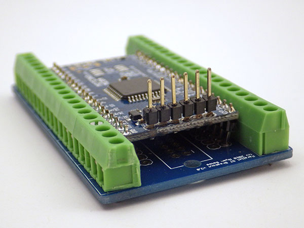 The Moteno MEGA from ‘just fits’ between the rails on the Raspberry Pi adapter. The ProMini XL fits on a Nano shield – but I like having all those extra I/O pins on the MEGA to play with. |
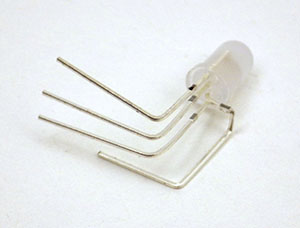
 Pins on the MEGA board need to be bent ‘slightly’ to align with the header holes on the Rpi shield. |
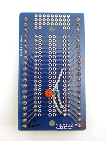 10 / 3 Meg divider to track battery voltage |
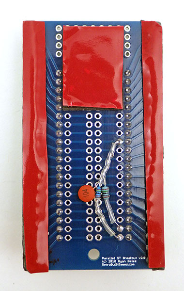 Two layers of 30lb double sided foam tape |
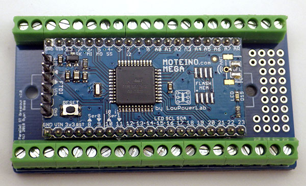
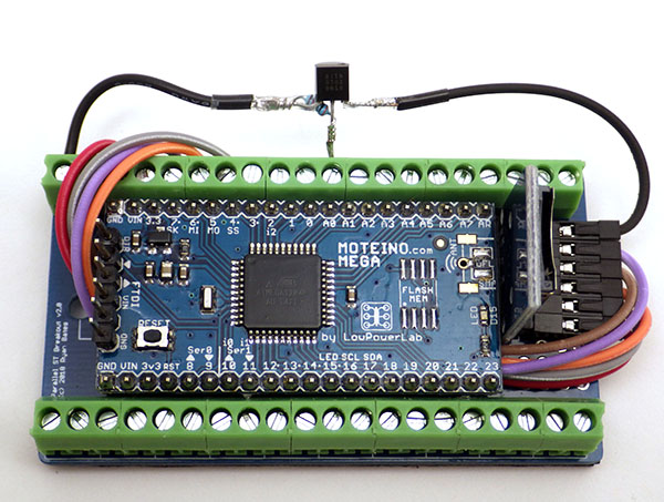
This is the basic version of the MEGA, but it’s also available with flash & radio transceiver options. LowPowerLabs also sells the Current Ranger – an extremely useful tool for checking the sleep current on my loggers. The shiny surface is due to the conformal coating we put on all our components. Clear nail polish also works once you’ve cleaned all the flux.
At the time of this writing there are a few 1284 boards on the market: the Moteino MEGA , the Megabrick, the Dwee, and the ultra compact Pro Mini XL. Other projects sporting the chip seem to pop up regularly, though few seem to last very long. This is a shame because 1284 has enough juice to do single-chip emulation of early 8-bit computers. But perhaps the chip never really caught on in Arduino-land because few beginners need that much capability. Sustained interest from dedicated makers means that some version, or at least DIY instructions, will will be available as long as the chip is in production. If I had to, the terminal expansion board I’ve used here would let me build one of those from the raw chip & a few passives. The trick would be making templates for the boards.txt and pins_arduino.h, and finding a bootloader that matches the system clock.
Component Prep & Logger Assembly:
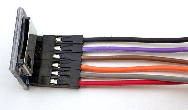 Black =GND, |
 Foam tape holds the Dupont jumpers together & provides accidental contact protection on the header pins. 3.3v system lets you connect the SD card directly |
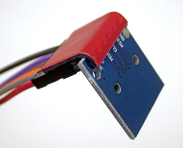
 Place the SD module to one side, leaving room for wire pass-through under MEGA Board. Note:a 10k pullup on the CLocK line was removed because mode0 sleeps low |
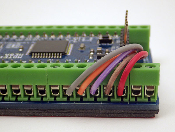
 Route all but the GND wire under the main board |
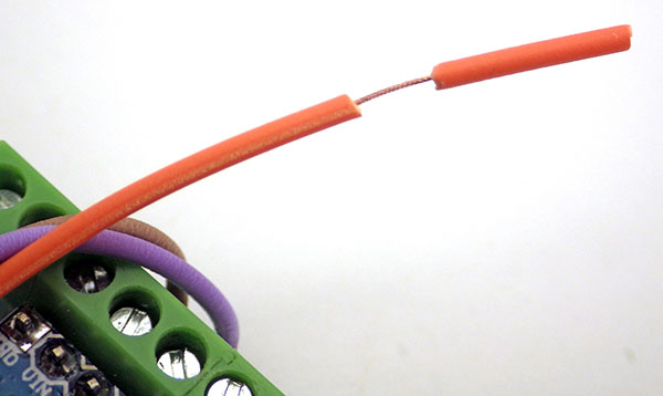 Score the insulation at ~15mm, and ROLL THE INSULATION between your fingers to TWIST the thin 30AWG strands together. |
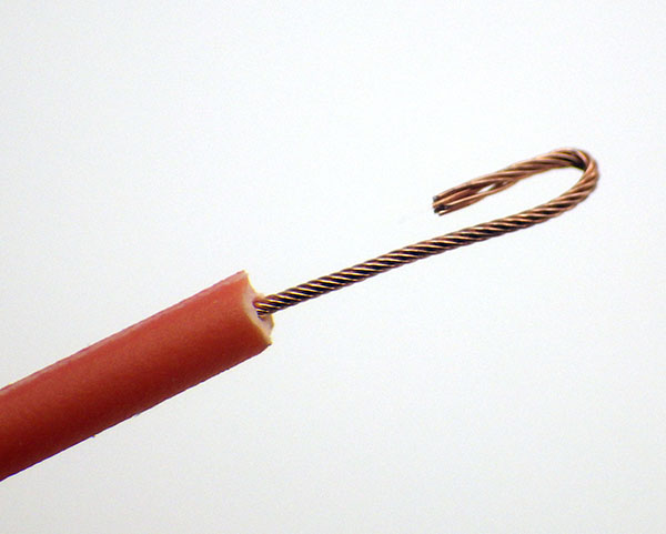 Add a 5mm ‘hook’ to provide more wire under the screw terminal contacts |
 SD card connections: |
 SD power is controlled by switching the GND line with a TN0702 logic level mosfet on D0 -> After <- SPI peripheral is disabled & all SPI bus lines are pulled up.
|
 Diffused common cathode RGB w GND pin bent to identify. No limit resistor is needed if you use INPUT_PULLUP to light each color channel. |
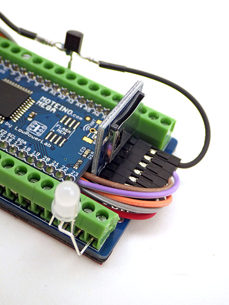 Any 4 unused pins would work for the indicator. |
 We add NTC thermistors to all of our builds & read them with the Input Capture unit on D14.
|
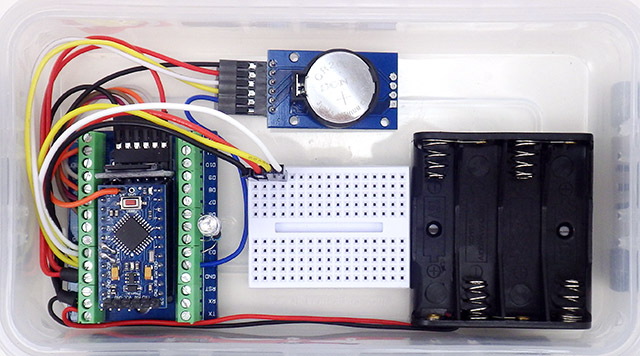
 Attach the GND wires before putting the MEGA into the Plano 3440 stowaway box being use as a housing. |
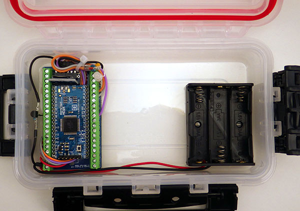 Here using 3xAA to supply the MCP1700 reg. on the MEGA. For unregulated builds, I use 2x Lithium AAs with flat discharge curves. |
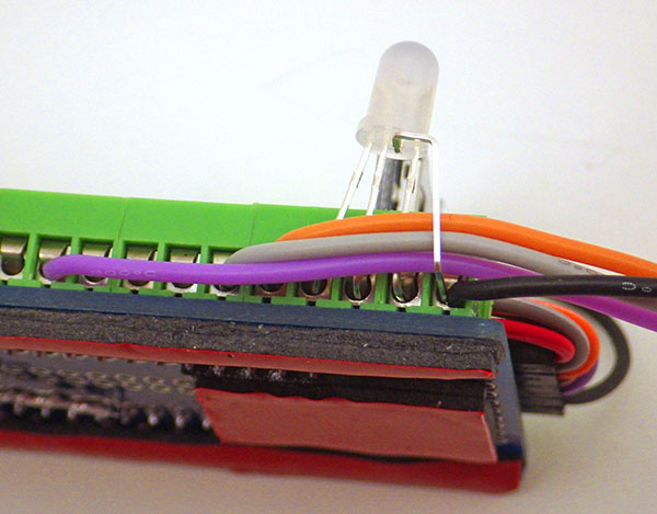
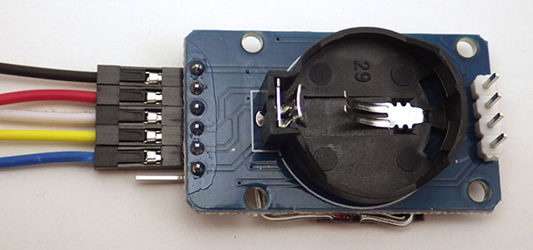 Blk(GND), Red(3.3v), White(SDA), Yellow(SCL), Blue(SQW) with Dupont pin headers added to the cascade port. 32K is not used as our power-mod disables that output. |
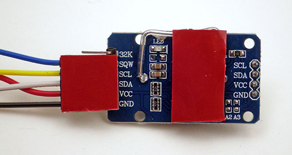 The DS3231 Vcc pin is clipped to force battery power & 1N1418 isolates the coin-cell (see end of the RTC post for details on this power-saving modification) |
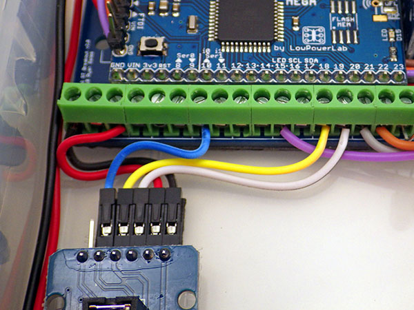 SCL=>D16 (yellow), SDA=>D17 (white), & |
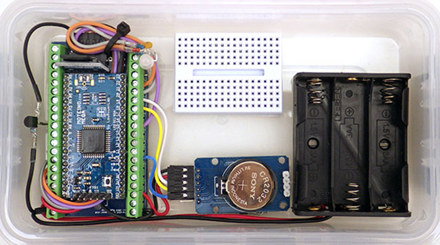 170 tie point breadboard completes assembly. I2C bus is tapped from the RTC modules 4-pin cascade port. |
 For comparison, here’s a regulated Pro-Mini based build from 2019 . In 2020 we switched the 328p builds to 2xAA with no regulator. |

The Moteino MEGA also makes Aref available (purple). Setting that to the internal1.1v bandgap gives you a reference voltage with thermal stability similar to a T431 provided you leave the ADC running long enough to stabilize the cap on aref & account for the internal resistance.
Now all I have is a bit of code tweaking to change the I/O in the codebase so those commands match the Moteino’s pinmap.
To complete the trim on this prototype I’ve added a 16-Bit ADS1115 (I’ll be giving that ADC a serious workout soon & will post any interesting results). Pinning the add-on module vertically preserves space on that tiny breadboard. With the ADS I won’t be using the internal ADC for much other than battery tracking. However analog pins will safely tolerate mid-range voltages which cause serious leakage problems on normal digital I/O pins. This lets you use a resistor bridge for scaled ranging techniques.
With all that extra memory to play with I’ll finally get to try some graphing libraries with that OLED – a luxury I can’t usually afford with ProMini based builds (though tiny plotter works in a pinch). And rumor has it that you can bit-bang I2C on ‘any’ GPIO pins, driving SSD1306 displays up to 10 frames per second. We have plenty of I/O lines to spare now for those experiments.
All of Atmels ‘-P’ variants have low power modes, and the logger shown here sleeps below 20μA (without the OLED, which draws ~25uA while sleeping) – that’s the about the same as I usually get with the 328p based units. The 1284 draws more runtime current (~17mA), but you can reduce that considerably by throttling the system with a prescaler. If you then accelerate the I2C bus by the same factor with TWBR, your sensors are none the wiser. In fact I’ve had no problem polling the 1115 with the system clock brought all the way down to 62.5 Khz with clock_prescale_set(clock_div_256);
I guess the last thing on my list is a name for this beast. I had been thinking of calling it the ‘MEGA pearl’, but a quick google search convinced me otherwise. So I’m open to suggestions.
Addendum 2020-05-12:

There are also 2650 (not-P) based options between $10-$20. The board shown above has double rows, so you’re stuck using straight pin headers unless you put 0.1” terminal blocks both above AND below. Plenty of ports there for hexapods, gigantic LED displays, musical instruments, or perhaps a game of chess. It is somewhat hard to find these boards at 3.3v 8mhz.
Well that didn’t take long: a few have already pointed out that I missed the Microduino Core + in the ‘currently available’ list. I’m sure there’s more so I’ll add them if I hear about others with a physical footprint that’s small enough to work as a drop-in replacement with the student build. I skipped the 644p in the preamble, but it’s another good low-power option if you are looking for more program memory. The 1284 is pin compatible with the 644, ATmega16, ATmega32 and probably a lot more.
Now that I’m playing with the 1284 again, I’ll also post any interesting projects I come across using these more powerful processors, such as this acoustic impulse marker or this body fat analyzer.
Addendum 2020-05-21: Using the ADS1115 in Continuous Mode for Burst Sampling
As promised, here’s a first look at that ADS1115 ADC module. For day to day tasks, it’s already something of a work-horse for Makers. But I wanted to push it out to the max settings to see if it’s ready for some typical research level applications. The answer is a tentative yes, but only at the fastest 860 sample per second speed. And with small signals EMI is more of a problem than the limitations of the ADC itself. I’m sure that’s not news to the analog hardware hackers out there, but I’m kind of a digital kid who’s still learning as I go along.

Pingback: Building an ATmega 1284p based data logger – gStore
Pingback: MoteinoMEGA based Data Logger | LowPowerLab
Pingback: Building an ATmega 1284p based data logger - Electronics-Lab
Could you provide a bit more detail on how to use the NPN mosfet to control power on the SD. My question is related to the software. Do I need to set all the SPI pins to input before I switch off the ground to the SD with the TN0702. Do I have to reinitialize the SD after I wake up from sleep? I did not see the code for this project posted in the article – I might have missed the link. Much thanks for a great post.
Yes, because I’m doing ground side switching ( which is not recommended, but seems to work fine for us ) all the pins get set to input+HIGH to prevent any current flow. You also need to disable & re-enable the SPI peripheral.
For more details see the post: