
The ‘solderless’ EDU build we released in 2020 provides remarkable flexibility for courses in environmental monitoring. However an instructor still needs to invest about five days ordering parts, testing components, and preparing kits for course being run remotely. (Although only 1/2 that is needed for in-person courses where the students pin & test the parts themselves.) While that’s not unusual for university lab subjects it’s a stretch for other instructors. And thanks to COVID shortages, modules that were only a buck at the beginning of the project might now set you back $5 each. So with all that in mind, we’ve continued development of a ‘lite’ version of our logger with the lowest possible prep. That new baby is now ready for release with data download & control done through the serial monitor window.
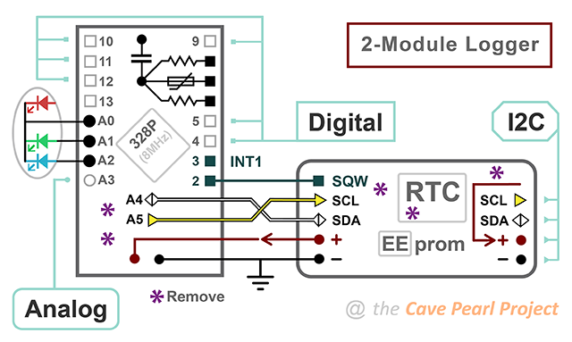
With just three core components our only option was to remove the SD card. Groundwork for this change has been in place for a long time in our research loggers, with sensor readings first getting buffered to the 4k to reduce the number of high-drain SD saves. Getting rid of those power hungry cards opened up the possibility of running the entire unit from the coin cell on the RTC module. But a power budget that small adds some complexity to the base code which must minimize CPU run-time and limit peak current.
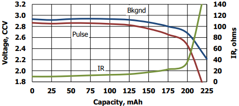
Most garden-variety chips have a lower operating limit of 2.7v – so a 3v Cr2032 can only fall about 300mv under load before triggering the brown out detection (BOD) circuit. Voltage droop changes over time because the internal resistance of a coin cell is only 10 ohms when new, but increases to 100 ohms by end of life. According to Maxell’s 1Meg-ohm (3.3µA continuous) discharge test, coin cells should stay at their voltage plateau until they deliver about 140mAh. In our testing, 200uF battery buffering capacitors can extend runtime up to 30% but this varied with the quality of the battery. Of course, if you can reach a year without the rail buffer, then you’ve probably filled the memory. So rail caps may only be necessary with high-drain sensors or in low temperature deployments where the battery chemistry slows. It’s not unusual to see a 50mv delta at the battery terminals for every 15°C change in ambient so a standard coin cell will not power the logger very long at temperatures very far below freezing.
However, theres only so much you can predict about system behavior in the real world – especially with stuff constructed from cheap modules carrying half a dozen unspecified components. So let’s just build one and see how it goes.
Jump links to the sections of this post:
- Prepare the RTC module
- Prepare the Pro Mini
- Joining the Two Modules
- Build video (3min Rapid-review)
- Code Overview: Setup & Main Loop
- Adding I2C Sensors
- Testing a New Logger
- A Discussion of Power Optimization
- Some Run Test Results
- Long Build video (1h with EEprom Upgrade)
- The e360 classroom variant (2023)
- Last Word
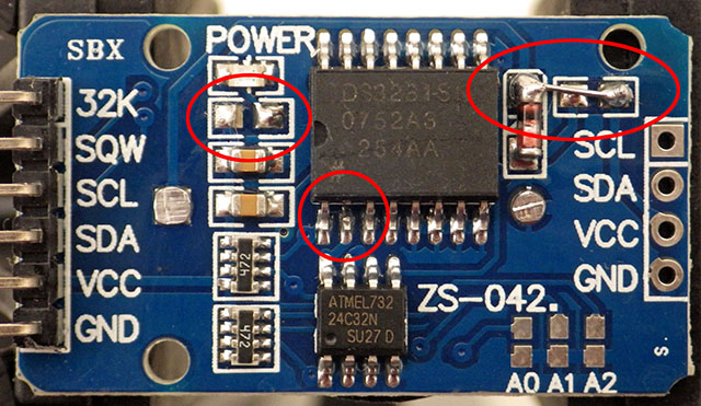
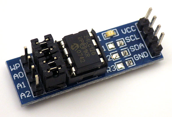
PREPARE the RTC module:


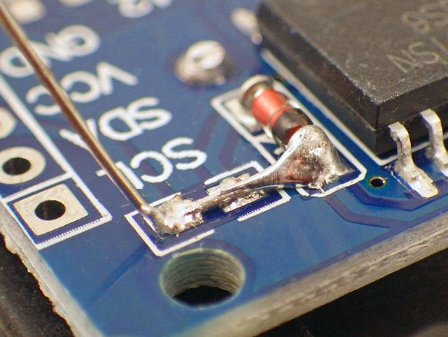
Running from Vbat depowers most of the logic inside the DS3231 and disables the 32kHz output (I usually cut away that header). According to the -M and -SN datasheets, but both RTC chips draw the same average of 3.0µA timekeeping battery current to keep only the oscillator, temperature compensation & comparator working. The default 4k EEprom draws between 20-40nA when not being accessed. Bridging VCC directly to Vbat also means a 3.3v UART will push some sub-milliamp reverse currents through an older coin cell. Despite dire manufacturer warnings that reverse currents beyond 1µA will heat manganese-dioxide/lithium cells until they explode, I’ve yet to have a single problem (or even any detectable warming) with loggers connected for many days during code development. Drift on these RTCs is usually a loss of ~3-5 seconds per month, but you can reduce this considerably by calibrating the DS3231 Aging Offset Register with a GPS module. The only annoying issue with these RTC’s is that, once enabled, the alarms continue to be generated forever unless you set an ‘unreachable’ next alarm time, or shut down the main oscillator completely.

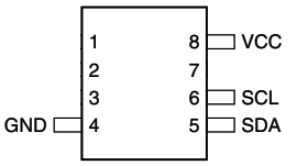
OPTIONAL: Add another EEprom to the RTC module
With a practiced hand you can add more EEprom memory right onto the RTC module. 64k is the sweet spot for single sensors generating 2-byte integers because they can store ~340 days of data at a 15min. interval. Each additional EEprom adds 0.2 to 0.4µA to the loggers overall sleep current. 64K’s are about $1 up to 256K chips selling for about $3.50 at Digikey. AT-series EEproms larger than 64k, show up on the I2C bus as multiple 64k chips.

PREPARE the Pro Mini:
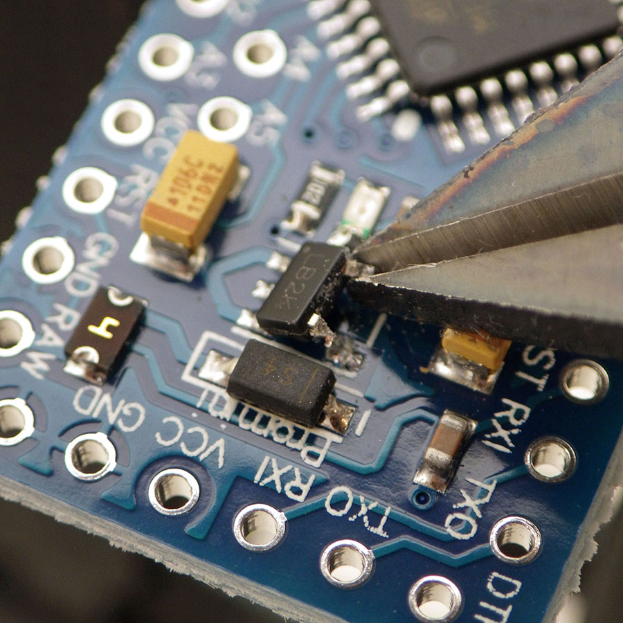

An Arduino Pro Mini continues at the heart of our loggers because it is still the easiest low-power option for projects that aren’t computationally demanding. 328p’s normally sleep well below 1µA with the BOD turned off but 17µA with BOD left on. It’s worth noting that component level testing of the tiny sleep current on an isolated ProMini board requires stable battery power, as UART supplied voltages are too noisy for sensitive devices like a Current Ranger. You will occasionally get clones with fake Atmel chips that won’t go below ~100µA sleep no matter what you do.
At 8Mhz the ‘official’ lowest safe voltage for the 328p is 2.7v and the BOD cutoff circuit is always on while the processor is running. So you want to stop logging if the rail starts falling below ~2850mv. Keep in mind that there is wide range of actual brownout thresholds, from a minimum of 2.5v to a max. of 2.9v. So if you get a logger that consistently quits while the battery voltage is still high, you might want to check that units actual BOD trigger point with a bench power supply.

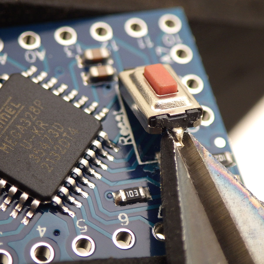
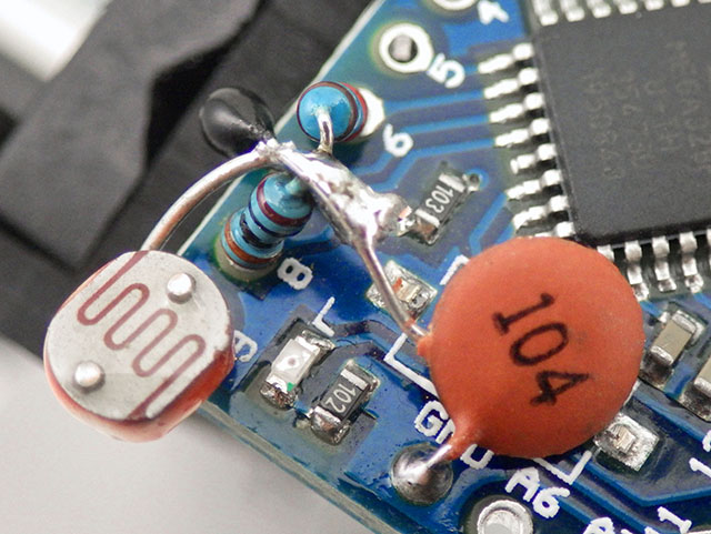
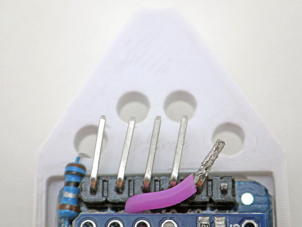
OPTIONAL: Add a Thermistor, LDR & Indicator LED
One of my favorite sensor combinations for this logger is an NTC thermistor & CDS cell which adds nothing to the sleep current. Range switching with two or more NTCs could also be done if the max / min resistance values of one thermistor can’t maintain your resolution requirements. We explained how to read resistive sensors using digital pins in 2019; so here I will simply show the connections. Add these passives to the Pro Mini BEFORE joining it to the RTC module, taking care not to hold the iron so long that you cook the components. Each [104] 0.1uF of capacitance you use in this circuit gives you about 3000 raw clock counts for the 10k reference resistor.


We created a how-to guide on calibrating thermistors which makes use of an online calculator to determine the equation coefficients. You should never expect the NTC you have in your hands to match the values provided by its manufacturer, but even if it did our method leverages the behavior of the ProMini itself as part of the measuring system. So there is no point buying expensive interchangeable thermistors – the cheapest penny-parts will do just fine. I add a thermistor to all my loggers (even if they will eventually drive I2C sensors) because a good way to test new loggers is to read the NTC at a short one-second interval until the EEprom has been completely filled a few times. After that burn-in you can be sure the core of the logger is reliable before adding other sensors.

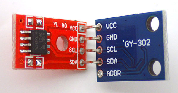
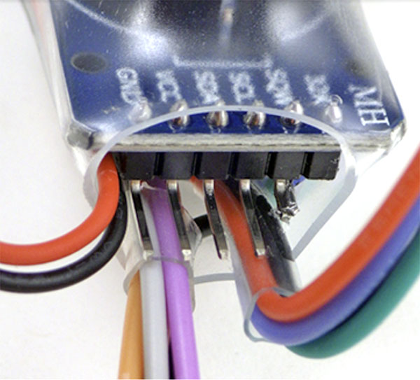
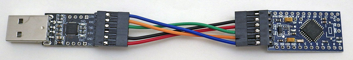
Join the Two Modules:
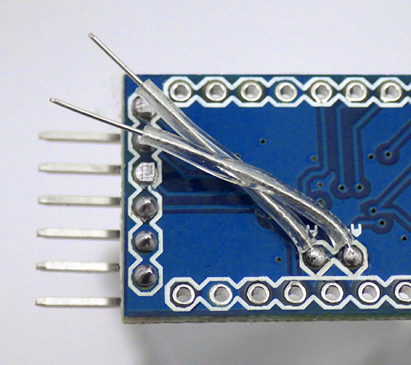
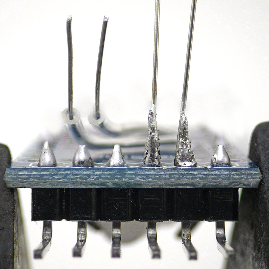

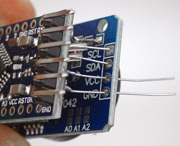
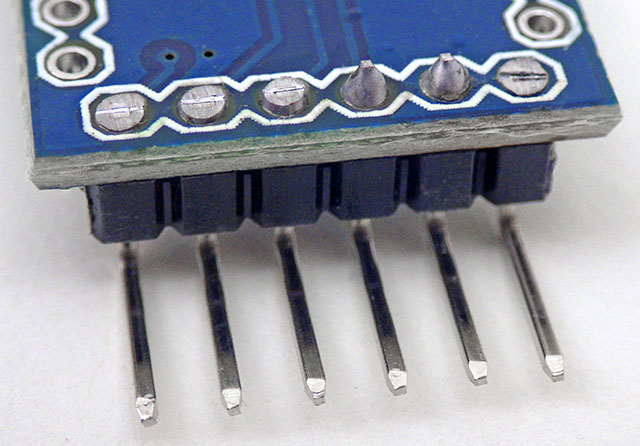
Carefully thread the four I2C jumpers through the RTC modules pass-through port.


The basic two-module combination usually sleeps around 1-2µA continuous. Most of that is the RTC’s timekeeping current as a 328p based ProMini only draws ~150nA in power-down (with regulator removed & BOD off) and the 4k eeprom should be less than 50nA in standby. If we assume four readings per hour at 5mA for 30msec, the battery life calculator at Oregon Embedded estimates a 220mAh battery will last more than 10 years…which is ridiculous. We know from the datasheet that the typical Ibat timekeeping current for the DS3231 is `700nA (dsheet pg7 with EN32KHZ=0 @3v) but TXCO temperature conversions bring the RTC average up to 3µA – which can’t be seen on this direct measurement. And there’s the battery self discharge of 1-3% per year. Perhaps most important there’s the complex relationship between pulsed loads and CR2032 internal resistance, which means we’ll be lucky to get half the rated capacity before hitting the typical 328p brown-out at 2.77v. A more realistic estimate would start with the assumption that the battery only delivers about 110mAh with our logger consuming whatever we measure + 3µA (RTC datasheet) + 0.3µA (coincell self-discharge). For conservative lifespan estimation we can round that all up to about 5µA continuous, with four 5mA*10millisecond sensor readings per hour, and we still get an estimated lifespan of about two years. So the most significant limitation on this logger is usually the EEprom memory. It’s worth noting that newer DS3232 variants of the RTC lets you push the TXCO corrections out to 512 seconds. This lowers the average RTC standby to about 1µA -if- you are willing to spend $10 for the RTC chip alone on DigiKey.
Build video: ( 3 minute rapid review)
The Code: [posted on Github]
In 2023 the logger base code was updated to match the newer the e360 model, being essentially identical except for the changes required for the alternate NTC and LED connections. The code requires the LowPower.h library for AVR to put the logger to sleep between readings and this can be installed via the library manager.
One important difference between a coin cell powered logger and our older AA powered models is that the battery has a high probability of being depleted to the point of a BOD restart loop. (which causes rapid flashing of the D13 LED) So we use a multi-step serial exchange in Setup() to prevent data already present in the EEprom from being overwritten by an accidental restart.
Setup()
Purple callouts on the following flow diagrams indicate the places that would need to be altered to add a new sensor to the base code. If all you do is enable sensors via defines at the start of the program you won’t have to deal with the code that stores the data. However to add a new sensor you will need to make changes to the I2C transaction that transfers those sensor readings into the EEprom ( with matching changes to the sendData2Serial function that reads them back out later).
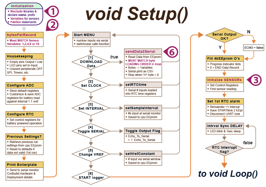
A UART connection is required at start-up so those menu-driven responses can occur through the serial monitor in the IDE. These have 8minute timeouts to avoid running the CPU too long during unintentional restarts. The menu sequence can be re-entered at any time simply by closing & re-opening the serial monitor window: This restarts the Pro Mini via a pulse sent from the UARTs DTR (data terminal ready) pin.
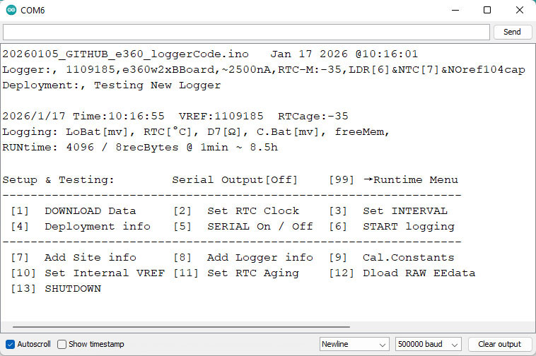
The first menu option asks if you want to download the contents of the logger memory to the serial monitor window. This can take up to 2 minutes with 256k EEproms at 500000 baud, which is the fastest rate an 8MHz ProMini can reliably sustain. Then copy/paste everything from the IDE window into an Excel sheet. Then below the data tab, select Text to Columns to separate the data fields at the embedded commas. Or you can paste into a text editor and save as a .csv file for import to other programs. While that process is clunky because the IDE’s serial interface doesn’t export, everyone already has the required cable and data retrieval is driven by the logger itself. And yes, the exchange could also be done with other serial terminal apps like PuTTY with logging turned on, CoolTerm, or Termite with the ‘logfile’ filter. You can also redirect Windows COM port output to a file, although it seems limited to only 19k baud. These options may be required on builds with large memory expansions as the IDE serial monitor starts to forget the initial data in it’s buffer after displaying about 100,000 lines. I have successfully used Termite at 1,000K baud downloading an 8mhz logger, but when the amount of data gets large the ProMini starts limiting you to an effective 500K baud. Functions like itoa() before serial.print() or using Rob Tillaart’s splitDigits4 & splitDigits10 with serial.write() speeds things up considerably. In summary, 250k BAUD is stable, 500k is usually fine with occasional serial dropouts in a very long download, while 1,000k Baud exhibits frequent flaky behaviors with the IDE’s serial monitor. Those character dropouts don’t happen using Coolterm or PuTTY.
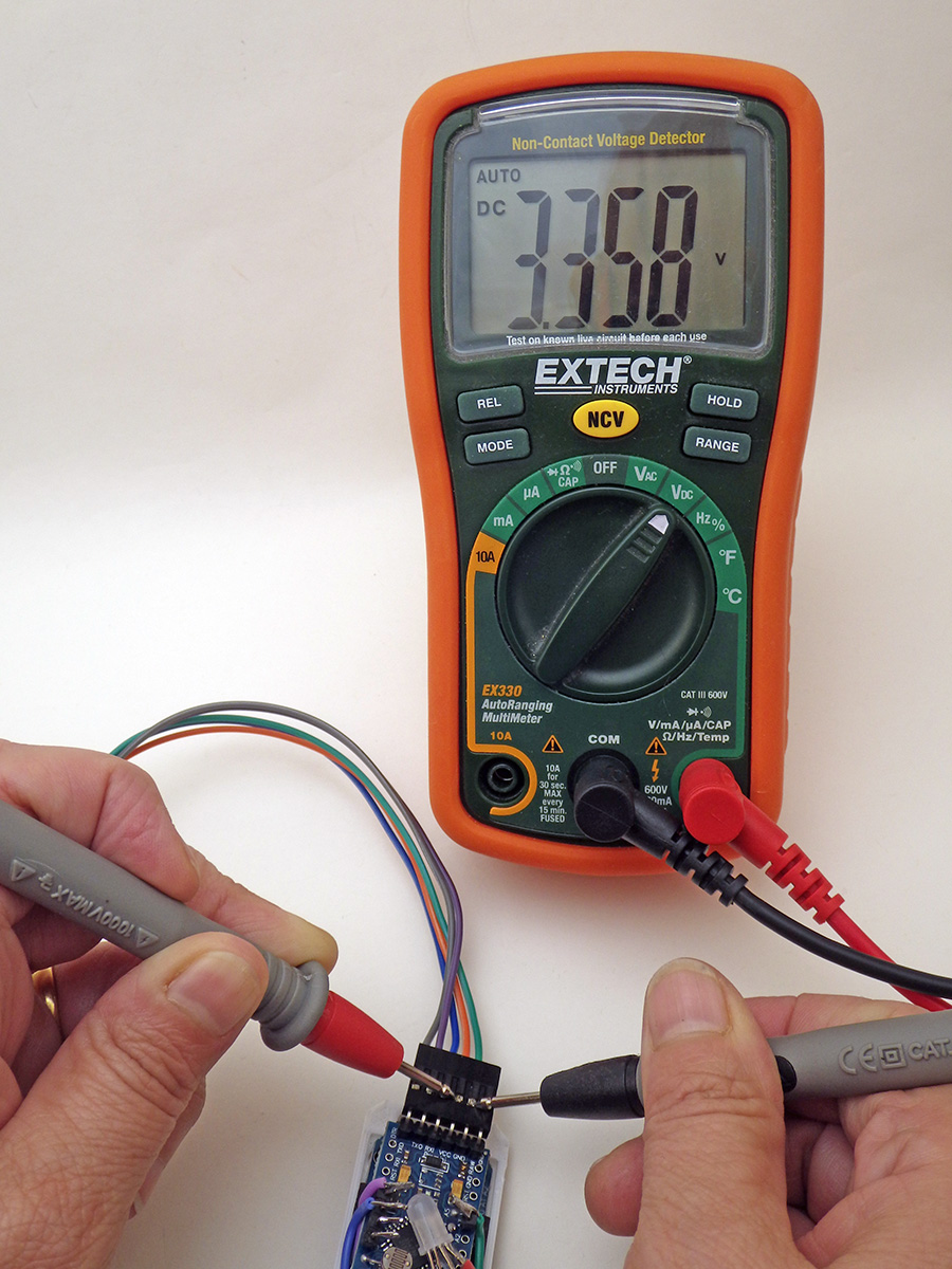
Vref compensates for variations in the reference voltage inside the 328p processor. Adjusting the 1126400 (default) value up or down by 400 raises/lowers the reported voltage by 1 millivolt. Adjust this by checking the voltage supplied by your UART with a multimeter while running the logger with #define logCurrentBattery enabled and serial output ON. Note the difference between the millivolts you actually measured and the current voltage reported on screen, and then multiply that difference by 400 to get the adjustment you need to make to vref for accurate battery readings. After you [7] Change Vref and enter the adjusted number it will be used from that point onward. Stop adjusting when you get within ±20mv.
After the start menu sequence the first sampling time is written to the internal EEprom so the timestamps for sensor readings can be reconstructed during data retrieval later by adding offsets added to the starting time. This technique saves a significant amount of our limited EEprom memory and all it takes is =(Unixtime/86400) + DATE(1970,1,1) to convert those Unix timestamps into human readable ones in Excel. It is important that you download the old data before changing the sampling interval via the startup menu option because the interval stored in EEprom is also used to reconstruct the timestamps. Valid sampling intervals must divide evenly into 60 and second-intervals can be set for rapid testing if you first enter 0 for the minutes.
No data is lost from the EEprom when you replace a dead coin cell and you can do the entire data retrieval process on UART with no battery in the logger. But the clock time should only be reset after installing a new battery or it will not be retained. If the time in the serial menu reads 2165/165/165 165:165:85 instead of 2000/01/01 after a power loss then there’s a good chance the RTC’s memory registers have been corrupted & the RTC module needs to be replaced. I’ve managed to do this to a few units by accidentally shorting the voltage to zero when the logger was running from a capacitor instead of a battery.
After setting the clock time and deployment parameters like the sampling interval, the logger will request the user to manually type a ‘start’ command before beginning a run. Only when that second ‘start’ confirmation is received are the EEproms erased by pre-loading every location with ‘Zeros’ which also serve as End-Of-File markers during download. The selected LED will then ‘flicker’ rapidly to indicate that the logger is ‘waiting’ until the current time aligns with the first sampling alarm before beginning the run.
Main LOOP()
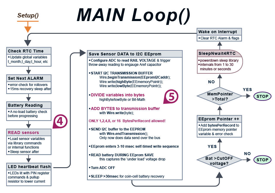
EEprom writes usually draw about the same 3mA current the ProMini draws during CPU up time. ‘Lowest’ battery voltage is checked immediately after the data transfer because an unloaded Cr2032 will always read nominal – even when it’s nearly dead. Timing of events at that point is critical because EEproms freeze if the rail voltage fluctuates too much while they are actively writing – so don’t change those LowPower.idle sections of the code! Also don’t run OLED screens during sensor readings or EEsaves because they are noisy as heck. Logger shutdown gets triggered at the end of the main loop if the EEprom save brings the rail voltage below the 2850mv systemShutdownVoltage or if the memory is full.
Adding I2C Sensors to the logger:
The minimum configuration for this logger can log the 0.25°C temperature record from the DS3231, index-encoded to one byte per reading. Approximately 4000 of these readings can be stored in the 4k EEprom on the RTC module. This works out to a little more than 40 days at a 15 minute sampling interval.

The 4K AT24c32 on the RTC module fills rapidly with sensors that generate 2 or 4 byte integers. An easy solution is to combine your sensor module with 32k (AT24c256), or 64k (AT24c512) chips so the sensors bring the extra storage space they will need. These EEprom modules can usually be found on eBay for ~$1 each and after you update the EEpromI2Caddr & EEbytesOfStorage defines at the start of the program, all AT series chips will work with the same code as the default 4k.
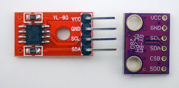

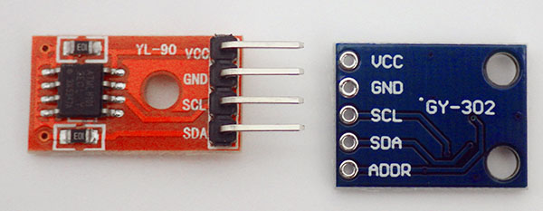

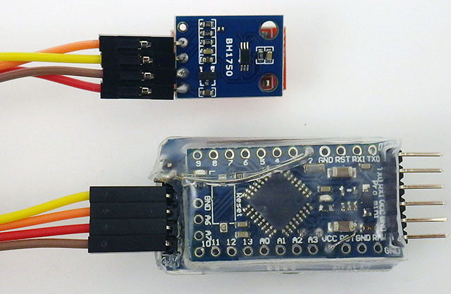
In addition to the NTC / LDR combination, support for both of the sensors shown above is included in the code on Github although you will need to install hp_BH1750 and BMP280_DEV with the library manager to use them. Sensors are enabled by uncommenting the relevant defines at the start of the program. No matter what combination of sensors you enable, the total bytes per record must be 1,2,4,8 or 16. Otherwise you will get a repeating error at download because trying to save data beyond a hardware page-boundary inside the EEprom over-writes previously saved data at the start of that same page/block.
I2C devices are usually rated to sink about 1mA which on a 3v system would require 3300 ohm pullups. This means you can leave the 10k’s on those sensor modules to bring combined bus pullup ( incl. 4k7 on the RTC & 35k pullup on the ProMini pins) to 2930 ohms, which is close to the 3.3k ideal. The open-drain implementation of I2C means that adding more capacitance to the bus will round off the rising edges of your clock and data lines, which might require you to run the bus more slowly with multiple sensors or with longer wires to your sensors. In those cases you can drop the total bus pullup to 2k2 to offset the capacitance.
You must use low power sensors with a supply range from 3.6v to our 2.7v BOD cutoff. A good sensor to pair with this logger should sleep around 1µA and take readings below 1mA. You are more likely to find these no-reg sensor modules with low power operation at Sparkfun or on Tindie, than you are on eBay/Amazon. A coin cell simply doesn’t have enough power to supply a high drain CO2 sensor or GPS unless you take heroic measures. Sometimes you can pin-power sensors that lack low current sleep modes although if you do that be sure to check if that creates current leaks in other places such as pullup resistors or the I2C bus may go into an illegal state (idle is supposed to leave SCL & SDA lines high) requiring a power reset of all the sensors on the bus. Choose sensor libraries which allow non-blocking reads so you can sleep the ProMini while the sensor is gathering data and replace any delay() statements in those libraries with 15msec powerdown mode sleeps.
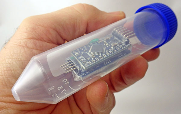
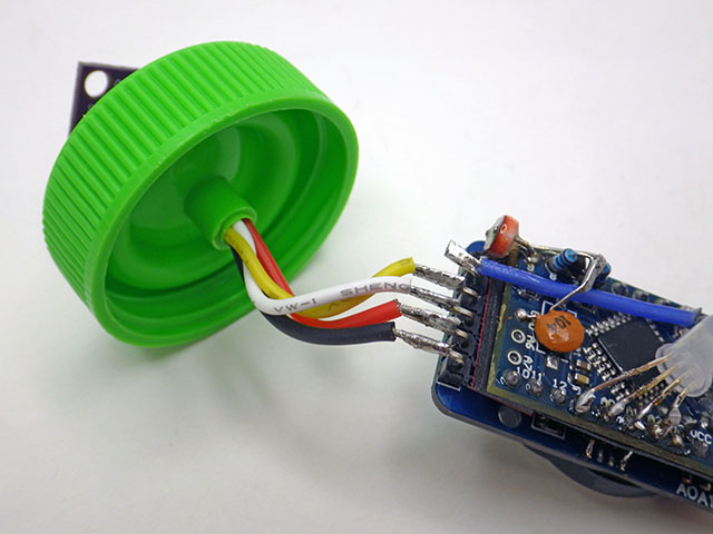
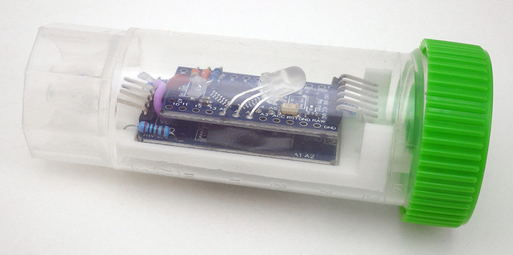
30ml self-standing Caplugs from Evergreen Labware are a good housing option because they have a brace in the cap that just fits four 22gauge silicone jacket wires. The ‘non-sterile’ versions with separate caps are much cheaper to buy than the sterile ones. The outer groove in the lid provides more surface area for JB-weld epoxy, giving you an inexpensive way to encapsulate external sensors. 1oz / 25ml is enough to cover about five sensors. Then clear JB weld can be used as a top-coat to protect optical sensors.


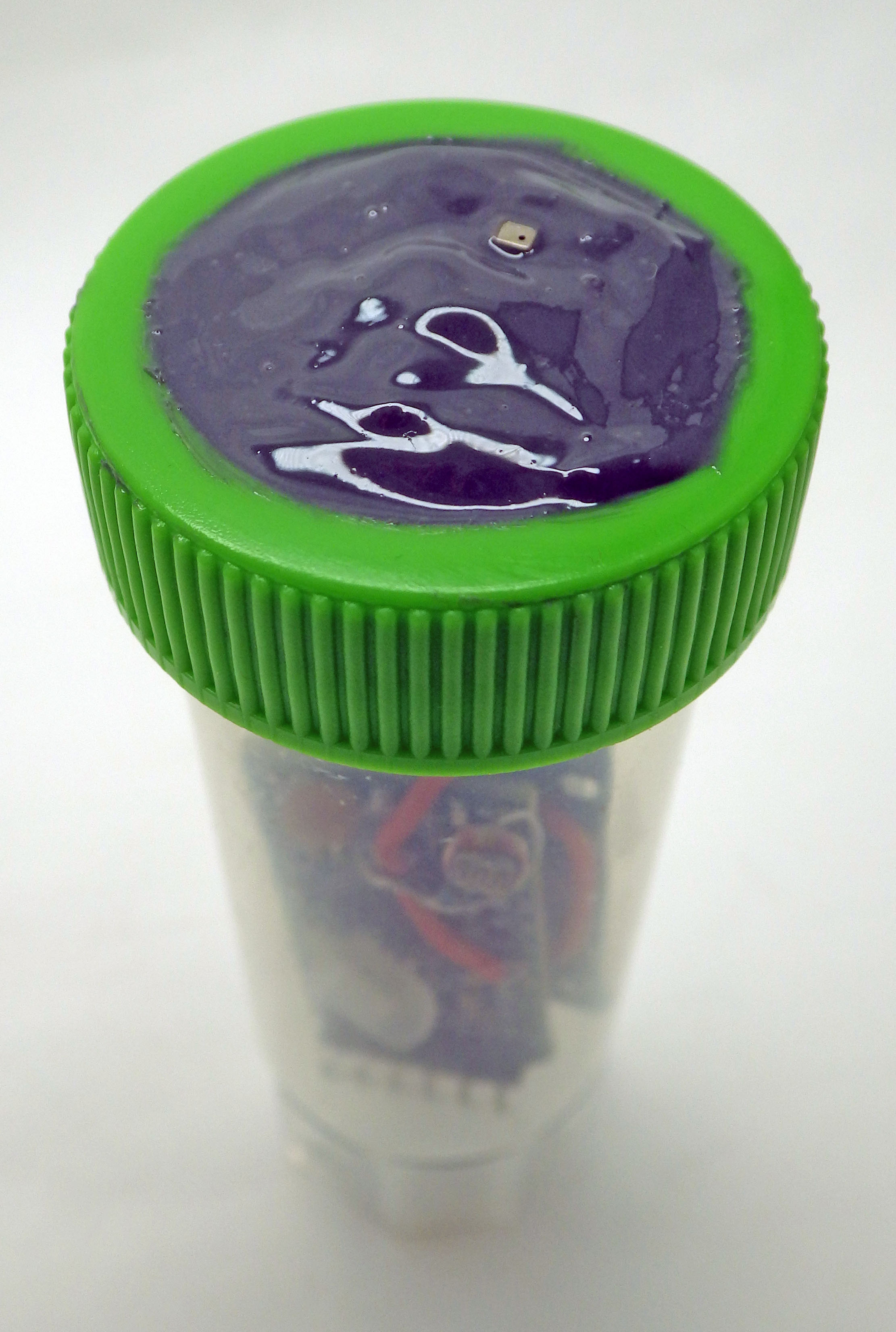
We’ve done pressure tests to 45psi and these tubes can be deployed to ~20m depth, although we don’t yet have any data yet on how long they will endure at that pressure. These housing tubes should be replaced every three months if they are exposed to sunlight because UV makes the plastic brittle. Adding a very small amount of silicone grease to only the upper edge of the tube before closing improves the seal with the lid but don’t add too much or the threads will slip. Holes drilled through the bottom stand enable zip-ties to secure the logger. In our cross calibration of a Bh1750 Lux sensor to measure PAR (Photosynthetically Active Radiation) , we wrapped the body tubes with 2″ aluminum foil tape to reduce heat gain inside the body tubes.
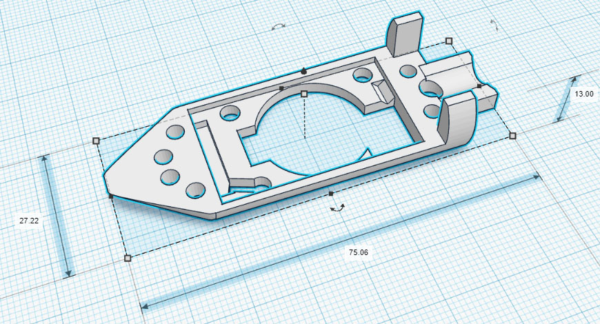
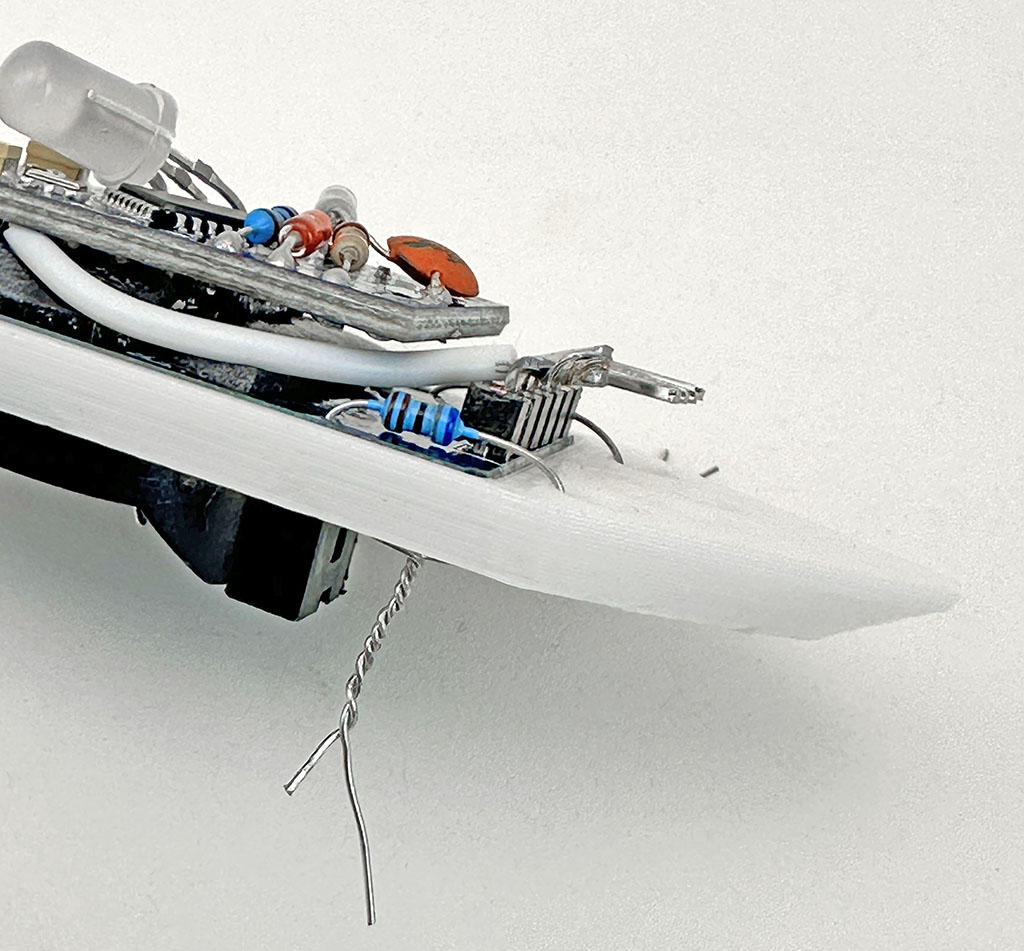
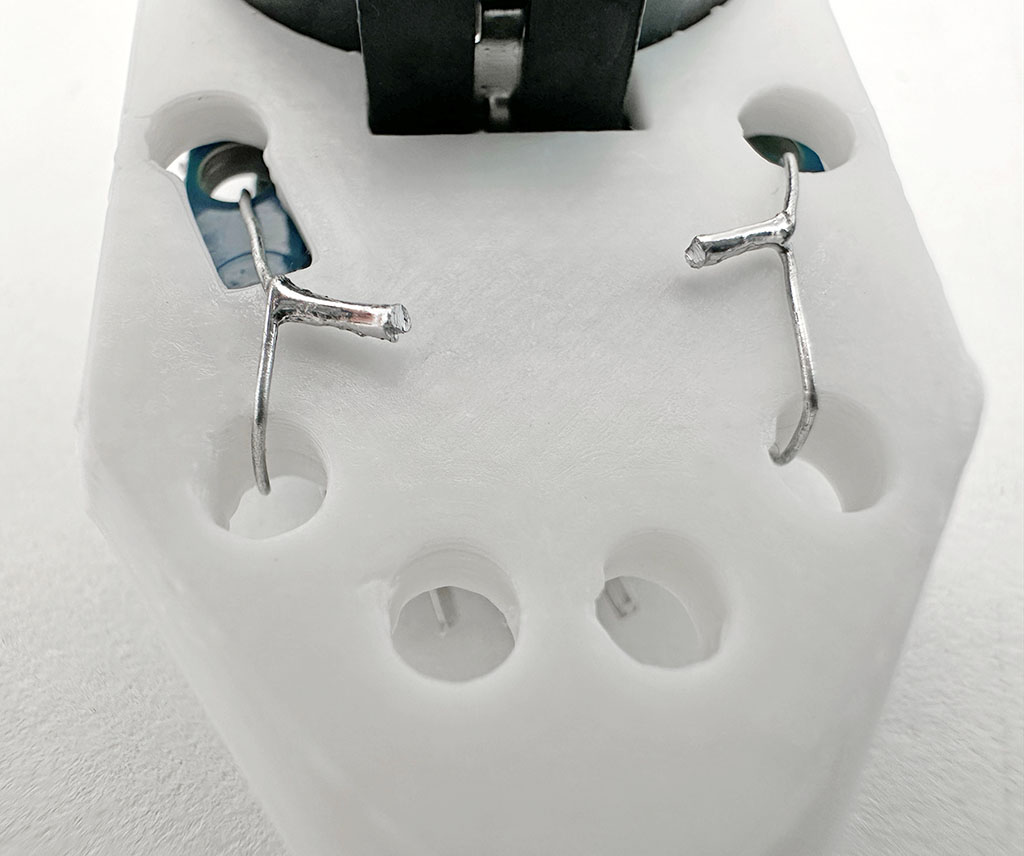
We have produced small printable rails for the 30ml tubes often used with this two module logger. So here is a link to that shared model on Tinkercad. That internal rail & an external mounting bracket is posted at Github. The easiest way to secure the logger to these rails is with a drop of hot glue from the underside but I usually twist and solder the legs of a scrap resistor as the tie as I have lots of these lying around:
For deeper aquatic deployments, you could use a stronger PET preform for the enclosure. These have very thick walls because they are the blanks that are thermally blow-molded to create soda bottles. You will need to find ones larger than the standard 2L bottle preforms which have an internal diameter of only 21mm. This is just a bit too tight for the RTC module. The 30ml centrifuge tubes shown above have an internal diameter of 26-27mm.
Testing Your New Logger
Make at least two machines at a time. I usually build in batches of six, and for every dozen at least one usually ends up with some kind of issue like an RTC temp. register outside the ±3°C spec, or a ProMini with one of those fake 328p processors that draws too much sleep current. Having more than one logger makes it easy to identify when you’ve got an a hardware problem rather than an error in your code. Even then, no unit is worth more than an hour of troubleshooting when you can build another one in less time. Seriously! The part cost on these things is well below $10, which is often less than you’d pay just to replace the battery on other loggers. This also applies to maintenance: just run till it fails and then replace it. In our experience, most inexpensive sensors have a reliable lifespan of less than two years in the field.
A good general approach to testing any DIY build is to check them with a doubling schedule: Start with rapid UART tethered tests via the serial monitor at second intervals, then initial stand-alone tests for 1,2,4 & 8 hours till you run overnight, followed by downloads after 1day, 2days, 4days, 8days, etc. For those initial burn-in tests, set the interval short enough that the entire memory gets filled. Valid sampling intervals must divide evenly into 60 and second-intervals can be set for rapid testing if you first enter 0 for the minutes.
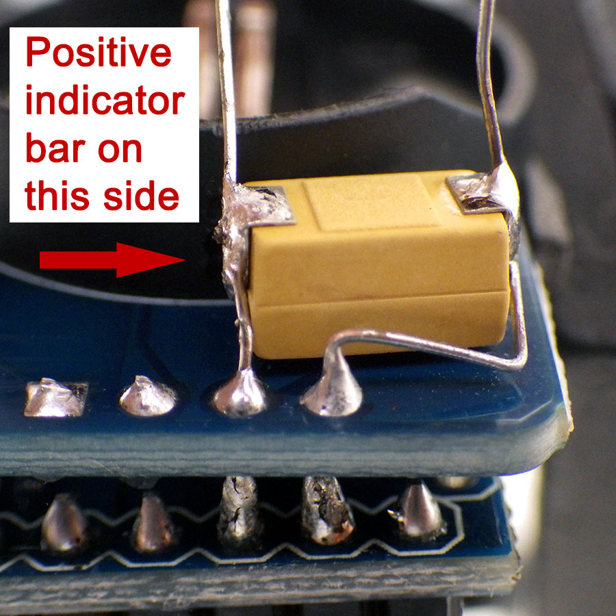
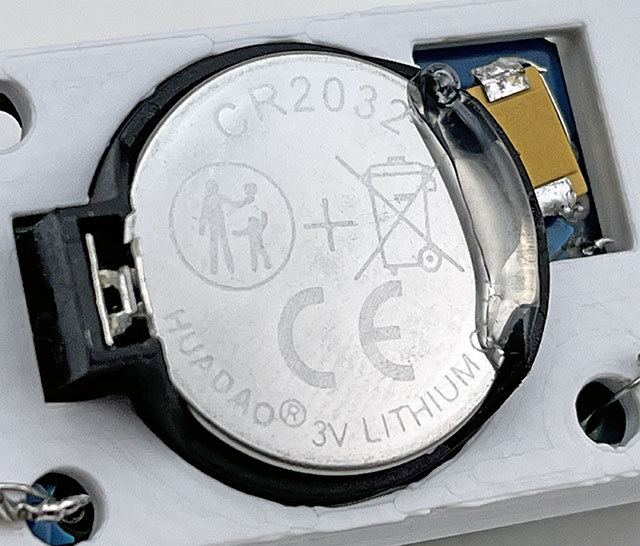
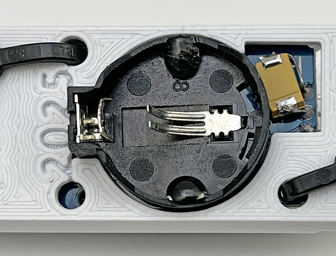
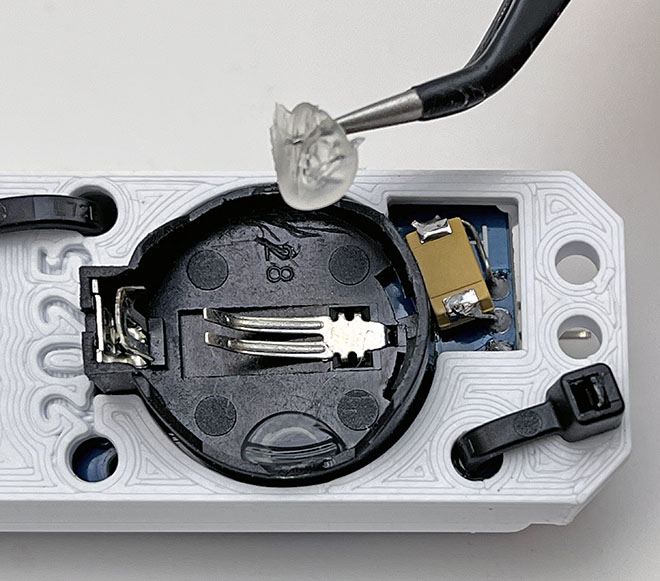
Weak battery springs, or sloppy plastic molding on the RTC module can make a logger vulnerable to bumps that disconnect power (causing the logger to shut down). Most of the time the battery can be secured reasonably well by simply by laying a line of hot glue along the top edge opposite the positive contact spring. This is easily removed after the deployment:
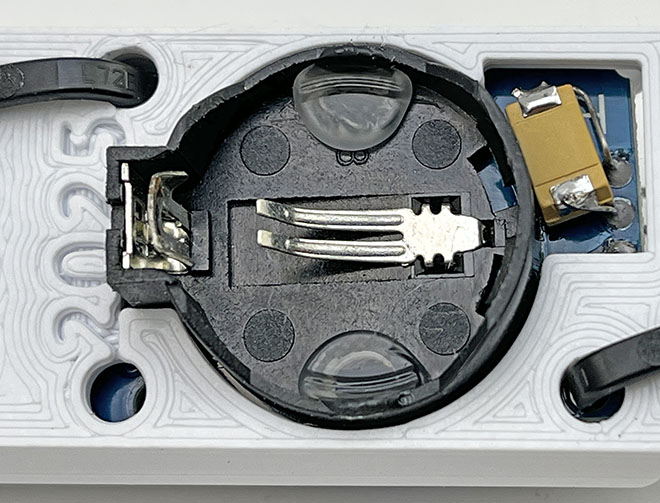
Occasionally you get an RTC module with a battery holder loose enough that the coin cell can actually rock from side to side, pivoting on the negative contact spring. This more extreme loose battery case requires two drops of glue under the coincell:
The shape of the battery burn-down curve during your pre-deployment testing is and excellent predictor of reliability! But to use that information you need to be running several identical machines at the same time, and start those runs with fresh batteries. I use the cheapest batteries I can get for these tests, knowing the better quality batteries I use on deployment will last much longer.
Remember that eBay/Ali/Amazon sensor modules are cheap for a reason and it’s not unusual to see 20% of them rejected for strange behavior or infant mortality. So huddle test each batch to normalize them. Relative accuracy spec for the BMP280 is supposed to be ±0.12 millibar, but when I run a batch of them side-by-side I usually see ±4 millibar between the records. Cheap BMEs sometimes refuse to operate with it’s individual RT/T/Pr sensors set at different oversampling levels, and at the highest resolution (16x oversampling) that sensor may draw more than your power budget can sustain over a long deployment. Real-world installation inevitably exposes the logger to condensing conditions. Sensors with a metal covers (like the BMP/E series) will experience internal condensation at the dew point. Moisture creep is the largest cause of data loss on the project after theft/vandalism. So cleaning leftover flux from all parts with cotton swabs + 90% isopropyl alcohol before & after assembly is always worth your time. So is conformal coating and you can use clear nail polish for that if silicone coatings are hard to find.
And all the other quid-pro-quos about vendors apply: Split your part orders over multiple suppliers with different quantities, ordered on different days, so you can isolate the source of a bad shipment and/or identify suppliers that are OK. Don’t be surprised if that batch of sensor boards you ordered transmogrifies into a random delivery of baby shoes. Amazon is often cheaper than eBay and AliExpress is 1/4 the price of both. Trusted suppliers increase part costs by an order of magnitude but that may still be worth it if you don’t have time for enough test runs to eliminate the duds.
Power Optimization on this Data Logger:
A (relatively high) average sleep current of ~5µA*86400 sec/day would use ~432 milliAmpseconds/day from a Cr2032 that can provide roughly 360,000 mAs of power [100mAh] on its main voltage plateau . Any power saving strategy must be weighed against this daily amount to determine if the complexity it adds to your code will deliver a proportional increase in operating time. I rarely see a sensor sample reading use more than 1 milliamp-second of power – even with relatively high drain sensors like the BME280. So most of the power used by this logger is due to the DS3231 RTC’s 3µA timekeeping current which can not be changed but battery voltage droop during peak current events is usually what triggers the low voltage shutdown and that is affected by code execution.
8MHz ProMini boards draw about 3.5mA when running at 3v. Slow functions like digitalWrite() and pinMode() are replaced with much faster port commands wherever power and/or timing are critical. Pin states, peripheral shutdowns (power_all_disable(); saves ~0.3mA) and short sleeps are used throughout for battery voltage recovery. Waking the 328p from those powerdown sleeps takes 16,000 clock cycles (~2milliseconds @8MHz +60µS if BOD_OFF) and but the ProMini only draws ~300µA while waiting for the oscillator to stabilize. These wakeups only use about 1mAs/day.
The original code released in 2022 used CLKPR to bring the ProMini down to 1MHz (lowering runtime current from 3.5mA to ~1.3 mA) however testing later revealed that the total energy cost per logging event actually increased slightly when the system clock was divided. In addition, I came across several EEproms that would freeze if I lowered the system clock to 1MHz during save. So I have removed the CLKPR calls to make the codebase more portable. I also found that the startup-time also gets multiplied by the CLKPR divider. This might be the only documentation of this on the web, so I’m leaving this information here – even though CLKPR is no longer relevant to the logger:
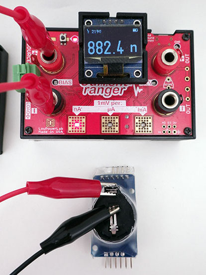
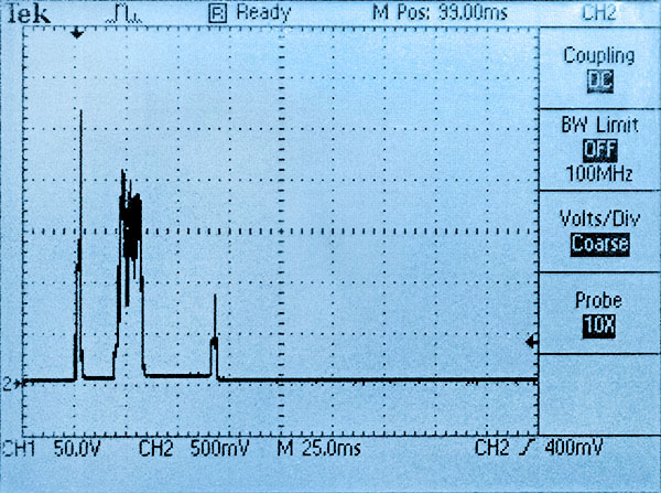
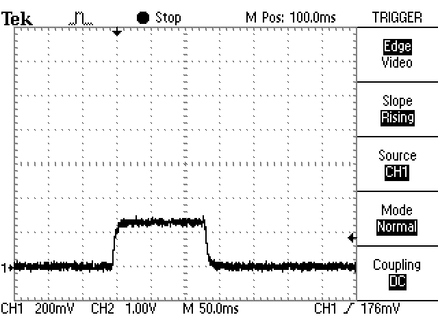
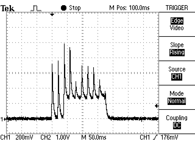
( Note: For the following images a Current Ranger was used to convert µA to mV during a reading of the RTC’s temperature register at 1MHz. So 1mV on these oscilloscope screen shots = 1µA is being drawn from the Cr2032 )

Using the 328s internal oscillator to save power is a non-starter because it’s 10% error borks your UART to the point it can’t upload code. Our ICU based timing method also needs the stability of the external oscillator.
That bridge between the coin cell and VCC means UART connection time probably is shortening battery lifespan a bit. Panasonic specifies: “the total charging amount of the battery during it’s usage period must be kept within 3% of the nominal capacity of the battery”, so it’s a good idea to remove the coin cell if you are spending an extended time on serial. But given our tight operational margin we can’t afford to lose 200mv over a Schottky protection diode. A typical solution would address this by ORing the two supplies with an ideal diode circuit but that’s not a option here as ideals usually waste some 10-20 µA. On a practical level it’s easier to just to pop in a fresh battery before every long deployment.
EEprom & sensor additions usually push directly measured continuous sleep currents to 2µA (so ~5 µA average when you add the RTC temp conversions) but that still gives a >1 year estimates on 110mAh. With all due respect to Ganssle et al, the debate about whether buffering caps should be used to extend operating time is something of a McGuffin because leakage is far less important when you only have enough memory space for one year of sensor readings. Even a whopper 6.3v 1000µF tantalum only increases sleep current by ~1µA. That’s 1µA*24h*365days or about 10 mAh/year in trade for keeping the system well above the 2.8v cutoff. That means we don’t need to lower the BOD with fuse settings & custom bootloaders. When you only service your loggers once a year, any tweaks that require you to remember ‘special procedures’ in the field are things you’ll probably regret.
Capacitor leakage scales linearly so use the Falstad simulator to see what size of rail buffer you actually need. Capacitors rated 10x higher than the applied voltage reduce leakage currents by a factor of 50. So your buffering caps should be rated to 30v if you can find them. The 220µF/25v 227E caps I tested only add ~15nA to the loggers sleep current and these can be obtained for <50¢ each. (& 440uF 10v caps leak around 25nA) High voltage ratings get you close to the leakage values you’d see with more expensive Polypropylene, Polystyrene or Teflon film caps and moves away from any de-rating issues. The one proviso is that as the buffering cap gets larger you will need to add more ‘recovery time’ in the code before the rail voltage is restored after each code execution block. Sleeping for 30msec after every I2C transaction is a safe starting point, but you’ll need a scope to really tune those sleeps for large sensor loads like you see with a BME280 at 16x oversampling. If moisture condenses inside the housing on deployment, and the logger mysteriously increases from 1-2 µA sleep current to something higher then replacing the tantalum rail buffering cap is one of my first diagnostic steps.
In the next three images, a Current Ranger converts every 1µA drawn by the logger to 1mV for display on the ‘scope. The last two spikes are transfers of 16-bytes into the 4K EEprom on the RTC module while the CPU takes ADC readings of the rail voltage. Note that our current code saves readings as a single event at the end of each pass through the main loop, but I forced multiple large saves for this test to show the effect of repeated pulse-loads:

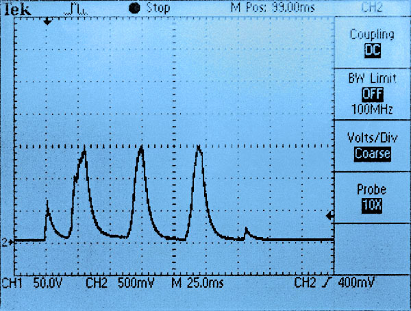
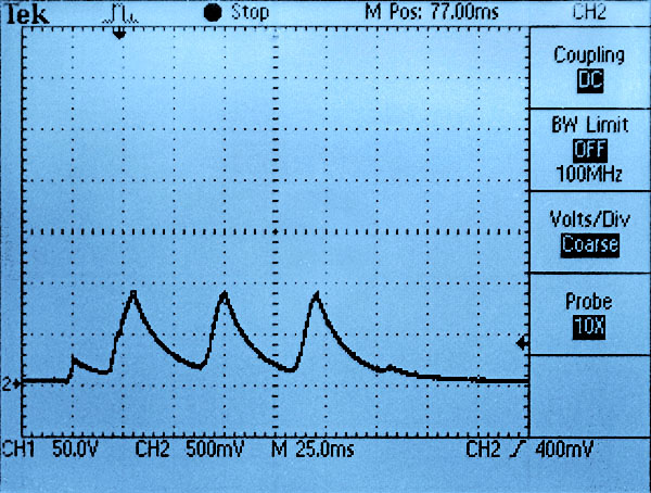
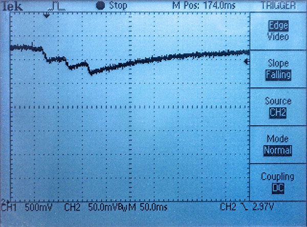
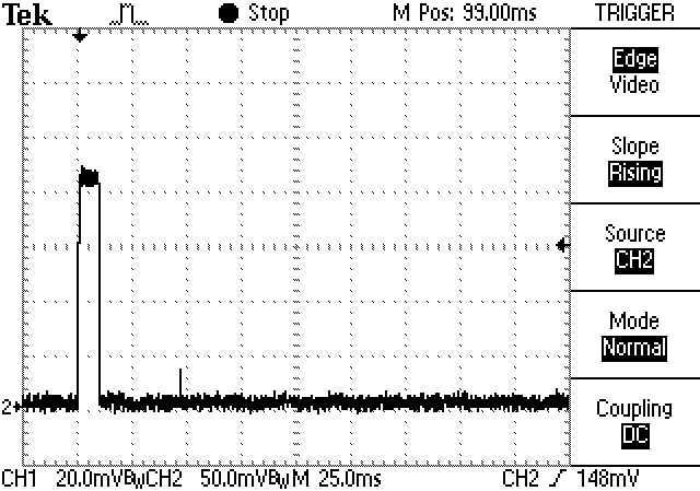
The minimal RTC-only sensor configuration reached a very brief battery current peak of ~2.7mA with no buffering cap, 1.5mA with 220µF and less than 1mA with 1000µF. The amount of voltage drop these currents create depend on the coin cells internal resistance but a typical unbuffered unit usually sees 15-30mV drops when the battery is new and this grows to ~200mV on old coin cells. The actual voltage drop also depends on time, with subsequent current spikes having more effect than the first as the internal reserve gets depleted. The following images display the voltage droop on a very old coin cell pulled from a logger that’s been in service since 2016 (@3µA average RTC backup)
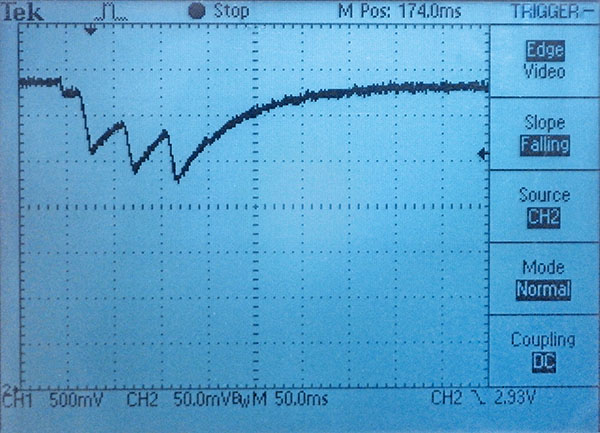
[Vertical: 50mv/div, Horizontal: now 50ms/div]
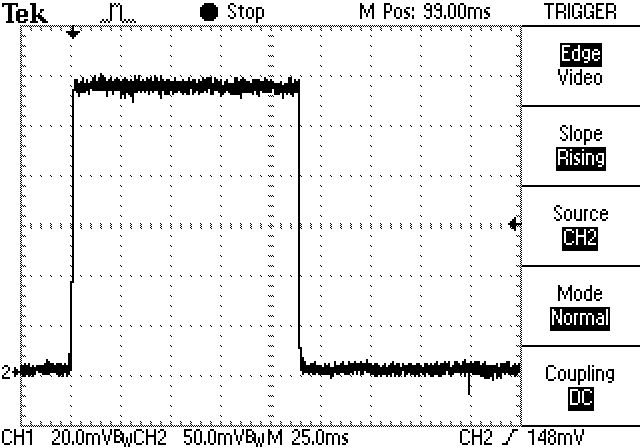
According to Nordic Semi: “A short pulse of peak current, say 7mA for 2 milliseconds followed by an idle period of 25ms is well within the limit of a Cr2032 battery to get the best possible use of its capacity.” After many tests like those above, our optimal ‘peak shaving’ solution is to run the processor at 8MHz, breaking up the execution time with multiple 15-30 millisecond POWER_DOWN sleeps before the CR2032 voltage has time to fall very far. (especially necessary if you start doing a lot of long integer or float calculations) This has the benefit that successive sensor readings start from similar initial voltages but those extra sleeps can easily stretch the duration of a logging event out toward 300 milliseconds – putting limits on the loggers maximum sampling rate:
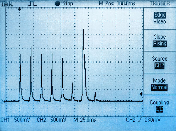
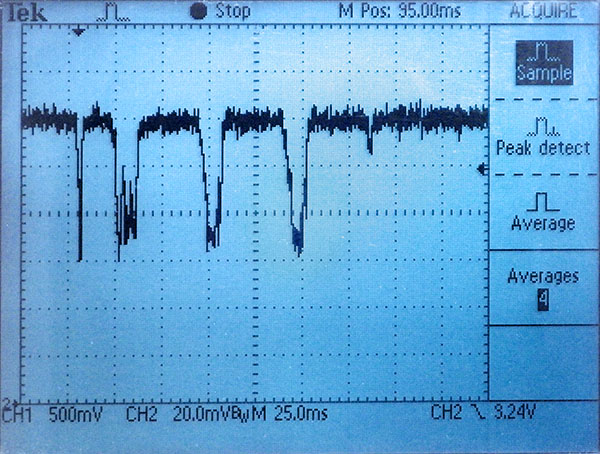
[CH2: H.scale: 25msec/div, V.scale 500µA/div converted via Current Ranger]

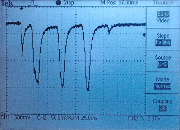
[CH2: V.scale 25mv/div, H.scale 25ms]
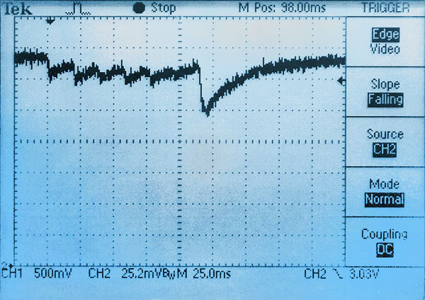
[CH2: V.scale 25mv/div, H.scale 25ms]
EEprom save events are typically around 3.5 mA for 6ms. Without a rail buffer a new coincell will fall about 100mv. With a 200µF rail buffering cap supplying the initial demand the peak current drawn from the coin cell is less than 1.5mA – which limits the overall voltage droop to less than 50mv. Even with very old batteries a typical EEsave event doesn’t usually drop the rail more than 150mv with a rail buffer cap, however the recovery time grows significantly with battery age – from less than 25 msec when new to more than 150 milliseconds for a full recovery. So old battery logging events look more like ‘blocks’ on the oscilloscope trace rather than the series of short spikes shown above.
Even with fierce memory limitations we only use the 328’s internal 1k EEprom for startup index values and text strings that get written while still tethered to the UART for power. EEprom.put starts blocking the CPU from the second 3.3msec / byte, and internal EEprom writing adds an additional 8mA to the ProMini’s normal 3mA draw. This exceeds the recommended 10mA max for a garden variety Cr2032. Multi-byte page writes aren’t possible so data saved into the 328p costs far more power than the same amount saved to an external EEprom. However it is worth noting that reading from the internal EEprom takes the same four clock ticks as an external with no power penalty, while PROGMEM takes three and RAM takes two clock cycles. So it doesn’t matter to your runtime power budget where you put constants or even large lookup tables.
A simple optimization we haven’t done with the code posted on GitHub is to buffer data into arrays first, and then send that accumulated data with larger wire library buffers. All AT-series EEproms can handle the 4k’s 32-byte page-write but the default wire library limits you to sending only 30 bytes per exchange because you lose two bytes for the register location. So to store sensor readings in 32-byte buffer arrays and transfer those you need to increase the wire library buffers to 34 bytes. This has to be done by manually editing the library files:
In wire.h (@ \Arduino\hardware\arduino\avr\libraries\Wire\src)
#define BUFFER_LENGTH 34
AND in twi.h (@ \Arduino\hardware\arduino\avr\libraries\Wire\src\utility)
#define TWI_BUFFER_LENGTH 34
That twi buffer gets replicated in three places so the wire library would then require proportionally more variable memory at compile time . With larger EEproms you could raise those buffers to 66 bytes for 64 data-byte transfers. It’s also worth mentioning that there are alternate I2C libraries out there (like the one from DSS) that don’t suffer from the default wire library limitations. AT series EEproms always erase & rewrite an entire page block no matter how many bytes are sent, so increasing the number of bytes sent per save event reduces wear and can save significant amounts of power. In my tests, newer larger EEproms tend to use about the same power as smaller older EEproms for identical save events because even though they are re-writing larger blocks, they do these internal operations much faster. So a ‘typical’ EEprom write event uses somewhere between 0.30 to 0.5 millamp-seconds of power no matter how many bytes you are saving. If your daily sleep-current burn is about 300milliampseconds, then it takes a few hundred of those EEprom save events to use the same amount of power. Increasing the transfer payload (with temporary accumulation arrays) from the I2C default of 16 bytes to 64 bytes cuts EEsave power use by 75%. That can extend the loggers operating life with short sampling intervals of 1-5 minutes, or where your sensors generate many bytes per record. Despite several technical references saying otherwise, I saw no significant difference in save duration or power (on the oscilloscope) with EEprom locations prewritten to all zeros or 0xFF before the data save events. One thing that does make an enormous difference is transferring blocks that exactly match the EEproms hardware page size – if you get the alignment perfect then EEproms can write the new information without all the preload & insertion operations you see when saving smaller amounts of data. This cuts both the time and the power for EEprom saving by 50% if you have enough memory for all the pre-buffering that requires.
Because of the code complexity we have not implemented array buffering in the current code-build so that the codebase is understandable for beginners. Every pass through the main loop saves data to the external EEprom and these loggers still have an excellent operating lifespan without it. For many EEprom types, when doing a partial write of fewer bytes than the hardware page size, the data in the rest of the page is refreshed along with the new data being written. This will force the entire page to endure a write cycle, so each memory location in the EEprom may actually get re-written [EEprom hardware page size / Bytes per Save ] times, which for the 4k would typically be 32/4 = 8 times per run. EEproms have a ‘soft’ wear limit of about 1,000,000 write cycles, so even in that worst-case scenario the logger could fill that chip 125,000 times before wearing the EEprom out. But buffering can make the eeprom last longer, or extend operating life in ways other than the battery power that’s saved.
FRAM takes about 1/50th as much power to write data compared to standard EEproms but those expensive chips often sleep around 30µA so they aren’t a great option for low-power systems like this logger unless you pin-power the chips so you can disconnect them during sleep. FRAM can endure more than 10 billion, 50 nano-second, write cycles, making it better suited for applications where rapid burst-sampling is required. The I2C bus is not really fast enough take advantage of FRAMs performance, but with the SD card removed from the logger the four SPI bus connections are now available. Once your code is optimized, the majority of the loggers runtime power is consumed by the 328p burning 3.5mA while it waits around for the relatively slow I2C bus transactions – even with the bus running at 400khz.
No matter what optimizations you make, battery life in the real world can also be shortened by thermal cycling, corrosion from moisture ingress, being chewed on by an angry dog, etc. And you still want the occasional high drain event to knock the passivation layer off the battery.
An important topic for a later post is data compression. Squashing low-rez readings into only one byte (like we do in the base code with the RTC temperature & battery voltage) is easy; especially if you subtract a fixed offset from the data first. But doing that trick with high range thermistor or lux readings is more of a challenge. Do you use ‘Frame of Reference’ deltas, or XOR’d mini-floats? We can’t afford much power for heavy calculations on a 328p so I’m still looking for an elegant solution.
Some Run Test Results
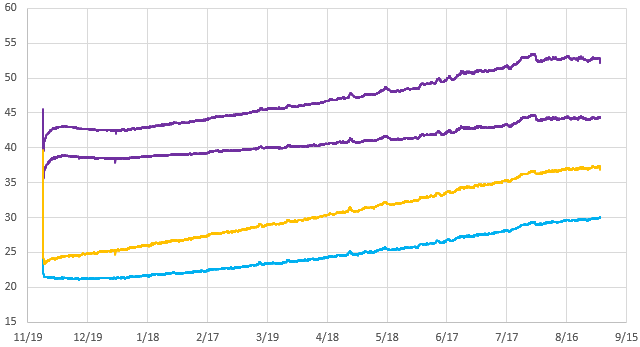
Since we covered adding BM & BH sensors, here’s a couple of burn-down curves for the two configurations described above. Both were saving 4 bytes of data per record every 30 minutes giving a runtime storage capacity of about 150 days. In this test, Battery was logged each time 16-byte buffer-arrays were written to a 32k EEprom. Both loggers have a measured sleep current of ~1.5µA and they were downloaded periodically. Although the curve spikes up after each download, these are runs used the same coin cell battery throughout:
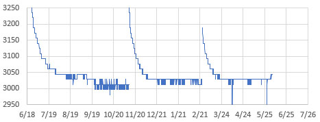

I ran these tests without a rail buffering cap, to see the ‘worst case’ lifespan. A pulse loaded Cr2032 has an internal resistance of ~20-30Ω for about 100 mAh of its operational life, so our 3.5mA EEprom writing event should only drop the rail 100mv with no rail buffer cap. But once the cell IR approaches 40Ω we will see drops reaching 200mv for those events. The CR2032’s shown above have plateaued near their nominal 3.0v, so we will see the rail droop to ~2800mv when the batteries age past the plateau. Again, our tests show that with a 220 µF rail capacitor those drops would be reduced to less than 50mv and with 1000µF the battery droop is virtually eliminated.
Note that the UART download process briefly restores the voltage because the 3.3v UART adapter drives a small reverse current through the cell. I think this removes some of the internal passivation layer, but that voltage restoration is short lived. On future tests I will enable both logCurrentBattery (after wake) and logLowestBattery (during EEwrite) to see if the delta between them matches the drops I see with a scope.
And here we compare our typical logging events to the current draw during a DS3231-SN RTC’s internal temperature conversion (with a 220µF/25v cap buffering the rail). The datasheet spec for the DS3231 temp conversion is 125-200ms at up to 600µA, but the units I tested draw half that at 3.3v. On all three of these images the horizontal division is 50 milliseconds, and vertical is 200µA via translation with a current ranger:

The datasheet spec for the DS3232-SN temp conversion is 125-200ms at up to 600µA, but the units I tested draw half that at 3.3v. The rail cap can’t protect the coin cell from the SN’s long duration load so temp conversions overlapping the EEprom save may be the trigger for most low voltage shutdowns during deployment. The best we can do to avoid these collisions is to check the DS3231 Status Register (0Fh) BSY bit2 and delay the save till the register clears. But even with that check, sooner or later, a temperature conversion will start in the middle of an EEprom save event. These ‘collisions’ may be more frequent with the -M variants of the chip which do temperature conversions every 10 seconds when powered by Vbat, although they only take 10msec for the conversion instead of 150msec for the -SN. Seeing those conversions on an oscilloscope is one way to verify which kind of RTC you’ve got with so many -SN modules out there today being relabelled -M chips:
Given that the average timekeeping current is the same for both chips, we try to use ±2ppm SN’s for longer deployments instead of the ±5ppm M’s. In real world terms ±1ppm is equivalent to about 2.6 seconds of drift per month, and that’s what we see on most -SN RTCs. I’ve also seen occasional comments in the forums of some DS3231M oscillators stopping spontaneously during field deployment. Note that on several of the RTC modules the SQW alarms continue to be asserted even after you disable them in the control register (by setting the alarm interrupt enable A1IE and A2IE bits to zero) and this draws 6-700uA continuously through the pullup on the module. The only way to be absolutely sure the RTC alarm will not fire after a logger shut-down is to turn off the RTC’s main oscillator. We do this in the codes shutdown function, because you can just reset the time via the start menu before the next run. When you remove the coincell, DS3231 register contents are lost – usually becoming zeros when power is restored although the datasheet says they are ‘undefined’ at powerup. The RTC oscillator is initially off until the first I2C access.
If your code hangs during execution, the processor will draw 3.5mA continuously until the battery drains and the logger goes into a BOD restart loop with the D13 red led flashing quickly. The logger will stay in that BOD loop from 4-12 hours until the battery falls below 2.7v without recovering. This has happened many times in development with no damage to the logger or to any data in the EEprom.
Most of the units I’ve tested trigger their BOD just below 2.77 volts. And 10 to 20 millivolts before the BOD triggers the internal voltage ref goes a bit wonky, reporting higher voltages than actual if you are using the 1.1vref trick to read the rail. The spring contact in the RTC module can be weak. That can trigger random shutdowns from large voltage drops so I usually slide a piece of heat-shrink behind it to strengthen contact with the flat surface of the coin cell. The rail capacitor protects the unit from most impacts which might briefly disconnect the spring contact under the coin cell. However hard knocks are a such common problem during fieldwork that we use a drop of hot glue to lock the RTC coin-cell in place before deployment. Normal operation will see 40-50mv drops during EEprom saves up to with 200µF rail buffers. If those events look unusually large or rail voltage recovery starts stretching to 100’s of milliseconds on the scope you probably have poor battery contact. Even with good contact, long duration loads can deplete the rail buffering cap so a 200µF reaches the same v-drop as a ‘naked’ battery after ~8-10msec, and 1000µF after ~15-20msec. In all cases, your first suspect when you see weird behavior is that the coin cell needs to be replaced.
Another thing to watch out for is that with sleep currents in the 1-2µA range, it takes a minute to run down even the little 4.7µF cap on the ProMini boards. If you have a larger capacitor buffering the rail the logger can run for more than 10 minutes after the battery is removed.
More Cr2023 Battery Testing

Ran a series of Cr2032 battery tests with these little loggers and was pleasantly surprised to find that even with the default BOD limiting us to the upper plateau of those lithium cells; we can still expect about two years of run time from most name brand batteries with a 200-400uF rail cap. Also keep in mind that all the units in the battery test had BOD’s below 2.8v – about 1 in 50 of the ProMini’s will have a high BOD at the maximum 2.9v value in the datasheet. It’s worth doing a burn test with the crappy HuaDao batteries to spot these high cutoff units more quickly so you can exclude them from deployment. We increased the sleep current for the accelerated test by leaving the LEDs on during sleep, but with a series of different resistors on the digital pins, this logger might be the cheapest way to simulate complex duty cycles for other devices.
Addendum: 2026-02
Recently retrieved a set of loggers (from a cave in the US) and the 14-month Cr2032 burn down curves from that set revealed an interesting fact about logger power consumption:
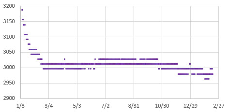
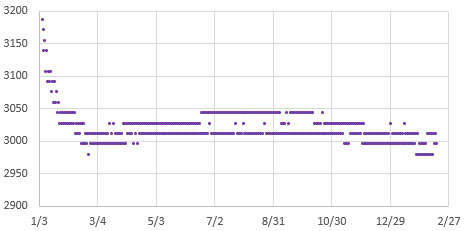
The points on the graphs above include both loaded and unloaded rail voltage readings. While the delta between the high & low reads is slightly larger for the -M logger with the higher baseload current, the overall run time between the two is quite similar because of the larger amount of power that the DS3231-SN uses during its 200msec temperature corrections. I would have incorrectly assumed the higher drain logger to have a significantly shorter runtime based on the constant sleep current baseline alone.
Addendum: Build video (w EEprom Upgrade)
We finally released a full build tutorial on YouTube – including how to upgrade the default 4k EEprom with two stacked 64k chips:
Addendum: (2023-12-01) The e360 EDU variant

Released the classroom version of this 2-module logger, with substantial code simplifications that make it easier to add new sensors and 2Module code build has been updated to match. This new variant has two breadboards supported on 3D printed rails so that sensor connections can quickly be changed from one lab activity to the next. The default code reads temperature via the RTC, and NTC thermistor, Light via an LDR and the Bh1750, and Pressure via a Bmp280. It also has support for a PIR sensor, and a mini-OLED display screen.
Macintosh users have been running into a very specific problem with this logger: their USB-c to USB-a adapter cables are smart devices with chips inside that will auto shut-down if you unplug them from the computer while they are connected to a battery powered logger. The VCC & GND header pins on the logger feed enough power/voltage back through the wires to make the chip in the dongle go into some kind of error state – after which it does not re-establish connection to the Mac properly until the adapter is completely de-powered. So you must unplug your loggers at the UART module to logger connection FIRST instead of simply pulling the whole string of still-attached devices out of the USBc port.
Last Word:
“If you need one, then you need two. And if you need two, you better have three.” The benefit of loggers this easy to produce is that you can dedicate one to each sensor, since the sensors often cost more than the rest of the unit combined. Then you can deploy duplicates to capture long time-series. This gives you redundancy in case of failure and makes it easier to spot when sensors start to drift. Deploying at least two loggers to every site also lets you use a trick from the old days when even the expensive commercial loggers didn’t have enough memory to capture an annual cycle: Set each logger to sample at twice the interval you actually want, and then stagger the readings (or set one of the logger clocks late by 1/2 of that interval). This way both loggers operate long enough to capture the entire dataset, and you can weave the readings from the two machines back together to get the higher sampling interval you originally wanted but did not have enough memory for. If one of the loggers fails you still get the complete season, but at the longer interval.
Dedicated loggers also provide the non-obvious benefit of reducing the potential for interference between sensors. Cross-talk is particularly common with water quality sensors because the water itself can form a circuit between them. It is nearly impossible to predict this kind of problem if all you did was benchtop calibration of the isolated sensors before your deployment. And even if your base code is robust, and you don’t have any weird ground-loops, it’s not unusual for sensor libraries to conflict with each other in a multi-sensor build.
Hopefully this new member of the Cave Pearl logger family goes some way toward explaining why we haven’t moved to a custom PCB: Using off-the-shelf modules that have global availability is critical to helping other researchers build on our work. And when you can build a logger in about 30 minutes, from the cheapest parts on eBay that still runs for a year on a coin cell – why bother? Bespoke PCBs are just another barrier to local fabrication, with potential for lengthy delays at customs to increase what may already be unpredictable shipping and import costs.
We’ve been having fun embedding these ‘ProMini-llennium Falcons’ into rain gauges and other equipment that predate the digital era. There’s a ton of old field kit like that collecting dust in the corner these days that’s still functional, but lacks any logging capability. Much of that older equipment was retired simply because the manufacturer stopped updating the software/drivers. While IOT visualization apps are all the rage in hobbyist electronics, they may end up creating similar dependencies that open source projects aiming for longevity should avoid. Not to mention the fact that those wireless packet transfers require a power budget orders of magnitude larger than the rest of the logger, while relying on back-end infrastructure that doesn’t exist in the parts of the world where more environmental monitoring is desperately needed.
References & Links:
Setting Accurate Logger time with a GPS
How to calibrate the NTC thermistors on this logger
Heliosoph: Arduino powered by a capacitor
Nick Gammon: Power Saving techniques for microprocessors
AVR4013: picoPower Basics for AVR Microcontrollers
Jack Ganssle: Hardware & Firmware Issues Using Ultra-Low Power MCUs
An Arduino-Based Platform for Monitoring Harsh Environments
Oregon Embedded Battery Life Calculator & our Cr2032 battery tests
A summary of Port/PIN mappings for Atmel based Arduinos
Waterproofing your Electronics Project
Calibrating a BH1750 Lux Sensor to Measure PAR
How to Normalize a Set of Pressure Sensors
WormFood’s AVR Baud Rate Calculator
ATmega328P Datasheet
AVR Application Notes

OK… wow. Um, you keep making me re-think, which is GREAT! Thank you!
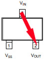
I admit one step I’ve not taken is stripping out the ProMini regulator and running unregulated (I’ve not even swapped to an external regulator just because I’m not sure which to do or how, and I haven’t needed it… YET). So that’s something I need to go back over everything and look at. I’ve also not taken the steps of disabling Vcc to the RTC because the soldering looked tricky… but here, with your trick of soldering a jumper from just over the diode in the battery charger circuit has me curious again for a different reason. That’s essentially connecting the RTC battery supply to the ProMini Vcc… but could you run this the other way? Remove the coin cell from the RTC (and frankly then desolder the coin cell holder off the board; it’s the biggest component and gets in the way), but do the same solder connection you do here to bring the ProMini’s Vcc rail over to the RTC, but coming in through the battery connection to keep the RTC running in low-power mode? Then my RTC and ProMini are all running off the main battery pack. Would that work? My goal here is to easily extend life by keeping the RTC in low-power mode and removing the coin cell battery holder entirely (I have enough room for batteries, but not that coin cell ironically. Also the wiring job between the RTC board and the ProMini is genius… and I wonder how much time you spend turning components around in your head. Same with the variety of sensor board / EEPROM board “co-wiring” solutions.
I take a different strategy than you do for “different records”; instead of writing them “forward from the front and backwards from the rear” as you do, I just freely mix them with a single byte (or if I was trying to save this much memory a single bit) in the front labeling which type of record it is to decompress, but that’s just a small difference. Since I’m still using the SD card I just pack all my data records as 30 byte records so I’m doing EEPORM page writes, and battery life rather than memory is my limiting factor, but I really love this. Also, your point about editing the wire.h library to expand the buffer just two bytes, so you can write the entire 32 bytes of a page, is something I really should have done earlier, and didn’t think about… I just hate editing library files like that because it tends to really break things for others going forward, but I might have to do it.
On data compression I need to think more… while I don’t need it to conserve total memory (SD cards are MASSIVE), I have been looking at it for compacting what I can fit in a single 30 byte record. Pressure sensors tend to be memory hogs (a single raw pressure or temperature reading takes up 4 bytes, and I’ve generally had two, so that measurement, uncompressed, chews up half the data record). Generally storing the simple differential is good enough but it’s another think I need to think about.
Dang, I just wrote my own blog post. Sorry 🙂
In our typical AA powered loggers, the usual RTC mod cuts the Vcc leg, and then cuts the connection from the positive coin cell terminal to the Vbat line and replaces it with a 1n1418.
Then the systems rail provides Vbat power whenever it’s higher than the coin cell-(minus the diode drop) which is most of the time with Lithium AA’s. That diode-OR setup works fine to power the RTC from the main system battery and I have not noticed any weird drift effects, etc. from the switching.
[edit: Now that I think about it…I should probably replace the diode on the RTC module with a lower vF Shottky to more preferentially supply from the larger lithium AA system batteries]
On this new ‘mini’ build I’ve also thought about replacing the coin cell battery holder with a 2x AAA holder & lithium cells, as that would easily tape down on that flat surface that’s left after removing the coin cell holder. But I’m working on another little trick there for posting soonish.
I’ve been trying to figure out a way to use Varints that works for larger thermal deltas that also doesn’t obfuscate the code to the point where it’s completely unreadable by students. But that method is really optimized for small numbers and even with the 104 caps the thermal deltas between readings of the NTC gives you four sig figs. I think I’ve an idea for a solution packing those readings into 16-byte arrays, but just adding more memory is so easy I’d really only be developing that for my own amusement.
Barometric pressure is easier to compress after you convert it to millibar. Then you can just subtract a fixed offset of the lowest expected reading at your latitude (about 980 where I live) and this leaves you with a normal range of about 30millibar. 2*(255) = 510 so if you can live with a resolution of only 0.2 millibar, then you can encode the rest of the pressure reading in one byte. This is essentially the same way we’ve encoded the battery readings to one byte only in that case I increased the spread with a 4x multiplier. But water level is more challenging due to the greater range. Perhaps you could generate periodic index/offsets and store those in the internal EEprom since you have loads of power on normal batteries?
And WRT wiring…yes, I probably spend far too much time on these little puzzles.
Hello, you can save on eeprom write times by using FRAM instead of flash/eeprom. There are modules on Adafruit : https://www.adafruit.com/product/1895
Basically, you can write byte by byte without penalty. The write time is shorter than the i2c transaction. Is simplifies a lot the code.
Last time I checked FRAM had sleep currents far too high for low power systems and those EEproms are so incredibly cheap: https://www.ebay.com/sch/i.html?_from=R40&_nkw=at24c512+50pcs&_sacat=0&LH_TitleDesc=0&_sop=15
We also use the EEprom writing load to stress the batteries, and that’s actually lead to another interesting observation: with older coin cells that have been sitting around for a while, we’re seeing cell voltages rise significantly after they have been running for a week or two with those 2-3mA pulse loads. I don’t have a ref handy but I recall reading somewhere that if you never bring a coin cell above single digit μA loads then a kind of passivation layer builds up inside which reduces the total amount of power you can get from them.
And there are lots of other power optimizations that could be done using more energy efficient CPUs & low power RTCs. But the point of this design was to make use of the parts already on a couple of cheap eBay modules so that non-engineering students could assemble it in one afternoon lab. I think we’ve achieved that nicely with this new build.
I solved the problem of sleep current by powering my fram with a digital output of the microcontroller (PIC24) making its sleep current probably in the nanoamp range (I didn’t have a microcurrent or a good microampmeter at the time, so I guessed it is that based on the time it worked). You also have to be careful not back powering the device from the i2c pins by disabling the i2c module in the uc. But it is effectively cheaper to use eeproms.
The Fujitsu FRAM in the Adafruit module doesn’t seem to have a sleep mode, just a standby mode, whereas Infineon/Cypress modules like FM24V10 have a 5uA sleep mode with operation down to 2v, which would be better than the 2.7v EEPROMS. The cost of the FRAM may outweigh the benefits though!
an easier way to disable the LEDs is to burn them out – I use a 4 x AA NiMH battery pack – touch the leads (5 volts) across the LED, a brief flash & a millisecond later the LED is no more – saves on desoldering
That’s one way to do it, but I think asking our students to try that method would be a recipe for even more dead Pro Mini boards in the lab…and they don’t really need help in that regard. 🙂
The Maxim datasheet https://datasheets.maximintegrated.com/en/ds/DS3231.pdf says the temperature accuracy is only +/-3 degrees. I don’t see any improved accuracy with S or SN packages. Are you are measuring temperature via the DS3231 or BMP280?
The ‘basic’ two part build reads the RTC record if you uncomment ‘RTC_ONLY’ in the initial program defines. For other sensors you have to connect & enable them at the start of the code and we included BMP280 support to show people the kind of changes you need to make to add other I2C sensors.
Yes the accuracy spec for the RTC temp is pretty rough, but when you actually test a large group of ‘-N’ and ‘-SN’ chips you find that most are only 0.25-0.5C away from actual. And that fixed offset is easy to correct over the range of temps seen by most student projects. BM sensor temps usually need exactly the same kind of correction because of self heating. The NTC requires a full calibration procedure against a reference sensor to derive the Steinhart–Hart constants – but then that’s another useful lab for the students work through.
I’m logging a mixed bunch of sensors at present – BME280, MCP9808, SCD30, various thermistors. The I2C ones all require periodic adjustments to the correction offsets over the months/ years for maximizing accuracy. So I spent a long time with NTC thermistors but they are even more troublesome when you are aiming/ desiring better than +/-0.2% accuracy ;-(
Yes. Things like ‘aging’ drift were far from my mind at the beginning of this project, but now, with up to a hundred loggers deployed at a given site, the data itself is telling us it’s an issue we can’t ignore. Our ratio-metric ICU method for reading thermistors is much better in that regard than traditional voltage dividers, but there are still several critical points. Sometimes there’s a known physical benchmark we can use for de-trending, but mostly we use a second calibration when the unit is retired (assuming it’s still operational…and didn’t get blown away by a Hurricane…) But that requires the drift to be both linear and unidirectional, when most of the stuff I’ve read says neither of those assumptions are true. I’ve also been playing with the idea of using the DS3231 temperature record for ‘on the fly’ drift corrections of the NTC data. That’s not perfect either, but at least it’s more characterized than cheap thermistors.
The problem is that if you assemble a build from high quality components with really good tolerances & drift specs – you’ve probably spent too much money on them to do the kind of exploratory tattle-tale deployments that make the research more fun. In our experience, deploying 10x as many cheap sensors is more likely to give you interesting data than best-guess deployments with a small number of expensive toys – even if the cheap sensor data needs more post processing. And our ‘obviously home-made’ loggers tend to be ignored in places where nicer looking commercial equipment would quickly grow legs and walk away on its own. . .
[Addendum: One thing that’s probably worth passing on is that the ageing effects we do see seem to be much more pronounced within the first year of a loggers lifespan. After that the whole system seems to ‘settle’ into much more constant (and slower) drift rates. So we usually run our loggers on a shelf somewhere from the moment they are made – even if they are intended for a deployment more than six months away. It’s probably not even worth calibrating them till they’ve had at least a two week short interval burn-in run]
So glad I’ve come across your blog. What an absolute mine of info. I’ve only read a small fraction of it so far, but hopeful it may give some tips for my own logging adventures.
How did you get the 328p down to 150nA when power down? The datasheet specifies the power down current is like 40uA
I think the 44uA in the datasheet is with both WDT (watch dog timer) & BOD (brown out detection) enabled. Rocket Scream’s Low Power library has an option to turn off the BOD in software and that’s required for sleeping down at 1uA. When you use this method the BOD is automatically re-enabled when the processor wakes so you still have protection from memory corruption. Occasionally you will get into the trap where the battery recovers but the start-up process draws enough current to pull the battery back down below the BOD cutoff, causing a restart-shutdown loop until the battery depletes. Fortunately with coin cells that limbo state doesn’t usually last long.
You can write the data directly to the atmega328p flash using a modified bootloader. You don’t need a RTC either: if you de-solder the high speed crystal (with a 25$ hot air station), you can replace it with a 32khz crystal! You can then run your own RTC using asynchronous timer2 and powersave sleep mode (leaving timer2 on while sleeping). It sleeps at less than 1uA while keeping accurate track of time. You can then run on your CR2032 for much longer, cause you use less current and you don’t have the 2.7V limit.
Our whole aim with this 2-Part build was to avoid complications like bootloader mods so that the logger is easier for beginner level students to understand & work with. And with a raw crystal I’d be worried about thermal effects over the kind of time periods that loggers usually get deployed – correcting these drift errors are really what modern RTC’s do and there are several that mange it in the nA range. But you won’t find those really good RTC’s on cheep eBay modules.
Pingback: Powering an Arduino Pro Mini logger for one year on a coin cell « Adafruit Industries – Makers, hackers, artists, designers and engineers!
Wondering if it is possible to modify this to see a change in state from a float switch or ultrasonic sensor, interested in building a data logger that could be positioned in tidal creek to log on off times of a switch rising to a set level and then comparing to tide chart heights to determine access times by boat to shallow areas
I would like to build this as a low-cost data logger build tough to handle saltwater conditions,
This is easily done with the same circuit we use on our tipping bucket rain gauges which puts about 5msec of debounce into the event. ( See: Building an Arduino Weather station https://thecavepearlproject.org/2015/06/15/developing-an-arduino-based-weather-station/ ).
The trick is getting two interrups to ‘interweave’ properly and I do that with a sub-loop at the end of the main loop, which only responds to the interrupt from the reed switch. Take a look at our old drip sensor code on github to see how we do that:
https://github.com/EKMallon/The_Cave_Pearl_Project_OLD_codebuilds/blob/master/_20141002_DripSensors_WithPowerControl/_20141002_DripSensors_WithPowerControl.ino
This uses interrups on D2 from the RTC, and D3 from the accelerometer to wake the system with sleepNwait4AccInterrupt. The ISR’s set flags, and only when the D2 RTC alarm flag is set does the processor break out of the while(clockInterrupt == false){ loop at the end of the main loop.