With the DS18B20 temperature sensors in place, it was time to add the ‘depth’ part of the standard CDT suite. After reading an introduction to the Fundamentals of Pressure Sensor Technology, I understood that most of the pressure sensors out there would not be suitable for depth sensing because they are gauge pressure sensors, which need to have a “low side” port vented to atmosphere (even if the port for this is hidden from view).
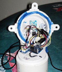
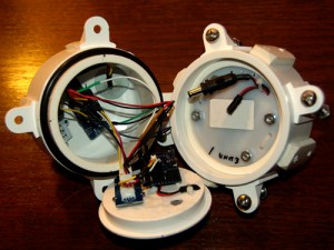
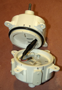
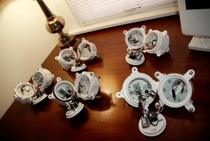
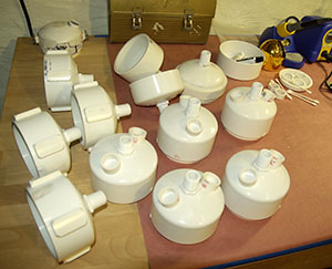
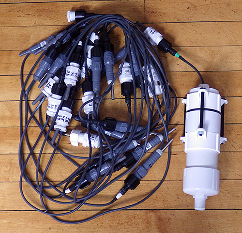
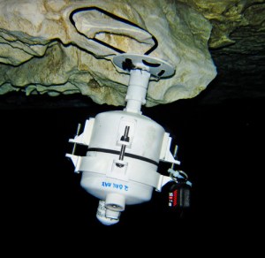
This is one of our earliest pressure loggers with a 3″ pvc housing. We now use 2″ PVC pipes (shown at the end of this post) which are much easier to to construct. For an exploded view of the new housing see the appendix at the end of the article in Sensors.
I needed an “absolute” pressure transducer, that has had it’s low side port sealed to a vacuum. I found a plethora of great altimiter projects in the rocketry & octocopter world, (with Kalman filtering!) but far fewer people doing underwater implementations in caves. But there are a few DIY dive computer projects out there, at various stages of completion, that use versions of the MS5541C & MS5803 pressure sensors from Measurement Specialties, or the MPX5700 series from Freescale. Victor Konshin had published some code support for the MS5803 sensors on Github, but his .cpp was accessing them in SPI mode, and I really wanted to stick with an I2C implementation as part of my quest for a system with truly interchangeable sensors. That lead me to the Open ROV project were they had integrated the 14 bar version of the MS5803 into their IMU sensor package. And they were using an I2C implementation. Excellent! I ordered a couple of 2 bar, and 5 bar sensors from Servoflo ($25 each +shipping..ouch!) , and a set of SMT breakout boards from Adafruit. A little bit of kitchen skillet reflow, and things were progressing well. (note: I mount these sensors now by hand, which is faster after you get the hang of it it)

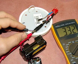
My first “real” hack on the project so far. (Note: This material was posted in early 2014 , and the only reason I did this hack was that at the time I was running the Tinyduino stack directly from an unregulated 4.5 battery. On my more recent loggers, built with regulated 3.3v promini style boards, I can just use the Vcc line to power the MS5803 sensors, without all this bother…)
But as I dug further into the MS5803 spec sheets I discovered a slight complication. These sensors required a supply voltage between 1.8 – 3.6 V, and my unregulated Tinyduino stack, running on 3 AA’s, was swinging from 4.7 down to 2.8v. I was going to need some sort of voltage regulator to bring the logic levels into a range that the senor’s could tolerate, with all the attendant power losses that implied… And then it dawned on me that this same problem must exist for the other I2c sensors already available on the Tinyduino platform. So perhaps I might be able to hack into those board connections and drive my pressure sensor? (instead of burning away months worth of power regulating the entire system) The Tiny Ambient Light Sensor shield carried the TAOS TSL2572 which had nearly identical voltage and power requirements to my MS5803.
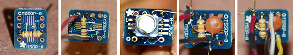
I used JB weld to provide support for those delicate solder connections.
So their voltage regulator, and level shifter, could do all the work for me if I could lift those traces. But that was going to be the most delicate soldering work I have ever attempted. And I won’t pull your leg, it was grim, very grim indeed. Excess heat from the iron conducted across the board and melted the previous joints with each additional wire I added. So while the sensors themselves came off easily with an drywall knife, it took two hours (of colorful language…) to lift the traces out to separate jumper wires. I immediately slapped on a generous amount of JB weld, because the connections were so incredibly fragile. I produced a couple of these breakouts, because I have other sensors to test, and I face this same logic level/voltage problem on the I2C lines every time I power the unregulated Tiny duino’s from a computer USB port.
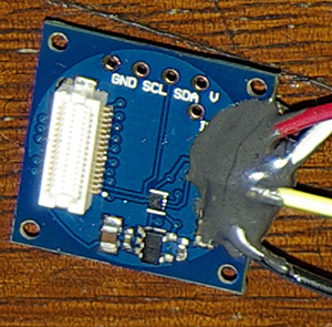
With a connection to the mcu sorted, it was time to look at the pressure sensor itself. Because I wanted the sensor potted as cleanly as possible, I put the resistor, capacitor, and connections below the breakout board when I translated the suggested connection pattern from the datasheets to this diagram:

This is viewed from above, with only one jumper above the plane of the SOIC-8 breakout. I used a 100nF (104) decoupling cap. The PS pin (protocol select) jumps to VDD setting I2C mode, and a 10K pulls CSB high, to set the address to 0x76. Connecting CSB to GND would set the I2C address to 0x77 so you can potentially connect two MS5803 pressure sensors to the same bus.
And fortunately the solder connections are the same for the 5 bar, and the 2 bar versions:
I’ve learned not waste time making the solder joints “look pretty”. If they work, I just leave them.
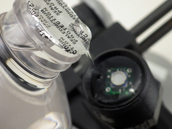
After testing that the sensors were actually working, I potted them into the housings using JB plastic weld putty, and Loctite E30CL:

The Loctite applicator gun is expensive, but it gives you the ability to bring the epoxy right to the edge of the metal ring on the pressure sensor.
So that left only the script. The clearly written code by by Walt Holm (on the Open ROV github) was designed around the 14 bar sensor; great for a DIY submersible, but not quite sensitive enough to detecting how a rainfall event affects an aquifer. So I spent some time modifying their calculations to match those on the 2 Bar MS5803-02 datasheet :
// Calculate the actual Temperature (first-order computation)
TempDifference = (float)(AdcTemperature – ((long)CalConstant[5] * pow(2, 8)));
Temperature = (TempDifference * (float)CalConstant[6])/ pow(2, 23);
Temperature = Temperature + 2000; // temp in hundredths of a degree C
// Calculate the second-order offsets
if (Temperature < 2000.0) // Is temperature below or above 20.00 deg C?
{T2 = 3 * pow(TempDifference, 2) / pow(2, 31);
Off2 = 61 * pow((Temperature – 2000.0), 2);
Off2 = Off2 / pow(2, 4);
Sens2 = 2 * pow((Temperature – 2000.0), 2);}
else
{T2 = 0;
Off2 = 0;
Sens2 = 0;}
// Calculate the pressure parameters for 2 bar sensor
Offset = (float)CalConstant[2] * pow(2,17);
Offset = Offset + ((float)CalConstant[4] * TempDifference / pow(2, 6));
Sensitivity = (float)CalConstant[1] * pow(2, 16);
Sensitivity = Sensitivity + ((float)CalConstant[3] * TempDifference / pow(2, 7));
// Add second-order corrections
Offset = Offset – Off2;
Sensitivity = Sensitivity – Sens2;
// Calculate absolute pressure in bars
Pressure = (float)AdcPressure * Sensitivity / pow(2, 21);
Pressure = Pressure – Offset;
Pressure = Pressure / pow(2, 15);
Pressure = Pressure / 100; // Set output to millibars
The nice thing about this sensor is that it also delivers a high resolution temperature signal, so my stationary pressure logger does not need a second sensor for that.
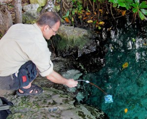
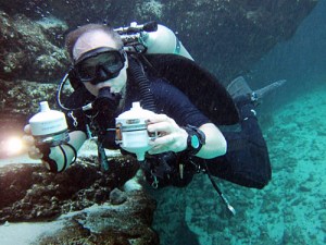
A Reefnet Census Ultra is co-deployed with my pressure sensor to ground truth this initial run.
So that’s it, the unit went under water on March 22, 2014, and the current plan is to leave it there for about 4 months. This kind of long duration submersion is probably way out of spec for the epoxy, and for the pressure sensors flexible gel cap. But at least we potted the sensor board with a clear epoxy, so it should be relatively easy to see how well everything stands up to the constant exposure. (I do wonder if I should have put a layer of silicone over top of the sensor like some of the dive computer manufacturers)
Addendum 2014-03-30
I keep finding rumors of a really cheap “uncompensated” pressure sensor out there on the net for about 5 bucks: the HopeRF HSF700-TQ. But I have yet to find any for sale in quantities less than 1000 units. If anyone finds a source for a small number of these guys, please post a link in the comments, and I will test them out. The ten dollar MS5805-02BA might also be pressed into service for shallow deployments using its extended range, if one can seal the open port well enough with silicone. And if all of these fail due to the long duration of exposure, I will go up market to industrial sensors isolated in silicon oil , like the 86bsd, but I am sure they will cost an arm and a leg.
Addendum 2014-04-15
Looks like Luke Miller has found the the float values used in the calculations from the ROV code generates significant errors. He has corrected them to integers and posted code on his github. Unfortunately one of the glitches he found was at 22.5°C, right around the temperature of the water my units are deployed in. I won’t know for some months how this affects my prototypes. With my so many sensors hanging off of my units, I don’t actually have enough free ram left for his “long int” calculations, so I am just logging the raw data for processing later.
Addendum 2014-09-10
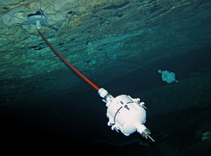
The unit in the picture above survived till we replaced that sensor with a 5-Bar unit on Aug 25th. That’s five months under water for a sensor that is only rated in the spec sheets for a couple of hours of submersion. I still have to pull the barometric signal out of the combined” readings, but on first bounce, the data looks good (mirroring the record from the Reefnet Sensus Ultra) Since the 2-Bar sensor was still running, it was redeployed in Rio Secreto Cave (above the water table) on 2014-09-03. It will be interesting to see just how long one of these little sensors will last.
Addendum 2014-12-18
The 2Bar unit (in the photo above) delivered several months of beautiful barometric data from it’s “dry” cave deployment, and was redeployed for a second underwater stint in Dec 2014. The 5Bar unit survived 4 months of salt water exposure, but we only got a month of data from it because an epoxy failure on the temperature sensor drained the batteries instantly. After a makeshift repair in the field, it has now been re-deployed as a surface pressure unit. The good news is that we had the 5Bar sensor under a layer of QSil 216 Clear Liquid Silicone, and the pressure readings look normal compared to the naked 2bar sensor it replaced. So this will become part of my standard treatment for underwater pressure sensors to give them an extra layer of protection.
[NOTE: DO NOT COAT YOUR SENSORS LIKE THIS! – this silicone rubber coating failed dramatically later – it was only the stable thermal environment of the caves that made it seem like it was working initially and the silicone also seemed to change its physical volume with long exposure to salt water. I’m leaving the original material in place on this blog as it’s an honest record of the kinds of mistakes I worked through during this projects development.]
Addendum 2015-01-16

I know the MCP9808 is a little redundant here, but at $5 each, it’s nice to reach ±0.25ºC accuracy. The MS5803’s are only rated to ±2.5ºC, and you can really see that in the data when you compare the two. The low profile 5050 LED still has good visibility with a 50K Ω limiter on the common ground line. Test your sensors & led well before you pour the epoxy! (Note: the 9808 temp sensor & LED pictured here failed after about 8 months at 10m. I suspect this was due to the epoxy flexing under pressure at depth because of the large exposed surface area. The MS5803 was still working fine.)
Just thought I would post an update on how I am mounting the current crop of pressure sensors. My new underwater housing design had less surface area so I combined the pressure sensor, the temperature sensor, and the indicator LED into a single well which gives me the flexibility to use larger breakout boards. That’s allot of surface area to expose at depth, so I expect there will some flexing forces. At this point I have enough confidence in the Loctite ECL30 to pot everything together, even though my open ocean tests have seen significant yellowing. The bio-fouling is pretty intense out there, so it could just be critters chewing on the epoxy compound. Hopefully a surface layer of Qsil will protect this new batch from that fate.
Addendum 2015-03-02
Just put a 4-5mm coating of Qsil over a few MS5803’s in this new single-ring mount, and on the bench the coating seems to reduce the pressure reading by between 10-50 mbar, as compared to the readings I get from the sensors that are uncoated. Given that these sensors are ±2.5% to begin with, the worst ones have about doubled their error. I don’t know if this will be constant through the depth range, or if the offset will change with temperature, but if it means that I can rely on the sensor operating for one full year under water, I will live with it.
Addendum 2015-04-06 : Qsil Silicone Coating idea FAILS
Just returned from a bit of fieldwork where we had re-purposed a pressure sensor from underwater work to the surface. That sensor had Qsil silicone on it, and while it delivered a beautiful record in the the flooded caves, where temperatures vary by less than a degree, it went completely bananas out in the tropical sun where temps varied by 20°C or more per day. I suspect that the silicone was expanding and contracting with temperature, and this caused physical pressure on the sensor that completely swamped the barometric pressure signal.
Addendum 2016-02-01
Use the smallest with zip tie you can find.
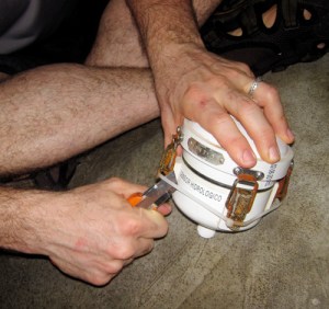
Since these are SMD sensors, mounting them can be a bit of a pain so I though would add a few comments about getting them ready. I find that holding the sensor in place with a zip tie around the SOIC-8 breakout makes a huge difference. Also, I find it easier to use the standard sharp tip on my Hakko, rather than a fine point which never seem to transfer the heat as well.
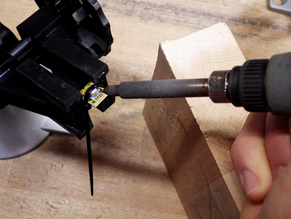
I also use a wood block to steady my hand during the smd scale soldering.
I plant the point of the iron into the small vertical grooves on the side of the sensor. I then apply a tiny bead of solder to the tip of the iron, which usually ends up sitting on top, then I roll the iron between my fingers to bring this the bead around to make contact with the pads on the board. So far this technique has been working fairly well, and though the sensors do get pretty warm they have all survived so far. If you get bridging, you can usually flick away the excess solder if you hold the sensor so that the bridged pads are pointing downwards when you re-heat them.
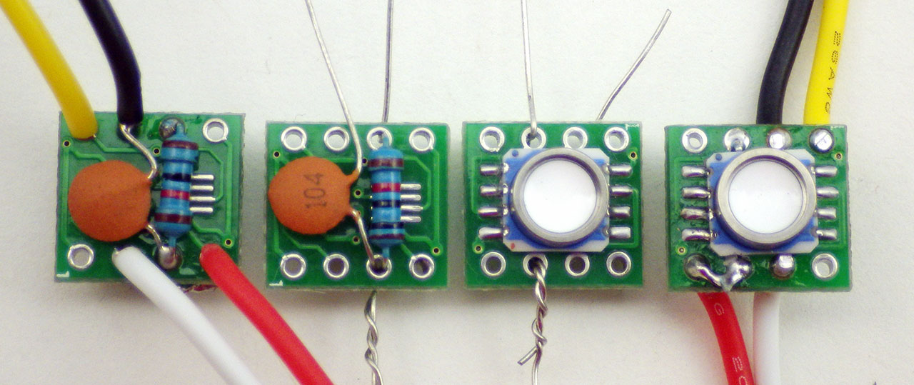
After mounting the sensor to the breakout board, I think of the rest of the job in two stages: step one is the innermost pair (which are flipped horizontally relative to each other) , and step two by the outermost pair where I attach the incoming I2C wires. Here SCL is yellow, and SDA is white. In this configuration CSB is pulled up by that resistor, giving you an I2C address of 0x76. If you wanted a 0x77 buss address, you would leave out the resistor and attach the now empty hole immediately beside the black wire to that GND line.
Sometimes you need to heat all of the contacts on the side of the sensor at the same time with the flat of the iron to re-flow any bridges that have occurred underneath the sensor itself. If your sensor does not work, or gives you the wrong I2C address, its probably because of this hidden bridging problem.
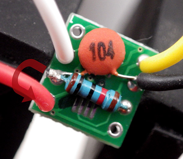
Adafruit still makes the nicest boards to work with, but the cheap eBay SOIC8 breakouts (like the one pictured above) have also worked fine and they let me mount the board in smaller epoxy wells. Leave the shared leg of the pullup resistor/capacitor long enough to jump over to Vcc on the top side of the board .
Addendum 2016-03-08
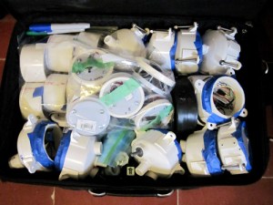
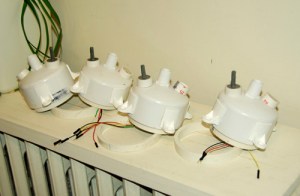
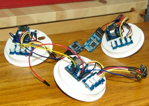
Have the next generation of pressure sensors running burn tests to see what offsets have been induced by contraction of the epoxy. I’ve been experimenting with different mounting styles, to see if that plays a part too:
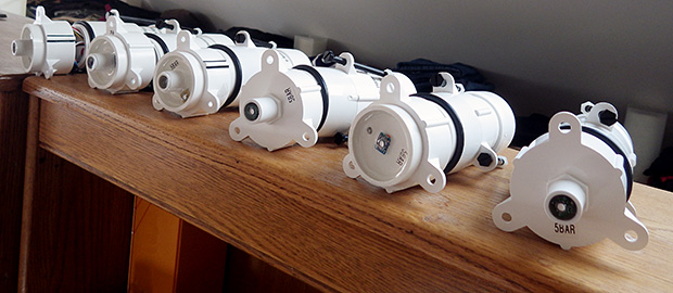
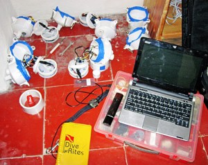
The housings are left open during the bookshelf runs as it takes a couple of weeks for the pvc solvent to completely clear out, and who knows what effect that would have on the circuits. (Note: for more details on how I built these loggers and housings, you can download the paper from Sensors )
The MS5803’s auto-sleep brilliantly, so several of these loggers make it down to ~0.085 mA between readings, and most of that is due to the SD card. I’m still using E-30Cl, but wondering if other potting compounds might be better? There just isn’t much selection out there in if you can only buy small quantities. The E30 flexed enough on deeper deployments that the bowing eventually killed off the 5050 LEDs. ( standard 5mm encapsulated LEDs are a better choice ) And I saw some suspicious trends in the temp readings from the MCP9808 under that epoxy too…
Addendum 2016-03-09
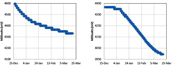
Just a quick snapshot from the run test pictured above:
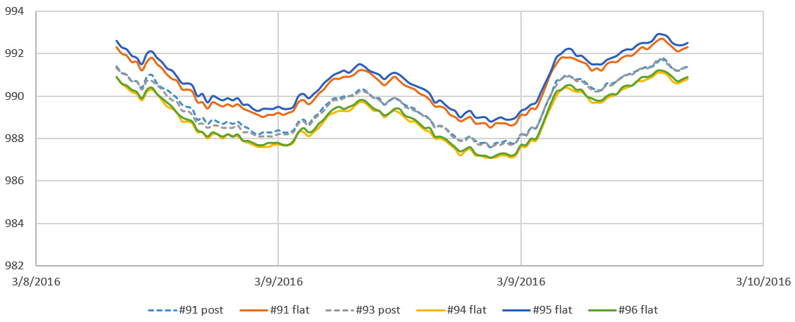
These are just quick first-order calculations (in a room above 20°C). Apparently no effect from the different mounting configurations, but by comparison to the local weather.gov records, the whole set is reading low by about 20 mbar. This agrees with the offsets I’ve seen in other MS5803 builds, but I am kicking myself now for not testing this set of sensors more thoroughly before I mounted them. Will do that properly on the next batch.
Addendum 2016-09-22
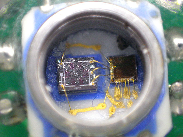
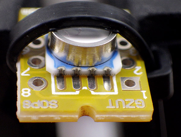
The inside of an MS5803, after the white silicone gel covering the sensor was knocked off by accident.
You can change the I2C address on these sensors to either 0x76 or 0x77 by connecting the CSB pin to either VDD or GND. This lets you connect two pressure sensors to the same logger, and I’ve been having great success putting that second sensor on cables as long as 25 m. This opens up a host of possibilities for environmental monitoring especially for things like tide-gauge applications, where the logger can be kept above water for easier servicing. It’s worth noting that on a couple of deployments, we’ve seen data loss because the senor spontaneously switched it’s bus address AFTER several months of running while potted in epoxy. My still unproven assumption is that somehow moisture penetrated the epoxy, and either oxidized a weak solder joint, or provided some other current path that caused the sensor to switch over.
Addendum 2017-04-30

Hypersaline environments will chew through the white cap in about 3 months.
Given what a pain these little sensors are to mount, it’s been interesting to see the price of these pressure sensor breakout modules falling over time. This spring the 1 & 14 bar versions fell below $24 on eBay. Of course they could be fake or defective in some way, but I’m probably going to order a few GY-MS5803’s to see how they compare to the real thing.
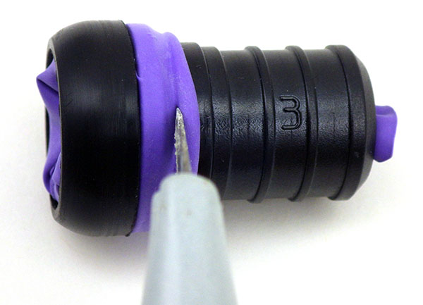
Addendum 2020-02-29: Mounting Pressure Sensors under Oil
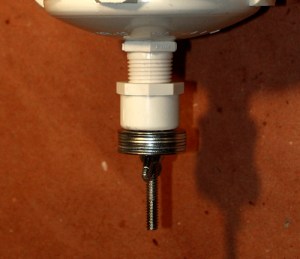
When exposed to freshwater environments & deployed at less than 10m depth, a typical MS5803 gives us 2-3 years of data before it expires. However we often do deployments in ocean estuaries where wave energy & high salt concentrations shorten the operating life to a year or less. So now we mount them on replaceable dongles, so that it’s easy to replace an expired sensor in the field. I described that sensor mounting system in the 2017 build videos:
Media isolated pressure sensors are common in the industrial market, but they are quite expensive. So we’ve also used these dongles to protect our pressure sensors under a layer of oil. I’ve seen this done by the ROV crowd using comercial isolation membranes, or IV drip bags as flexible bladders, but like most of our approaches, the goal here was to develop a method I could retro-fit to the units already in the field, and repair using materials from the local grocery store:
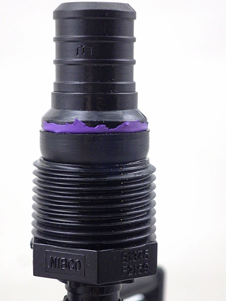
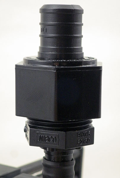
 The sensor is already potted into a NIBCO 1/2″ x 3/4″ Male Pex Adapter, to which we will mate a NIBCO 3/4″ Female Swivel Adapter. |
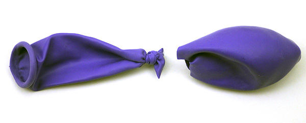 Since the balloon in this case is too large, I simply tie & cut it down to size. You can also cut your membrane from gloves or use small-size nitrile finger cots |
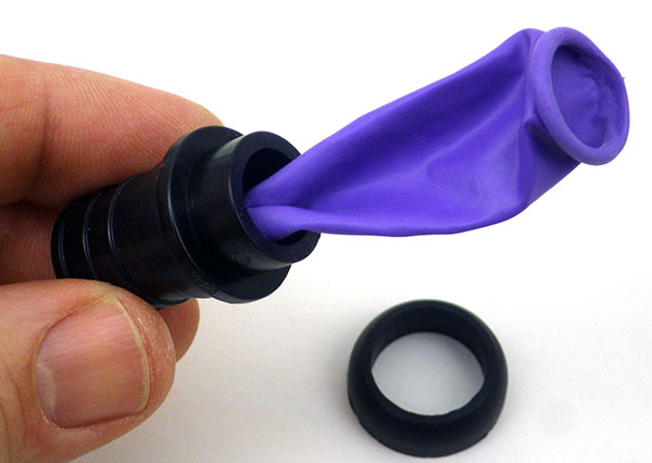 Remove the O-ring from the swivel adapter stem and insert the ‘neck’ of the balloon. |
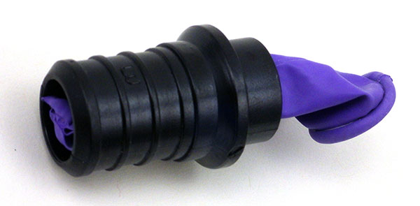 Pull the balloon through till the knot-end becomes visible. |
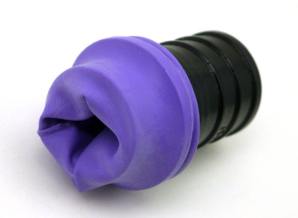 Pull the balloon over the rim on the other side of the pex adapter. |
 Place the O-ring over the balloon, and cut away the rolled end material. |
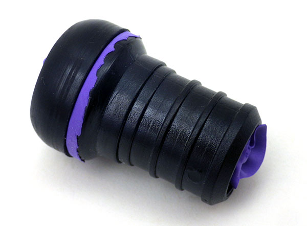 Now the threaded swivel ring will not bind on rubber when it gets tightened. Note the knot is just visible at the stem |
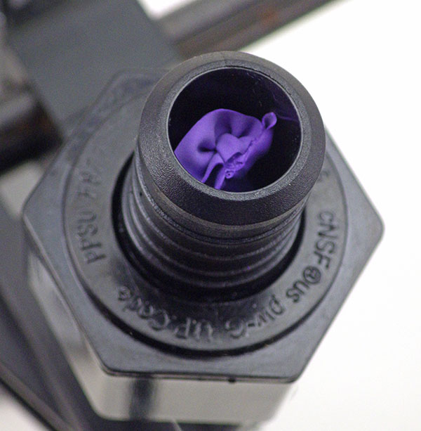
 Fill the mounted sensor ‘cup’ with silicone oil or mineral oil. You could also use lubricants produced by o-ring manufacturers that do not degrade rubbers over time.
|
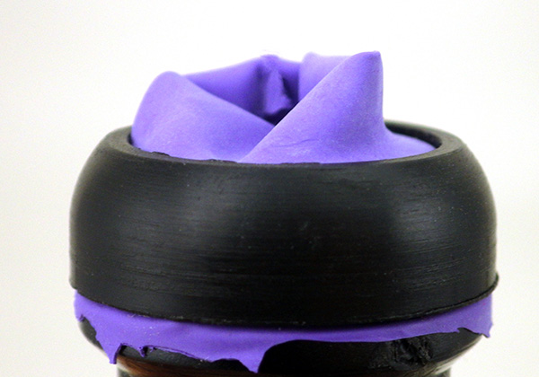 Gently push the balloon back out of the stem so that there is extra material in direct contact with oil. You don’t want the membrane stretched tight when you bring the parts together. |
 Then place the swivel stem on the sensor cup with enough extra membrate so it can moves freely inside the protective stem. |
 . . . and tighten down with the threaded ring to create a water-tight seal.
|
 After assembly the membrane material should be quite loose to accommodate pressure changes & any thermal expansion of the oil. |
Small trapped air bubbles can cause serious problems in dynamic hydraulic systems, but I don’t think the volume of air in the balloon matters as much when you are only taking one reading every 5-15 minutes. If you do this oil mount with other common pressure sensors like the BMP280 then you are pretty much guaranteed to have some kind bubble inside the sensor can, but so far I have not seen any delta when compared to ‘naked’ sensors of the same type on parallel test runs. It’s also worth noting that depending on the brand, finger cots can be quite thin, and in those cases I sometimes use two layers for a more robust membrane. Put a drop or two of oil between the joined surfaces of the membranes with a cotton swab to prevent binding – they must slide freely against each other and inside the pex stem.
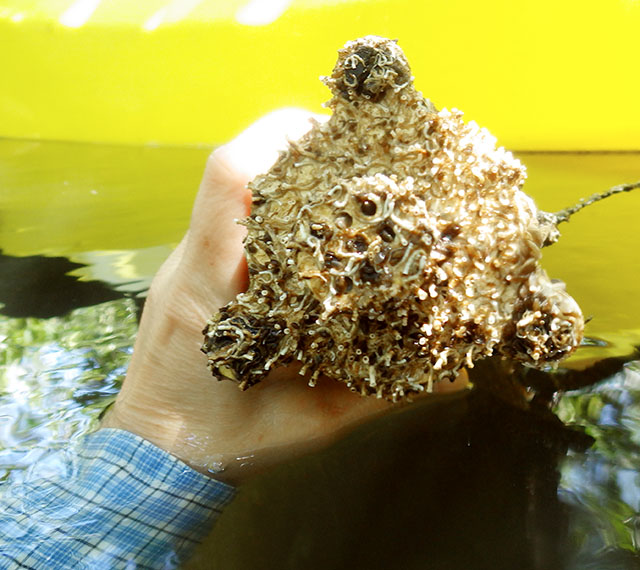
Yes, there is a pressure sensor buried in there! We got data for ~3.5 months before the worms covered it completely. In these conditions a larger IV bag is a better choice than the small oil reservoir I’ve described above. Simply attach that flexible oil-filled bladder directly to the stem of a 1/2″pex x 3/4″swivel connector with a crimp ring.
It’s also worth adding a comment here on the quality of the oil that you use. For example, silicone oil can be used on o-rings, and sources like Parker O-ring handbook describe this as “safe all rubber polymers”. But it’s often hard to find pure silicone oil and hardware store versions often use a carrier or thinner (like kerosene) that will damage or even outright dissolve rubbers on contact. And although we’ve used the mineral oil/balloon combination for short periods, nitrile is a better option in terms of longevity. With nitrile’s lower flexibility, you have to be careful when fitting cots over the o-ring end of the connector tube because it leaves leaky folds if theres too much extra material, or tears easily if it’s too small. In all cases the flexible material should fit into the stems 3/4 inch diameter without introducing any tension in the membrane when you assemble the connector parts. It must be free to move back & forth in response to external pressure changes.

Our latest housing design with direct connections to make sensor replacement easier
Also note if you have to build one of the larger white PVC sensor cups shown in the video (because your sensor is mounted on a large breakout board) then I’ve found that clear silica gel beads make a reasonable filler material under the breakout board BEFORE you pour the potting epoxy into the sensor well. This reduces the amount epoxy needed so that there is less volume contraction when it cures, but a low viscosity epoxy like E30CL still flows well enough around the beads and allows the air bubbles to escape. With wide diameter sensor cups, you will probably have to switch over to something like a polyurethane condom as the barrier membrane.
Addendum 2021-10-12:
Just an update on how I now prepare these raw sensors: 30 AWG breakout wires attach directly to the MS5803 pressure sensor with CSB to GND (setting sensor address to 0x77) & PS bridged to Vcc (setting I2C mode) via the 104 ceramic decoupling capacitor legs. In these photos SDA is white & SCL is yellow.
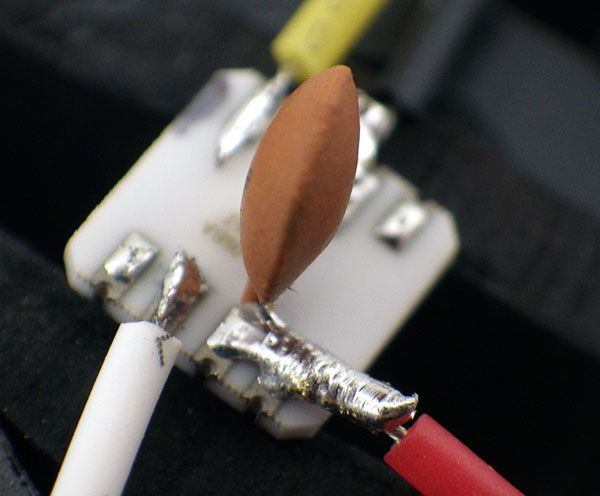
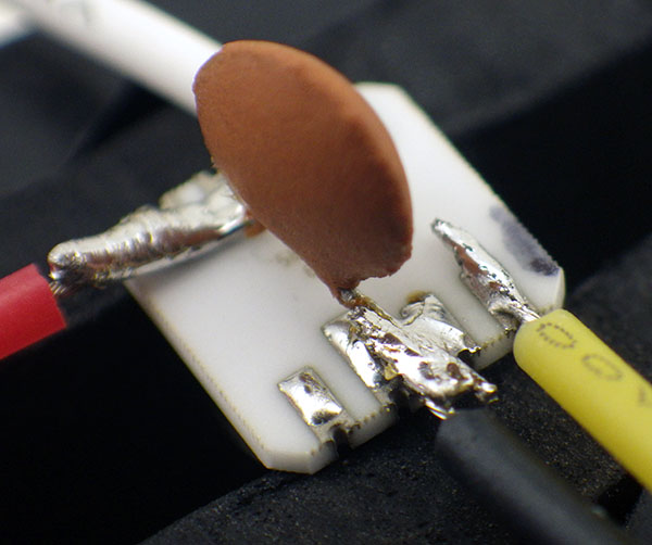
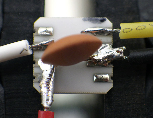
The wire connections are then embedded in epoxy inside our standard sensor dongles.
Addendum 2024-09-15:
We posted a new tutorial on: How to Normalize a Set of Pressure Sensors. There are always offsets between pressure sensors from different manufacturers, and normalization lets you use them together in the same sensor array.