
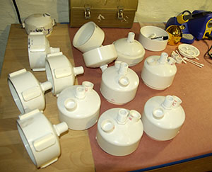
New housings in production. The sensor wells on top will be filled with epoxy to seal the hull. Note: some of these housings have unnecessary “chunks” of PVC on the outside, as I made them for latch clamps which I am no longer using in the design.
I haven’t had time to post to the blog lately, as I am now in full-on production mode: trying to get five full units running for deployment next week. Between all the cutting and sanding of the new underwater housings, I have been investigating sensors, and thinking about how to make the entire unit modular enough to allow quick field repairs. The I2C bus architecture becomes very attractive here, because so many sensors are available for it, and I found a nifty I2C hub from Seed studios, which gives me a standard plug for connectivity. But most of the sensors I found want a steady 3.3 volt supply, and that is not available on the Tiny Duino (the lack of a 3.3v rail is a weakness of the platform but I was the one who wanted to run with no voltage regulator in the first place..) So I started designing a power supply module around a NCP1402-3.3V Step-Up Breakout from Sparkfun. I knew this was going to waste 25% of my power for this deployment, but I figured I could use lithium AA’s to make up for the loss, and look around for a more efficient voltage regulator later.

It seemed to be working fine…
Well, a frustrating day or two later and I still had no joy from the 3.3v regulator. I don’t know if it was an inrush current brownout, or transient spikes, or output ripple…but for some reason the tiny stack simply will not run from this regulator – all I get is one little pip out of the on-board led and that’s it. Grrr! There goes about half of sensors I planned to use with the nice I2C breakout boards I had just purchased, unless I can somehow power the sensors “separately” from the main mcu stack. (And there is no guarantee I won’t have the same kind of gremlins pestering me there…)
Time to make lemonade: I had a few DS18B20 one wire temperature sensors, and they are not too choosy about input voltage, so I figured I would give them a try, while just running the Tiny’s from unregulated AA’s (…again). DS18B20’s are common as dirt, and almost as cheap, and there are libraries for them everywhere. So it should not take long to get them going…right?
Well what I thought was going to take me 30 minutes has actually taken me a day of digging to sort out, so I am posting the result here, to hopefully save someone else the trouble. The standard approach is to install a Dallas control library, and a one wire library to run this sensor. Most sources suggested the library written by Miles Burton, and the one wire library over at PJRC. And after a few grumbles, like finding out that zip file created directories with the wrong names ( “dallas-temperature-control” from the zip extraction needs to be renamed to “DallasTemperature” for it to work) I did get the test code running…sort of. Now don’t get me wrong, Miles Burton has created a veritable swiss army knife of a library, but a tiny script for this one sensor weighed in at 8,772 bytes. That’s almost a third of the available program memory, and I already knew my data logger script was around 22 k (with accelerometer) , so that was not going to leave much space for the other sensors I want to add.

Logger units with I2C hub for sensor and RTC connections.
And while I was sorting all that out, I discovered another problem with the DS18b20: Every once and a while it was throwing out a spurious reading of 85 degrees, but it was frustratingly intermittent. More run tests with different settings showed that the error never happened when I had the sensor set to run at 9-bit, but it popped up more frequently as I raised the bit depth. Back to digging through the forums, which revealed that this is a pretty common issue with the DS18b20. The “default” setting of the registers produces the 85, which is what you get if you read the sensor too soon after a reset. If you sift through the datasheet, you find that when you ask the sensor for the full 12 bits of resolution, you need to wait at least 750 ms for the sensor to embed the temperature data in it’s eeprom before you can read it out. So although the sensor only draws 1.5mA during the conversion, and it goes into standby mode right afterwards, it was going to hold the whole system in limbo for that conversion time, doing some serious damage my the overall power budget.
More googling, and I came across a great little project blog called BitKnitting, where someone managed to use the sensor without a dedicated sensor library. So it was possible! However, they were only using the integer part of the 12 bit register, and I wanted all of the information, as the temperature variations in cave system is often only fractions of a degree C. I found a floating point capture demonstrated over at the Bildr forum. Combining that with a 1 second Watch Dog Timer sleep (to save power while the mcu waits for the sensor’s temperature conversion) produced this little script which weighs in at 5988 bytes. Not much savings on memory, because of the addition of the wdt library, but hopefully much lighter on the projects power budget. I will be weaving this into the main logger code later. I also have a feeling that I can go rooting through those libraries and delete a few functions I am not using to make them lighter, when I have time.
Addendum 2015-02-25
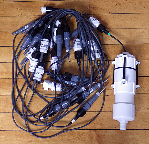
Addendum 2015: I think this is approaching the largest senor string I would want to deploy on a dive.
I recently started making long chains of these sensors, in an attempt to build a poor mans thermistor string. Here is a link to the post about those experiments.
Addendum
The DS18B20 is only supposed to draw around 1μA when in standby, and not being interrogated. So it hardly seems worth the bother of turning them on and off to me, but there are a few people doing so by powering the units directly from the digital pins of the Arduino. I might investigate that later if I have not used the pins for something more productive.
Addendum
I have also noticed that this sensor seems to warm itself if you have it doing a continuous reads at 12 bit as the script below does (which has the unit at its maximum 1.5 mA current the entire time). So just be warned that if you are using the ‘waterproof’ models, which are encased in a metal sleeve filled with epoxy, you can’t drive the sensor full tilt without internal heat building up & affecting the readings.
// adapted from https://github.com/BitKnitting/prototypes/blob/master/SensorNode433/SensorNode433.ino
// and http://forum.bildr.org/viewtopic.php?f=17&t=779
// sleep from http://www.gammon.com.au/forum/?id=11497
#include <avr/sleep.h>
#include <avr/wdt.h>
#include <OneWire.h>
const byte DS18B20_PIN=4; //sensor data pin
OneWire ds(DS18B20_PIN);
byte addr[8];
float DS18B20float;
void setup() {
Serial.begin(9600);
//Set up Temp sensor – there is only one 1 wire sensor connected
if ( !ds.search(addr)) {
Serial.println(F(“—> ERROR: Did not find the DS18B20 Temperature Sensor!”));
return;
}
else {
Serial.print(F(“DS18B20 ROM address =”));
for(byte i = 0; i < 8; i++) {
Serial.write(‘ ‘);
Serial.print(addr[i], HEX);
}
Serial.println();
}
delay (200);
}
void loop() {
DS18B20float = getTemp();
Serial.print(F(“FLOAT temp in celcius: “));
Serial.println(DS18B20float);
//Note: sensor defaults to a reading of 85 if you read it too soon after a reset!
delay (200); //just a delay to boot out the coms
}
// watchdog interrupt
ISR (WDT_vect)
{
wdt_disable(); // disable watchdog
} // end of WDT_vect
// this returns the temperature from one DS18S20 in DEG Celsius using 12 bit conversion
float getTemp(){
byte data[2];
ds.reset();
ds.select(addr);
ds.write(0x44); // start conversion, read temperature and store it in the scratchpad
//this next bit creates a 1 second WDT delay during the DS18b20 temp conversion
//The time needed between the CONVERT_T command and the READ_SCRATCHPAD command has to be at least
//750 millisecs (but can be shorter if using a D18B20 type with resolutions < 12 bits)
MCUSR = 0; // clear various “reset” flags
WDTCSR = bit (WDCE) | bit (WDE); // allow changes, disable reset
// set interrupt mode and an interval
WDTCSR = bit (WDIE) | bit (WDP2) | bit (WDP1); //a 1 sec timer
wdt_reset(); // pat the dog
set_sleep_mode (SLEEP_MODE_PWR_DOWN);
sleep_enable();
sleep_cpu ();
sleep_disable(); // cancel sleep after wakeup as a precaution
byte present = ds.reset(); //now we can read the temp sensor data
ds.select(addr);
ds.write(0xBE); // Read Scratchpad
for (int i = 0; i < 2; i++) { // Only read the bytes you need? there is more there
data[i] = ds.read();
}
byte MSB = data[1];
byte LSB = data[0];
float tempRead = ((MSB << 8) | LSB); //using two’s compliment
float TemperatureSum = tempRead / 16; //this converts to C
return TemperatureSum;
}
