Category Archives: Reducing power consumption

The goal: an operating lifespan > 1 Year on AA batteries before hardware optimization, and >2 years with both software & hardware based techniques.

Cutting Power to Secure Digital Media cards for Low Current Data Logging

This composite graph compares logger current during identical sd.begin(), File Open & File Close sequences with two different Sandisk brand SD cards on the same datalogger. The 256MB card used less than 3mAs, while the 2GB card burned more than twice as much power during this initialization. Older low cost/size cards often perform better in SPI mode, which is simply an after-thought for high end cards, because it’s required by the SD spec. Other file open/close artifacts can occur. Write methods are also a factor.

The tweaks I discuss in the  power optimization post bring sleep current on a typical build into the 0.1-0.12mA range; leaving the sleeping μSD cards  as the largest remaining power consumer on the Cave Pearl loggers.   And those cards have been a burr under my saddle for quite some time now, as they are probably responsible for most (if not all..) of the power consumption irregularities that were showing up in some of the battery voltage logs.

I already knew the various brands of secure digital media (SD) cards could have dramatically different sleep current, but a comment in the Arduino.cc forum by William Greiman (the author of the SdFat library for Arduino) made me look a little deeper at what they were doing the rest of the time:

“Performance of microSD cards is not easy to predict on Arduino.  Arduino uses SPI to access the cards and the SD library has a single 512 byte cache. Modern SD cards are designed to be used on the high speed 4-bit SDIO bus with very large (16 KB or larger) multi-block writes and reads so they must emulate the single block access that Arduino libraries use.  This can mean much internal data movement, erasing of flash, and rewriting of data.”

This shows up clearly during data save events:

These screen captures of IDE serial potter output show current drawn during a data writing event with 256mB (left) and 2GB (right) Sandisk SD cards.  4kB of CSV format ASCII data was saved, and the gaps between the writing spikes were caused by i2c coms while SDfat’s cache was filled with data retrieved from the EEprom on the RTC module. It looks like the 2GB card has to do a great deal of shuffling to accomodate the 512byte blocks coming from the SDfat library.  (Note: see our article in Sensors for more details about the the code behind this logging event)

After seeing that I tested a variety of different SD cards, finding that save event power use increased by more than 5x over the range from old 64 & 128mb Nokias to newer 2 & 4Gb Sandisk cards. There is no guarantee that any given brand’s controller will handle SPI coms gracefully, and newer cards from top manufactures often have bad SPI performance since they are are not expecting anyone to use high capacity cards with that bus.

It took me a good while to realize that I had fallen into yet another forest-for-the-trees situation, because even the worst offenders were only using ~30 mAs per save event, but all the cards were delivering similar sleep currents.  A day has 86,400 seconds in it, so the best sleepers, coming in around 70μA, were still burning six thousand milliamp seconds per day overall…

That brought me back to the question of de-powering those SD cards. I had been discouraged from trying this early in the project by some of Grieman’s other forum remarks where he suggested that there was nothing in the default SD library to support multiple shut downs & restarts safely.  But over time I found that Nick Gammon, and several others had SDcard power control working with SdFat, and seeing the folks at OSBSS claim they had power cycled SD cards more than a hundred thousand times, convince me to give it a shot.

As I had no logic level P-channel fets lying around I went with a garden variety 2n2222 BJT, configured as a ground side switch with a 30k pulldown. Driving it to saturation using a 330Ω base resistor (assuming Hfe = 30) should give me enough wiggle room to handle spikes up to 150mA, though it will burn another 10mA to keep the BJT on for the full second I needed to wait before pulling the plug.  Write latencies for SD cards can be quite large, and some cards have more than one stage of sleep, drawing around 1.0 ma for maybe a second before entering deep sleep.  But with 6000 mAs/day on the other side of the scale, I could afford the extravagance.

The cross leakage stuff I’d seen on EEVblog convinced me that I needed to actively pull up all of the SPI pins after the ground was disconnected. I cobbled together a set of  ON/OFF functions with pinmode commands, but it did not work reliably until I switched over to port manipulation (like they did at OSBSS), so the lines were all pulled simultaneously.  I was already disabling peripherals like the ADC with the PRR register, but that was just to save a little runtime power. Now it was required because when SPI is active, it controls MISO,MOSI & SCLK.  So you must shutdown the SPI interface before you can set those pins directly.

#include <LowPower.h>
#include <avr/power.h>
#include <SPI.h>
#include <SdFat.h>
SdFat sd;                                   // Create the objects to talk to the SD card
SdFile file;
const byte slaveSelect = 10;   // sd card slave select on pin D10
#define SDpowerPin 9            // pin controlling the BJT on the ground line for the SD card
boolean SDcardOn = true;     // flag for error routines
byte  keep_SPCR;
// spacer comment for blog layout
void setup () {
keep_SPCR=SPCR;                  // save the default SPCR register contents
 
// the following pullup steps are all optional:
// turn on internal pullups for three SPI lines to help ‘some’ SD cards go to sleep faster
pinMode(slaveSelect, OUTPUT);
digitalWrite(slaveSelect, HIGH); //pullup the CS pin on the SD card (but only if you don’t already have a hardware pullup on your module)
pinMode(11, OUTPUT);
digitalWrite(11, HIGH); //pullup the MOSI pin on the SD card
pinMode(12,INPUT_PULLUP);//pullup the MISO pin on the SD card
pinMode(13, OUTPUT);
digitalWrite(13, LOW); //pull DOWN the 13scl pin on the SD card (IDLES LOW IN MODE0)
// NOTE: In Mode (0), the SPI interface holds the CLK line low when the bus is inactive, so DO NOT put a pullup on it.
// NOTE: when the SPI interface is active, digitalWrite() cannot effect MISO,MOSI,CS or CLK. . . }

void turnOnSDcard() 

 {
pinMode(SDpowerPin, OUTPUT); digitalWrite(SDpowerPin, HIGH); //turn on the BJT on SD ground line
delay(6);                                            // let the card settle
// some cards will fail on power-up unless SS is pulled up  ( &  D0/MISO as well? )
DDRB = DDRB | (1<<DDB5) | (1<<DDB3) | (1<<DDB2); // set SCLK(D13), MOSI(D11) & SS(D10) as OUTPUT
// Note: | is an OR operation so  the other pins stay as they were.                (MISO stays as INPUT) 
PORTB = PORTB & ~(1<<DDB5);  // disable pin 13 SCLK pull-up – leave pull-up in place on the other 3 lines
power_spi_enable();                      // enable the SPI clock 
SPCR=keep_SPCR;                          // enable SPI peripheral
delay(10);  SDcardOn = true;       // just a flag // may need to extend this delay with some cards
}

void turnOffSDcard() 

 {
delay(6);
SPCR = 0;                                         // disable SPI
power_spi_disable();                     // disable SPI clock
DDRB &= ~((1<<DDB5) | (1<<DDB4) | (1<<DDB3) | (1<<DDB2));   // set All SPI pins to INPUT
PORTB |= ((1<<DDB5) | (1<<DDB4) | (1<<DDB3) | (1<<DDB2));     // set ALL SPI pins HIGH (~30k pullup)
// Note: you must disconnect the LED on pin 13 or you’ll bleed current through the limit resistor
LowPower.powerDown(SLEEP_1S, ADC_OFF, BOD_OFF); // wait 1 sec for internal SDcard housekeeping 
delay(6);
pinMode(SDpowerPin, OUTPUT); digitalWrite(SDpowerPin, LOW);  //turn off BJT controlling the ground line
delay(6); SDcardOn = false;


These two functions book-end any code that needs to write data to the SD cards:

turnOnSDcard();    flushEEpromBuffer();    turnOffSDcard();

That SD card data saving function starts by checking the main battery to make sure there is enough power to save the data without a brown-out, and then re-initializes the card with sd.begin before opening any files:

vBat = readBattery();   // This function shuts down the logger if the main battery is below 3.65V
if (!sd.begin(chipSelect, SPI_FULL_SPEED)) {
Serial.println(F(“Could NOT initialize SD Card”));Serial.flush();
error();  // note: the error event includes:  if (SDcardOn) {turnOffSDcard();}    inside the function
}
delay(10);
file.open(FileName, O_WRITE | O_APPEND);  //see this post by Grieman
//…save your stuff…
file.close();


Looking at the datasheets for the Mic5205, or the Mcp1700,  you see the regulator dropouts can reach 300mV at 100mA+ currents you could see during SD card initialization, so your input cutoff for a 3.3V system needs to be above 3.65V to handle the load.   After the data is saved it is critical that all open files are closed properly before the turnOffSDcard function gets called, otherwise your data will be lost. The graphs tell me that a full one second delay before powering down the card is probably longer than it needs to be,  but in data logger applications it’s pays to err on the side of caution. According to Greiman:

“The standard says reliably removing power is not supported in SPI mode. It does suggest that you can remove power one second after the card goes not busy but does not guarantee this will work. You can’t depend on isBusy() to power down a card. It only means the card can accept a command. It may still be programming flash or moving data for wear-leveling. You really need the one second delay after not busy.”

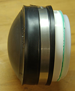
Lately I’ve been using these 60¢ SD adapters, and removing the bottom three 10k smds that these boards have on the SCLK, MOSI & MISO lines. (the other resistor keeps the ‘RSV’ pins from floating) Having a pullup on the clock line wasted power during mode o sleep as the clock idles low, but now that I’m cutting power rather than just sleeping the SD cards, I could leave those resistors in place…then I wouldn’t need to pull up those lines in the code, (though I’d still have to pull SS…) Thing is, Grieman says SPI should not have pull-ups or pull-downs on MISO, MOSI or SCK. So I’ll stick with the 328’s internal 25k pulls for now, because doing it in code is reversible. But that does leave some pins floating during the boot process.

Of course, it was pretty flakey the first few times I tried it. Half of the loggers worked, but the other half were restarting every time there was a data save event (killing off SD cards in the process…) This problem affected every logger built around the Rocket Scream Ultra, which has been one of my favorite small form factor boards.  Closer examination of the two-penny clones that were working ok revealed that they had 10μF tantalum capacitors beside the voltage regulator rather than the little 1μFs beside the Ultra’s MCP1700.  So those cards were hitting the rail pretty hard when the SD ground line was re-connected, and this caused brief transients that were low enough to restart the processor on half of my units. Some add a small (33Ω) resistor in series to limit these inrush currents, but I found that adding 2-3 10μF (106) ceramics to buffer that spike got them all working ok, and for field deployment units I’ll probably add more.

I set a several units running on the bookshelf, with a rapid six second sampling interval. A couple of weeks later they were all still going, with some of them seeing more than 30,000 SD card power cycles without error. Given that the loggers normally see less than one save event per day, I’m calling that a successful test. If you run into issues, the first thing to try is extending that delay after sd.begin() and adding a few more delays throughout your functions. If you look at the spec you find that SD cards are allowed to take huge amounts of time for everything from initialization, to file open/close. While I did not see that in cards I used for my tests, these latencies are ‘officially’ allowed to stretch well beyond 100ms.

With both pin-powering on the RTC, and ground line switching on the SD card, the loggers get down to between 0.03-4mA between samples, which should push my operating lifespan into multi-year territory. Or, if I’m really lucky, they’ll make it through one winter-time deployment in Canada 🙂

I was also pleased to discover that the On/Off code seems to work on loggers that do not have the ground side switch installed provided I do not try to re-initialize the cards with sd.begin.  SPI shutdown & line pullup seems to cause the SD cards to enter sleep mode more quickly than they did before, and I have not seen any current leakage. So hopefully I won’t have to maintain vastly different code versions for older non-switched loggers. (Update 2017-06-12: Further tests of SPI shutdown, without the BJT to disconnect power from the SD card have not been reliable. Some worked, some didn’t. When I figure out why that is I will post an update)

Addendum 2017-06-06

A commenter over at Dangerous Prototypes made a point about my use of the 2n2222 which is important enough that I should pass it on:

“I’m surprised he didn’t check the 2N2222. Look at its data sheet, the V(CE) performance is not great. Take 0.3V at 100mA, then the SD card would have been actually running at 3.0V, right at the -10% VCC rating edge. I’m surprised the problems are not worse. Of course it would be extremely sensitive to VCC sag…”

The drop across the collector-emitter was something I had simply missed, and I still struggle to read those datasheet graphs properly.  And I was so used to seeing card operating voltage specified between 2.7-3.6v, that I also missed the fact that in SPI mode, only 3.3v is officially supported. The net result is that I’m probably sailing closer to the wind here than I realized, and I’m going to call this technique “experimental” until I see real-world deployments saving more than a year of data safely. And if I stay with ground-side switching in future, I will start looking for a good logic level N-channel  MOSFET, with low on resistance, to replace that BJT. The Supertex TN0702 looks like a good option with the promini’s with 3.3v logic.

Addendum 2017-06-06

This card gets thrown straight into the garbage.

Just thought I should post a reminder to test your SD cards thoroughly before embarking on SD power shut down experiments. I use SD formatter v4.0 & H2testw.  An occasional check with H2testw after deployment is also a good way to make sure that you are not damaging your cards over time…


Addendum 2018-03-22

I’ve been doing more experimenting with de-powering the SD cards during sleep.  It works great most of the time, but I was still seeing a few frustrating re-boots on some loggers when the SD power was restored. To get to the bottom of this I set up a unit repeating a standard SD data-save cycle and looked at the current through a shunt resistor with my Arduino DAQ.  The results made it pretty clear what was happening:   (click image for larger versions)

Kingmax 128mb  (40mA peaks,  25mA sustained ~60ms,  best performance of all cards tested)

Nokia 256mb  (50mA peaks, 35mA sustained ~40ms)

Nokia 128mb  (65mA peak,  35mA sustained ~200ms and 55 mA sustained 2x 100ms)
[these artifacts occurred during every single save, and on the other Nokia 128mb cards tested]

Sandisk 512mb  (75mA peaks, 50mA sustained ~60ms)

Sandisk TRANSflash 128mb  (150mA peaks, 90mA sustained ~80ms)

SanDisk 2Gb  (90mA peak, 55mA sustained ~350ms)

NONAME 1Gb   (110mA peaks,  90mA sustained ~45ms)

SanDisk 32Gb Ultra  (110mA peaks, >110mA sustained ~200ms)

MUVEmusic 1Gb(+3Gb)  (>110mA peaks, >110mA sustained ~400 ms!!! )

All these tests were done with the same code, on the same logger – only the cards were changed.  All of the cards shown above were successfully saving the data to the CSV file. I was using a fairly large 10 ohm shunt, with the internal 1.1v as Aref so those clipping plateaus at ~110 mA were a limit of my method. The SD spec says cards can actually draw up to 200mA during initialization events, and I suspect those last two get up to at least 150mA.

Given the huge difference between the peak currents, and the size of the sustained power loads, it’s not surprising that some of the loggers were suffering from brown-out restarts. A few caps could buffer the short spikes, but those larger sustained loads were too much for the MCP1700’s I’m using.   Another thing that’s important to note here is that (with the exception of the 32Gb) these cards were selected from a batch that I had already tested for low sleep currents.  So it looks like I’ll have to retest all cards that are destined for the low-power logger deployments that de-power the SD cards. Generally speaking it’s still better to stick to the older 256mb cards, though some of those have strange housekeeping events at every data save. It’s all just a reminder that SD memory is actually more complex than the Arduino since the card itself may contain a 32 bit arm core.

Addendum 2018-10-03

I’ve a new crop of identical drip loggers running through pre-deployment testing with the same code.  Since these units were de-powering the SD cards between saves, I didn’t worry too much about which cards I put in the units figuring that a few intermittent power loads would not affect the operating lifespan very much. 

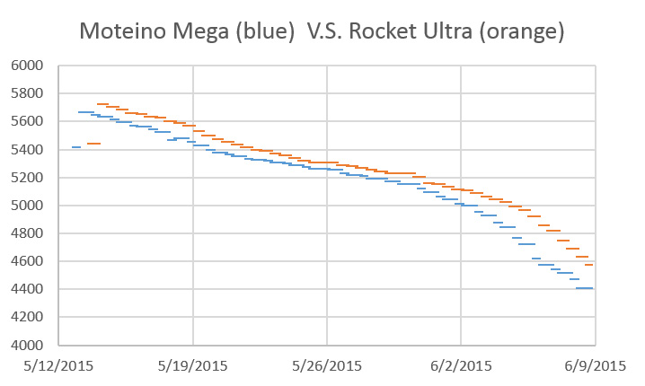
In the following records I read the battery voltage every 15 minutes (the blue line) and also track the “lowest” battery reading during logger events like SDcard saves (the orange lines)  with small daily saves, and a big data transfer event about every 5 days.  The 15 minute record is quite variable as the AA alkaline battery voltage responds to the ambient temperature in the room.

This first graph is from a logger with a Nokia 256mb SD card, and the lowest main battery readings hold within 50mv of the typical readings:

and this record is from a logger with the generic 1GB sd card shown in the earlier graphs:

The width of those drops is an artifact from the fact that “lowest reading per day” variable only gets reset at midnight. Since there’s a 5-10ms cap stabilizing delay in my ADC reading function, and the SD code is blocking during the high-drain card initializations, it’s likely that the maximum voltage drop on those cells was  larger than the 250mv that showed up in this record. Any main battery reading that approaches the main regulators minimum input voltage sends the loggers into a controlled shutdown, so those dips could result in a significant amount of missed run-time by triggering the shutdown too early. If you can’t get your hands on those old Nokia cards via eBay, I’d suggest you use lithium batteries to avoid this voltage droop issue when using larger, newer, micro SD cards. The tests I did with lithium cells showed virtually no SD writing drops no matter which card was in the unit, and this effect will no doubt be amplified when deployment temperatures approach zero degrees Celsius.

Addendum 2020-04-11

Wanted to add a note that on our recent builds with no regulators – running directly from 2x LITHIUM AA batteries – we have not yet been able to detect any voltage dip on the main battery during the big transfer of data stored in the eeprom buffer, out to the SD cards.  And that’s with no buffering capacitors other than those already on the ProMini module. This is notable because most of our MCP1700 regulated builds see a 200-300 mv drop on the main cells with Alkaline batteries. Also tested those same regulated builds with lithium batteries and the SD writing dip went away – so it’s definitely the alkaline chemistry struggling to keep up with the speed of the pulse load generated by the cards.

Also, here’s a link to someone testing a batch of new large-size cards.  Some with current draws significantly larger than the old 256 & 512mb Nokia cards we use.

Addendum 2020-12-20        Ahhh the IEEE . . . Better late than never, Eh?

Optimising SD Saving Events to Maximise Battery Lifetime for Arduino™/Atmega328P Loggers

“The exact power consumption of an Arduino/SD card during saving events is analysed for the first time…”

Ummm…really? And with such pithy gems as buffering to SRAM to reduce SD writing events? Never would have though of that.

When you run power tests on several different SD cards you discovered the real problems: There is enormous variability between different brand/type cards wrt both the power and the time they need to initialize.  And then theres what I call  ‘super housekeeping events’ which are significantly longer than power-up initializations. These are hard to capture because they get triggered at different points depending on the cards internal code and how this interacts with the previous power and usage pattern: but the SD card essentially turns into a solid block of maximum power draw for several hundred microseconds.  This is why we say our loggers can only sample at a max rate of 1Hz – because you never know when you are going to hit one of those blocking events and hang your logger. If you monitor your battery voltage closely you will see the unmistakable aftereffect of these high drain events in the record periodically.

Also, some cards are ok with SPI access, and some cards absolutely are not cool with it. When you use a card that does not like SPI access it will still “work’ but each save triggers massive internal memory juggling no matter how much data you actually write to the card.  Again – essentially a solid wall of current.  So far the best performers with our loggers seem to be older 256Mb to 1Gb Sandisk or Nokia cards because it was not unusual for that generation of cards to be accessed in SPI mode.

Even our basic student logger only pulls ~250μA while sleeping with an SD card. Clipping Vcc on the RTC typically gets that down to ~150μA and a good SD card will get you below 100μA for the entire logger. So I can’t say they did a very good job on the power optimization before adding the mosfet.  When you implement SD power switching a ProMini logger gets below 30μA, with some getting below 20μA if your sensors have low current sleep modes. At that point the main problem with your logger is that alkaline batteries ‘age out’ after a couple of years in service (due to pressure or thermal cycling?) and start leaking long before you’ve used even half their rated capacity.  But I’ve no doubt someone will publish that ‘for the first time’ in another IEEE paper… in about 5 years.

And don’t set all your logger pins to OUTPUT as the recommend in the paper: the power saved is negligible and INPUT mode protects against accidental shorts.

Addendum 2022-08-07: Testing SPI mode on larger cards

MicroSD Card Power Consumption & SPI Performance found big differences between average and worst-case latencies, which are likely attributable to internal card housekeeping operations.

Measuring battery discharge on an Arduino Data Logger

I’ve written before about how the main battery discharge record is one of my primary tools to determine what happened when a logger fails, but I thought I would try another kick at that can; delving into some of the things that show up on units that are apparently running OK, but still leave me scratching my head.

I did not really know how to solder at the beginning of the project, so I was using Tinyduino based platforms that drew sleep currents between 0.5-0.6 mA. I was running them right from the battery with no voltage regulation, and using the 328’s internal 1.1v band gap trick  to track the power supply:

Battery Voltage (mV) with

Battery Voltage (mV), 2 x 3AA battery pack, Tiny Duino based logger

These units buffered less than half a day of readings to the small 4K eeprom on the RTC breakout,  so I attributed most of that 100 millivolt  jitter to the frequent SD card writing. Some have pointed out that the internal voltage reading trick itself can suffer from as much as 10% variability from one processor to the next, with additional thermal variations. But at least those curves were predictable, with a 6 cell (2x3AA) pack lasting longer than the four months between fieldwork trips.

The need to provide regulated power to an increasing number of sensors encouraged me to switch over to 3.3v pro-mini style Arduinos,  and adding a 32K external eeprom extended my buffering out to several days. This smoothed the power curves dramatically, and on good builds I now see voltage records like this:

Cave Pearl data loggers

Battery (mV), Rocket Ultra logger, 3xAA Battery, 0.19mA sleep

The steps on that curve correspond to the limits of the ADC (with a 2 x 4.7MΩ divider cutting the battery voltage in half), so that’s as good as I’m ever likely to see. The thing that has me curious is that I also see curves that look irregularly bumpy, and have other intermittent features. For instance, some of the loggers built from the same parts, with the same code as the one above, give me a clear pattern of 100mV dips whenever the data gets transferred to the SD card:

Battery (mV), Rocket Ultra, 2x 3xAA supply

Battery (mV), Rocket Ultra logger, 2x 3xAA Battery, ~3 day buffer

As you see the depth and duration of the dips vary somewhat, although the amount of data being written is always exactly the same, which makes me wonder about random latency delays. And that curve also has a mysterious low voltage anomaly showing up around 9/20 that lasted for the better part of a week.  I see stuff like that in about 15% of the loggers that give no other sign of problems, have low sleep currents, and decent operating lifespans. And this is definitely not temperature related, since most of the cave loggers see less than 1°C variation over a deployment.

Other times I see hump shaped features in the curve that seem to indicate that the problem occurred long enough to pull the batteries down significantly, but then went away, and returned again some time later:

Battery (mV), Moteino based logger, 3xAA supply, 0.22 mA sleep

Battery (mV), Moteino based logger, 3xAA supply, ~5day buffer, 0.22 mA sleep

I took this unit out of service, and am running tests on it now to try to identify what happened. Again there was no hint of a sensor failure in the data, and the sleep current still looks the same as it did at the start of the deployment. I’ve seen this hump/step pattern a few times now, and for all I know it’s an issue with the batteries hitting some kid of threshold, rather than the logger. 90% of my deployments use alkaline AA’s, as I usually catch them on some kind of promotional sale at the local hardware store. I rarely use lithium AA’a as they are more expensive and I’m not convinced they give you longer operating life in low current applications.  They also fall so precipitously at the end of life that I am concerned they will brown out in the middle of an SD card operation, destroying my data before the code has a chance to intercept the low voltage problem. (…and they are not allowed in air travel luggage …)

Probably the longest running power curve mystery are the events that only show up once every month or so. These hits are so widely spaced that they don’t seem to be directly related to the buffering & regular SD card writing events, and I have yet to find anything else in the code that explains them:

Battery (mV), Rocket Ultra, ~3day buffer, New file @~15 days

Battery (mV), Rocket Ultra, ~3day buffer, New file @~15 days

The timing of these long gap events can be regular, as shown above, or more variable. My current hypothesis is that some threshold is being passed inside the SD card controller triggering some kind of huge load balancing event that hits the battery with a sustained power draw much larger than any of the normal logger operations. This makes me wonder if the battery packs would benefit from a parallel supercap to buffer those pulsed loads.  I suspect that the SD cards are responsible for most of the power curve anomalies that I’m seeing. All the loggers are now using Sandisk’s MUVE music SD cards that quickly go into low current sleep, so I am still left wondering what the real cause is.

Anyway, I’d love to hear comments from others who have seen curves like this in ‘otherwise normal’ equipment.

Addendum 2016-03-02:

Just thought I would add another interesting one to the batch. When I build a new logger I like to put them on a shakedown test for a week or two, with rapid sampling and small eeprom buffers to make sure the SD card sees lots of activity to test it out.  So this is in no way a “normal” operation power consumption curve like the ones posted above but it does show another interesting phenomenon:

This unit was taking a sample every 5 minutes, and only buffering 20 readings to the eeprom.

This unit was taking a sample every 5 minutes, and with only 20 readings buffered to the eeprom those numerous 100mV spikes are from the frequent SD write events.

This was a continuous run, so the code did not change even though there was a fairly dramatic shift of the pattern in the voltage readings. Usually I see this kind of thing in reverse when a sensor fails (ie: a smoother curve becoming more and more variable as the sensor goes down).  I have no idea what caused this unit to become more regular as the run progressed?

Addendum 2016-04-07:

Found anther one to add to the collection.  This flow meter is still in service, though the overall curve is crunchy enough to make me suspicious that something is going on, the logger has not replicated the central up/down anomaly in any subsequent deployments:

Caption

Battery (mV), Rocket Ultra 8mhz, ~5day buffer, New file @~15 days

Addendum 2016-04-07:

I monitor the main AA supply with a simple  2 x 4.7MΩ divider  on an analog pin, but Dangerous Prototypes spotted a low voltage indicator circuit that can be built from a couple of comparators. This could come in handy for builds that don’t have enough pins left to keep track of Vbat. This would be handy for minimal builds with AT Tiny’s. There is also some interesting background info on battery discharge curves with boost converter in this TI appnote.

Addendum 2016-07-30:

Reviewing the data from the latest round of fieldwork, and have another interesting power curve to add to the collection:

Rocket based logger,

Rocket Ultra 8mhz based logger, 3xAA, 15min sample, 512 records buffered to eeprom

That’s the first time I’ve seen higher voltages appear in a record where the logger was in a stable thermal environment, and it makes me wonder how that might of occurred. Since there was no change in the cave temperature, I suspect that the voltage regulator on the Arduino had a few low voltage events, and this messed with Aref enough to create artificially high readings on A0.  All the other data in the log appeared to be fine, but I will be keeping my eye on this logger…

Addendum 2016-09-12:

shottky1n5817This is a bit of a tangent, but I’ve been using bog standard 40v 1A Shottky 1N5819 diodes to isolate the 3xAA battery banks on some of my loggers, and I just noticed in the datasheet that 20v 1N5817’s have about 1/2 the Vf. And I just found out that with beefier 3A diodes, I can probably bring the voltage drop even lower during SD card write events, which could push the logger below the 0.1 A line at the bottom of this graph. This makes me wonder how much of the voltage dips I’ve been seeing are a real effect of the load on the battery, and how much is simply an artifact of the isolation diodes?

Addendum 2016-10-17:

1n400x15Continuing on the diode tangent, I’ve recently come across a few mentions of powering Arduino projects with 4xAA batteries in series, using a 1N4001 diode to drop the voltage into the 5.5v range you see on some 3.3v Arduino regulators. I have yet to find any tests of exactly how much power you would be wasting over the diode, vs the extra power you could extract by taking 4 cells down to about 0.85v  than you could with 3 cells in series (~1.16v) . The circuit would cause a voltage fluctuation of about 0.2 volts but I don’t know if that is worse than the Shottkys, as their datasheet does not go down to very low current levels. It’s worth noting that the MIC5205 on the ProMini is rated to 12v input but that comes at the cost of another 0.05mA sleep current which would burn away the benefit of that extra cell fairly quickly.

Addendum 2016-10-27:

EEVblog #140 – Battery Capacity Tutorial
EEVblog #772 – How To Calculate Wasted Battery Capacity

That last one makes me  less concerned about the LDO regulators relatively high 3.5v cutoff when using 3xAA’s, but even more concerned about the curves that show a 100mv pulse discharge drop during SD writing. If those events trigger the low voltage shutdown too early that would loose a significant percentage of the overall battery capacity.  Perhaps the best solution would be to switch to the MCP1703 regulator which accepts up to 16 V, then I could use 4xAA batteries and avoid that diode loss problem. It is available with 3.3V output (MCP1703-3302E  & the SOT23-3 boards to mount them)  although some people have had problems with the 1703 in low power applications. Having the extra input voltage space would let me try putting 3.6v lithium cells in series, which you can buy in “D” size with a whopping 19Ah. Of course with  lithium discharge curves being so flat, I might get away without the regulator at all: I just don’t know how sensitive the SD card would be to that drop at the end, and it’s not worth risking data to find out…

Addendum 2017-02-23:

I finally started tracking down those SD card wear-leveling events with my Uno-scope. It’s hard to catch ’em because they don’t get triggered very often, but after setting a unit to constantly loop through a repeated sequence of short data saving events I managed to snag one:

This is just a brief one, but perhaps others last long enough to cause one of those dips in the voltage log?  I read the battery voltage before and after the data saving, so if the SD card does that kind of housekeeping after the file close event is complete, then SDfat has released the code block and I could be doing that second battery read while the SDcard has the current drain at up near 60 mA or more…


Arduino Pro Mini Data Logger : Part 4 : Power Optimization (2015)

The first three tutorials in this series show how to build a promini based data logger that should sleep around 0.25mA, depending on the quiescent current of your sensors and your μSD card. That will usually get you to at least 6 months of operating life before a bank of three AA batteries in series falls below the 3.5v cutoff on your regulator, and most of our field units make to about 11 months on a good quality set of alkaline AA’s. With their flatter discharge curve, lithium AAs would probably have carried those logger past 12 months,  but if you really want the logger to pass one year of operation you need to do a few other things that might be a bit of a stretch for beginners.  So I am posting them here as “additional” things to tackle once you have built a few of the basic loggers and have them working Ok.  Use the cheap parts till you get the hang of soldering and working out how you want your cables & housing to go together physically.  I find that things usually go well the third time I make a new prototype.

A DIY data logger

Usually takes me about 20 minutes to assemble, or less with solderless headers. At any given time I probably have 6-8 of these breadboard loggers running on the bookshelf to test different hardware and code combinations. Be careful not to bump the SD card connections though, as its easy to kill the card with unexpected power interruptions.

Without question the most important thing you can do to extend the life of your data loggers is to build yourself a breadboard “testing platform”.  This lets you determine the sleep current for each component on it’s own, making it easy to spot fake SD cards, or bad sensor breakout boards. And even good SD cards wear out with time , or are  damaged by high temperatures. Checking that cards and boards go to into a low current modes properly (after the main mcu sleeps) is the best diagnostic I have found to determine if the components are Ok. Good SD cards sleep between 0.05-0.07 mA, and these tend to be older Sandisk 128mb cards. Typical cards pull between 0.07-0.09 mA while sleeping. Any more than than that and I simply do not use the card in my data loggers. The difference between a good sensor breakout board and a bad one can be even more extreme, and you should always look for breakout boards that have a native 3.3v input line to avoid regulator losses. I already mentioned pulling up three of the SPI lines, and the breadboard unit lets you easily test how other pin configurations affect the logger. Pin states are generally preserved during sleep, though any timer dependent functions (like PWM) will be shut down when the associated timer stops, unless you use ‘idle’ mode.  Always avoid floating I/O pins.

Retrofit an MCP1700 voltage regulator to an ebay clone

All you have to do to retrofit any 3.3v mini-style board with a more efficient MCP1700 is connect the external regulators output directly to the 3.3v pin, which is the main power rail behind the default voltage regulator. This by-passes the onboard Vreg the same way that your UART board does when you are tethered to USB. When I do this modification I completely remove the original regulator from the Arduino board so there is no leakage current slipping through it while the logger is sleeping.  Also be sure to move the high side of the resistor divider you have monitoring the battery voltage to the new regulators Vin line. Replacing the MIC5205 with a MCP170x will save you ~0.05 mA of sleep current, depending on your particular board. That doesn’t sound like much, but it all adds up over time, and you have 100 mA more current available to power your sensors.

When you test your components individually you notice that there can be significant differences from one pro-mini board to the next (especially with cheep eBay clones) and much of this comes down to the voltage regulator. Sparkfun Pro-mini’s use a Micrel  MIC5205 150mA LDO Regulator, and there are more efficient options out there. I have had success with boards that use MCP1700  & MCP1703 regulators (datasheet) like the Rocket Scream Mini Ultra or the Moteino. Each board has a unique pin-out, so you will have to figure out where to put the jumpers for each particular board.  You can also simply bypass the pro-mini’s on-board regulator and use an external voltage regulator (see the image posted at the bottom of that thread by fat16lib – don’t forget the 1 µF caps.  MCP1700s @ < $0.50 ea here ).

Sleeping your processor & components at every possible opportunity is vital. If there is a power wasting delay statement left in your code anywhere, there ought be a really good reason for it (like waiting for your ADC reading to stabilize, etc)

YL-90_AT24C32eeprom1

You can flick the SCL and SDA pullup off the board easily with the tip of a soldering iron.

The next life extending technique is to add a larger I2C eeprom so that you can buffer more data before you write to the SD card. The functions I use to do this buffering is included with the I2C eeprom tester example I posted to gitHub.   Eeprom power consumption limits to how far you can take this strategy, but switching from the 4K AT24C32 on that RTC breakout to a 32K AT24C256  provides a $1 way to extend your operating life by 5-10% depending on the amount of sensor data you are handling. The two eeproms are from the same Atmel family, and the wire.h I2C library limits you to 32 byte page writes, so all you have to do is change the bus address in your code and you are done! Same applies to the AT24C512 all the way up to the 2Mb AT24CM02 if you can find them. You can also lift & jumper the address pins (A0,A1) to enable up to four of these Atmel boards on the same bus. (and it would require some code tweaking, but you might also be able to swap some of the larger Microchip brand I2C eeproms into the cheap press fit DIP boards if you wanted bigger chips to play with. Or you could just roll your own breakout board  for a whopping 1024Kb with the 24LC1025 and the 24AA1025 ) The logical end game if you go down the eeprom road is to abandon simple ASCII and start working with struct’s in C.  Then you could store a years worth of data without any SD cards at all.

 .
Isopropyleeprom1. Remove the two pull-up resistors from the YL-90 breakout (if that’s the one you are using ) as the RTC board pull-ups are sufficient.  Straighten the riser pins and trim them to about 1/2 length.

2. Cut 2” lengths of Black, Red, Yellow, and White wire. Solder them to GND, VCC, SDA, and SCL respectively. Shrink wrap the solder joints.

3. Clean the board with alcohol and let it dry.  Apply conformal coating if desired and put a patch of double sided tape on the bottom.

jumpering the eeprom board

4. The next step is to adhere the eeprom to your logger platform via the tape, so that you can cut the jumpers to length. If you left some excess wire protruding from the board when you added the bus interconnect for the sensor cap, it’s pretty easy to patch the four eeprom wires right onto the cascade port.


Sleeping & buffering are the low-hanging fruit, and after that you get into trickier techniques to improve the power budget. For example that new eeprom also lets you push the bus speed above the 100kHz default if your other I2C devices can handle it. I am still testing prototypes at 400kHz, even though that violates the Tlow spec on 8mHz AVR processors, so I am cautious about recommending that to everyone until I see those units deliver a year of good data. But the results have been promising so far...

Cave Pearl data loggersAnother useful modification is powering the RTC from a digital pin. For some reason I have not been able to dig out of the data sheet, the DS3231 pulls almost 0.1 mA when it is powered by the Vcc pin. Fortunately, you can force the IC into a miserly 3μA timekeeping mode if you draw that Vcc pin down, and if the Battery-Backed Square-Wave Enable register bit is set the RTC will still generate alarms when running off of the backup battery. But the soldering for this is a bit tricky:

Cave Pearl data loggers1. After removing the power LED & charge circuit resistors from the RTC board, wedge a fine tweezer tip behind the power pin and apply an iron to the pad on the board. When the solder melts gently lever the pin away from the board.

2. Then tin the pin, and solder a jumper wire to the lifted power pin, being careful not to bridge any of the other connectors in the process. I usually secure the jumper wire to the board with a zip-tie so that no physical stress can be transferred to that tiny solder connection later.

Cave Pearl data loggersAt that point you can attach the jumper to a free digital pin on your Arduino, and use digital.write(pin#,HIGH/LOW) to power to the chip only when the logger is awake.  My pin-powered builds have eight months under their belt now, and by spring 2016 I will know if the CR2032’s can provide enough power to drive the RTC in timkeeping mode for a full year. (2016 note: they all made it!)  I am trying to track the coin cell status with another voltage divider on the breakout board, but since lithium cells keep their nominal voltage until they are completely dead unless you provide a load, that record might not give me any useful information. I will post updates on those experiments on my RTC page as they become available. (Note: Even with the default MIC5205 reg on the promini, pin-powering the RTC like this should get your logger down to ~0.17mA sleep current)

By testing components, changing regulators, buffering, and pin powering the RTC, I am now seeing power curves like this:

036_inCave_PR&RH_20150324-0806

This unit had a TMP102 temperature sensor,  an MS5803-02 pressure sensor, and an HTU21D RH sensor attached, and it still took four months to burn off the over-voltage on 3 AA Duracells. (with a 15 minute sample interval) The logger slept at 0.15 mA because all those sensors all have great low power sleep states.

Though I have reached my original one-year goal, I still keep an eye out for other ways to save power. Several people have explored using a MOSFET to de-power the SD cards but according to the fellow who actually wrote the SdFat library, there are some issues wrt multiple re-starts of the SD library . He also warns that you have to close all files and allow at least one second for the SD card to power down before pulling the plug, just in case you accidentally trigger some internal housekeeping event with the file close command.  The folks over at OSBSS claim they can switch the low side without problems and Nick Gammon seems to be having success with his THL logger switching the high side, though those two examples leave me wondering which way to go.  Some set all the SPI lines HIGH & INPUT before powering down to prevent parasitic leakage after the cut, though the guys at Solarduino imply only the slave select line is vulnerable to the problem, and suggest that line won’t leak if you switch the low side (?)

Another potential factor is low 3.3v I’m using to control the FET, discussed here at  CMicrotek’s Low-power Design Blog:

“When using a P-channel FET to drive a load, a GPIO may not drive the gate high enough to completely turn off the FET so you may be leaking power through the FET. This can often go un-noticed since the amount of power is too low to activate the load. A P-channel FET of similar rated voltage and current as an N-channel FET will typically have 50-100% higher Rds(on) than the N-channel FET. With Rds(on) specs on modern FETs in the double-digit milliohm range even doubling the Rds(on) produces a fairly low value. However, that is simply wasted power that can easily be eliminated if low-side switching is an option for your application.”

Reading that makes me lean towards low side switching; though the 2n7000s in my parts bin probably can’t be fully turned on with only 3.3v on the base?  (Note:  there are beefier N-channels out there  that will work with a 3.3v system if you are also de-powering high current sensors)  Luke_I has proposed using SPI.end() to kill all SPI communications once all files are synced and closed but most people simply set the SPI control register SPCR=0;   When you restore power  after low side switching you have to reset SCLocK(D13), MOSI(D11) & CS back to OUTPUT (MISO stays at input) and set the SCLock line LOW to disable that pullup.  Then you reinitialize the SDcard with sd.begin(chipSelect, SPI_FULL_SPEED);  and reopen your files.   Several sources have suggested that only SdFat allows this re-initialization , while SD.h does not.  

One possibly important thing to note is that the sandisk datasheets states (pg 11) 

“Power must be applied to the VDD pin before any I/O pin is set to logic HIGH. In
other words, CMD, CLK, and DAT0-3 must be at zero (0) volts when power is
applied to the VDD pin. “ 

But perhaps this only applies when accessing the cards in their native SDIO mode? But this does make me wonder if you are supposed to turn on the mcu’s internal SPI peripheral before, or after you restore power to the SD card (?)  I think that datasheet suggest you should be doing it after, but they are switching the high side in that example case.

You can extend that strategy and cut power to the entire logger. As I mentioned in the RTC post, the most elegant way to do this would be using the RTC alarm (outputs low) to control a P-channel Mosfet on the high side of the main battery supply.  When the INT/SQW alarm goes low, this turns the mosfet on and powers everything including the main mcu board which would then goes to work taking samples and storing data. Unfortunately some of my builds use interrupts from both the RTC and the sensors, and there is a good chance that with these frequent startup initializations the resulting delays could miss the phenomenon I was actually trying to capture; like tipping bucket or wind sensor reed switches.

Addendum 2016-02-06

Just thought I would post another shot of a retrofit with an MCP1700 voltage regulator:

Cave Pearl data loggers

Note: I used a 6 volt input MCP1700 here, but the MCP1703-3302E/TO accepts up to 16v

…with the addition of a 2 x 4.7 M‎Ω  voltage divider to put 1/2 of the RAW input voltage on A0. Note that the onboard vreg has been removed (normally you would see it just under the cap in front: you can see some of the empty pads still there) and the two led limit resistors have also been pulled. Other than the mcu there is not much left but the crystal & some caps, and I now think of the board itself as simply a convenient breakout for the 328p. This retrofit with an MCP1700 looses the shutdown enable functionality of the default MIC5205 (marked KBxx or LBxx), and the noise suppression features, but I am hoping the caps are enough to deal with that.  The 1700’s are more efficient at low power than the 5205’s which limp along at about 20% efficiency below at 0.1mA, and loggers typically spend 99.9% of their time sleeping.  The XC6203E332PR is another low-ish standby power option if you need output currents in the 400mA range.

On more recent builds I have started moving the voltage regulator & battery divider from the Arduino board to the battery connectors. Note the ceramic 105's on the MCP1700 as per the proper spec.

On late 2016 builds I started moving the  replacement voltage regulator & battery divider away from the Arduino to the battery connector. Given that this is now separated from the caps on the main board, I’m using ceramic 105’s on the MCP1700 as per the spec. Three wires run from this deadbug back to the pro-mini: 3.3v, GND, and 1/2 battery voltage from that 2x10M divider, which gets read on an analog pin.

Keep track of the capacitors if you change the voltage regulator, as the ones on the outgoing side are still connected after you remove the original reg. Sparkfun promini’s have a pair of black 10µF C106 smd caps on either side of the MIC5205 (& an extra 0.1uF on the output side). Several of the clones I checked match that layout, but others had a pair of 0range & brown tantalum 475C SMD capacitors (4.7µF). The MCP1700’s call for a fairly small 1µF on either side. Since my loggers are powered by a relatively large battery with little chance of brown out and no input noise, I have not been too worried about adding a big cap on the input side (often people add up to 100uF..?). I could probably get by with the output side caps already on the Arduino board, but I have been adding the ceramic 104’s (0.1µF) anyway, as I’ve seen a few forum posts suggesting that you get better noise suppression by using multiple capacitor chemistry-types with different ESR on outputs. And I am still careful to add 0.1µF ceramic bypass capacitor from +V to GND on every sensor IC.

If you combine a pin powered RTC, with the MCP1700 retrofit, and you have a good SD card, it’s not unusual to see the  logger platform sleeping below 0.1 mA, even for units built with cheap eBay clones. The pro-mini style board is only responsible for about a third  of that after the retrofit.

Addendum 2016-04-21

It would be a good idea to re-read Nick Gammons post on Power saving techniques for microprocessors, as much of what I’ve done to optimize these loggers is covered in more detail there.  For folks who want to take it farther, there’s good background info on low power design in Granssle’s article: Issues in Using Ultra-Low Power MCUs. And Hackaday’s post on TI processors shows how far the art in low power operation goes. 

Addendum 2016-06-04

Kevin Darrah has been posting some brilliant you-tube tutorials on lowering the power consumption of an Arduino. This includes a kill power circuit, which has been on my to-do list for quite some time now. Definitely worth a look. The rub of course is that you then have power-up latencies for everything.  That’s probably around 75-100 milliseconds for a typical Arduino, SD card initialization would probably be about the same (ie about 5 milliamp seconds) and a couple of sensor inits could easily double or triple that total.  So you could burn up to 25 milliamp seconds for the restart. Even with a sleeping SD card drawing power, a logger built with the optimizations discussed here usually sleeps at 0.14 mA or less. So a regular startup is probably equivalent to ~3 minutes of sleep time, and it would take several more minutes of sleep time power to match a really bad 1 second startup if you had some pokey sensors. So it all depends on how much time you need to get everything operational.  As best I can tell, I am still getting operating life that compares well to some of the power down approaches people are using.

Addendum 2016-10-17

Another tip for saving power is to always use high output LEDs, and to use the green as a status indicator color whenever possible. Why? If you look at the typical rating for a high output RGB you see Luminosity numbers like: 800R, 4000G & 900B mcd.  That means that you can use a limit resistor that’s three times larger on the green channel for about the same light output. I often get away with 30K on the ground line, and an extra 20-30K on the green line of a common cathode LED, and I’m still able to see the indicators with pulses in the 10-15 ms range.  With that much limiting resistance, the LEDs don’t impact the power budget at all. LEDs tend to stay lit for a relatively long time after they are turned off so switching the LED on/off with a 50/50 duty cycle at a rate faster than 1Khz will cut the power by half with an imperceptible reduction in brightness. While I would never leave an led on all the time for a datalogger application, if your application needs a power on indicator, consider a slow flash of the LED (for ½ second every 3 seconds)  instead of having it on constantly.

Addendum 2016-10-28

With my hardware reaching reasonable sleep currents, I guess its finally time for me to look at reducing the run time power use by turning off unnecessary peripherals with the power reduction register.  Heliosoph posted tests results from his capacitor powered project, with a reminder about grounding unused pins.  There are some 3.3v numbers over at avrProgrammers and Nick Gammon weighs in with some sage advice on his forum. Each peripheral doesn’t use much on it’s own, but together they total up to ~1mA that is just being wasted.  Here’s a few of the things I’m currently experimenting with:

  1. Disable the digital input buffers you aren’t using with DIDR0
  2. Never leave floating pins – always use a pullup or pulldown resistor.
  3. Disable unused module clocks using the PRR register
  4. Especially the ADC with ADCSRA &= ~_BV(ADEN);
  5. Shut off the analog comparator: ACSR |=_BV(ACD);

Here’s how those look in code:

#include <avr/power.h>
//defines for DIDR0 setting
#ifndef cbi
#define cbi(sfr, bit) (_SFR_BYTE(sfr) &= ~_BV(bit))
#endif
#ifndef sbi
#define sbi(sfr, bit) (_SFR_BYTE(sfr) |= _BV(bit))
#endif
// create variables to restore the SPI & ADC register values after shutdown
byte keep_ADCSRA;
byte keep_SPCR;
// then be sure to store the default register values during setup:
keep_ADCSRA = ADCSRA;   keep_SPCR=SPCR; 

//  1) where the ADC pins are being used, disable the digital input buffers 
//  from http://www.instructables.com/id/Girino-Fast-Arduino-Oscilloscope/step10/Setting-up-the-ADC/
sbi(DIDR0,ADC0D);  
sbi(DIDR0,ADC1D);  
sbi(DIDR0,ADC2D);  
//sbi(DIDR0,ADC3D);  //A3 not used as analog in
//sbi(DIDR0,ADC4D);  //A4= I2C data
//sbi(DIDR0,ADC5D);  //A5= I2C scl
//not needed for A6&A7 because they have no digital capability
//2) set unused analog pins to digital input & pullup to prevent floating
pinMode(A3, INPUT); digitalWrite(A3, HIGH);
//3) And pull up any unused digital pins:
pinMode(pin#, INPUT_PULLUP);

// Disable internal peripherals that you are not using:
// Note to self: Don’t mess with timer 0!
 power_timer1_disable();              // (0.12mA) controls PWM 9 & 10 , Servo library
 power_timer2_disable();             // (0.12mA) controls PWM 3 & 11
  power_adc_disable();                  // disable the clock to the ADC module 
  ADCSRA = 0;                                 // disable ADC by setting ADCSRA reg. to 0  (0.23mA)
  ACSR = B10000000;                  // disable comparator by setting ACD bit7 of ACSR reg. to one.
  power_spi_disable();                   // disable the clock to the SPI module
  SPCR = 0;                                        //disable SPI by setting SPCR register to 0 (0.15mA)
   #ifndef ECHO_TO_SERIAL
   power_usart0_disable();   //(0.08mA) but only if your are not sending any output to the serial monitor!
  #endif
// power_twi_disable();    // (0.18mA) I don’t usually turn off I2C because I use the bus frequently

// Shutting down ADC & SPI requires you to wake them up again if you need them:
// Before any SD card data saving:
power_spi_enable(); SPCR=keep_SPCR;  delay(1);
// Before ADC reading:
power_adc_enable(); ADCSRA = keep_ADCSRA;  // & throw away the first reading or two…

Still to explore:   Lower the CPU clock & then using a lower voltage power source.

Slowing down the processor doesn’t help much if you are trying to minimize processor up time,  but if you get into a situation where you are forced to keep the Arduino awake,  you could try to reduce the power consumption by slowing the main system clock.  I’m not brave enough yet to make new board definitionsmess with the CLKPR system prescaler, since I have so many sensor communication events.  Delay and millis I can deal with, but Timer0 PWM, ADC and probably a few other things have to be set in conjunction with CLKPR to keep them running at the right speed.  Slower clocks let you reduce the whole system voltage, but I still need to 3.3v because of the sensors & SD card.   Fuse setting still seems like the dark arts to me, and I’m not sure shutting down the BOD is a great idea for data loggers…

Addendum 2016-12-05

After you apply the optimizations described above the sleeping µSD card becomes the biggest power drain left in the system.  So I should probably add a reminder here that there is a huge difference between SD cards that sleep well, and those that don’t.  Sandisk cards smaller than 1Gb tend to have lower idling/sleeping current modes ~70µA, but it’s not unusual to see new large capacity cards drawing  200µA(I’ve seen spec sheets floating around the web for special  TwinMOS mircoSD cards, listing incredibly low sleep & write currents, but I have never managed to find any for sale.)   Cards between 64-256mb usually give me the lowest sleep currents, but because those older cards have to be purchased from eBay, there is also a significant difference in their speed when I test them with H2testw, with some being slower than 2.0MBytes/s, and others saving at 5MBytes/s or better. I presume that is because used cards get slower due to the onboard wear leveling circuitry working to avoid the accumulated bad spots, and the SD latency spec is worse than all of those, allowing a card to take as long as 250ms per write event. The default SD library in Arduino usually writes data at about 4500-5000 bytes per second, and even if SdFat performs significantly better even the slowest SD cards are much faster than the Arduino.  And my gut feeling is that the relatively slow I2C bus coms to the EEprom I’m currently using are sand-bagging the system so much that whole question of SD speed is moot until I start using SPI EEproms, or faster Fram

The point is, always try several different cards with your logger, so you can reject ones that do not sleep well.  With a good card you can get an optimized build below 0.1 mA between readings, but a bad sleeper will easily bump the logger back up into the 0.2 mA range, cutting your operating life in half.  It’s also worth remembering that there is a world of difference between how often you see problems with consumer grade vs industrial grade SD cards.

With regards to runtime current:  always format SD cards using SD Formatter, as OS level formatting utilities may adversely affect performance with the SdFat library. According to William Greiman (author of the SdFat library) “Performance of microSD cards is not easy to predict on Arduino.  Arduino uses SPI to access the cards and the SD library has a single 512 byte cache. Modern SD cards are designed to be used on the high speed 4-bit SDIO bus with very large (16 KB or larger) multi-block writes and reads so they must emulate the single block access that Arduino libraries use.  This can mean much internal data movement, erasing of flash, and rewriting of data.”  Once again, older, smaller SDcards suffer less from this problem than larger size cards, and it’s probably a good idea to try to match your data saves to that 512 byte block size.

Addendum 2017-01-20

One extension of getting your loggers down to a low sleeping current is that it becomes possible to power your data logger with solar cells, especially with 500F super caps  available for $3 each on eBay (& capacitor balancing boards at $1.50). A commonly seen conversion is 1Farad = 0.277mAh /V, so you can think of that 500F cap roughly equivalent to a 138mAh battery – somewhat similar to the capacity of a CR2032 coin cell.  Ignoring the pulse discharges for sampling, I’m seeing sleep currents in the 0.1-0.2mA range, implying more than a week of operation with that kind of power.   David Pilling has done some interesting experiments using cheap garden solar cells with super caps.   So has Nick Gammon, and the guys over at Solarduino.net and heliosoph.mit. 

The real question is how to get the logger to recover gracefully from a brown-out event if the sun goes away for an extended period of time, and then comes back and is able to charge the caps up again…

Addendum 2017-05-21

Well, I finally took the plunge and started cutting power to the SD cards: Switching off SD cards for Low Power Data Logging.   I left that step for last because as I was being cautious about anything that might put my precious data at risk, but so far (and I am still testing the heck out of it) is seems to be working well.

Addendum 2017-12-22:

It can take a reasonable amount of soldering & code Kung-fu to implement the power optimization methods described above, and if you haven’t quite reached that level the Adafruit TPL5110 Low Power Timer provides a alternative approach to power management for only $5.  Cfastie has been putting this board through it’s paces over at PublicLab.org.

Measuring Power Use with Complex Data Logger Duty Cycles

There is an old saying that goes: “Yesterdays solutions are today’s problems” and I think that now describes this project. You see the first year of development was focused on pretty straightforward hardware issues, and solving each one produced significant gains in performance. Now that I am consistently seeing sleep currents in the 0.1-0.2 mA range (with an SD card (~80uA) & live Adxl345 (~50uA) along for the ride), I am hunting for more elegant ways to extend the operating time while maintaining the simple three component core of the original design. With a 3xAA power pack now providing almost a year of operation for some sensor configurations, I also have the task of developing a method for testing the loggers that can discriminate between subtle code changes with relatively short runs. But artificially reducing the sleep interval between samples distorts the result enough that it’s hard to make good projections. I am slowly coming to realize that testing & calibration are the real heavy lifting when you build any new device.

The new A544 cells arrived at > 7 volts which was too high for the regulator on the Ultras. So I took them down to 5.6 volts with a Zenner. The rare earth magnet soldered to the diode wire gets zapped by the heat from the iron, so you need a second little magnet to hold each battery connection securely. You can also stack a "set" of button cells with these magnets, giving you more options for low power tests.

The new A544 cells arrived at > 7 volts which was too high for the regulator on the Ultra. So I took them down to 5.6 volts with a Zenner that stops the discharge before it goes too far. The rare earth magnet soldered to the leads gets zapped by the heat from the iron, so you need a second little magnet to hold each battery connection securely.

Each new trick I try, like finding another place where I can put the cpu to sleep, adds complexity to code that has “once per day events” and “once per week” events, and soon there will be “only if the delta between two readings is greater than x” events. Most of these are so short that a multimeter can’t catch them but even when a friend donated an old Tektronics to help me try to get a handle on the duty cycle, I faced the challenge of displaying currents ranging from less than 0.1mA to 80mA SD writes with variable duration. To make things more interesting, some of the cheap sensor boards I have been noodling around with have components of unknown origin & dubious quality, which introduce yet another set of variables.

Even with my mediocre scope-skills the forums had convinced me that the SD card was the elephant in the room. So I tried to avoid SD use by adding an external 32k eeprom which let me buffer five or more days worth of data before having to fire up the external storage. Problem solved…or so I thought. I was quite surprised by data from the last deployment that showed using this approach to reduce SD writes by a factor of five only delivered a 5-10% improvement overall.  I had overlooked the fact that the AT24C256 eeprom pulls 3mA for five milliseconds per pagewrite. This was nearly as much current as the Rocket Ultra I was using, not to mention a significant extension of the cpu uptime for multi sensor units that were buffering up to four eeprom pages per record. All of that activity adds up.

So I took another look at buffering data in SRAM, which I flirted with at the beginning of the project. But my script was now much larger than those early versions, leaving barely 500 bytes free.  I know the real coders out there probably laugh at my use of Pstring & Ascii but that lets me add a new sensor by changing a couple of print statements, and adaptability has always been of my primary design goals. To maintain that simplicity I went searching for an Arduino with more headroom and the Moteino Mega over at LowPower Labs seemed to fit the bill with it’s 1284P offering an extravagant 16K of sram (compared to just 2K on the 328p). It also used a low drop out MCP1700 series regulator like the Ultras, and there was support for RFM transceivers.  With the Mega’s larger footprint, I decided to try them first on the larger dry cave platforms:

Rocket Ultra (left) VS Moteino Mega (right) loggers with pin powered RTCs. I break out LED, I2C and one-wire with Deans micro connectors, and you can see the 4.7K one-wire pullup above the main power supply divider on the Mega. The 32K eeprom is tucked under the RTC, which is inverted on the Moteino build to make changing the coin cell easier.

Rocket Ultra (left) VS Moteino Mega (right) based data loggers with pin powered RTCs and 2×4.7MΩ voltage dividers monitoring both the power supply voltage and the rtc backup battery.  I break out LED, I2C and one-wire with Deans micro connectors, and you can see a 4.7K one-wire pull-up above the main divider on the Mega. A 32K eeprom is tucked away under the rtc breakout, which I flipped over on the Moteino build to make it easier to change the CR2032.

For a standardized test, I set both loggers buffering 96 records (= one day @ 15min intervals) in drip sensor configuration. I added the I2C eeprom to the Moteino logger to make the builds as similar as possible, but it does not get used. Instead I store the raw sensor data in integer arrays. So there is no Pstring/ascii use on the Mega logger until I write the data to the SD cards.  With matched acclerometers & cards, both loggers sleep at 0.18 mA so the the only difference between them should be the data handling.  One thing I did not catch from the LowPowerLab specifications was that the 16mhz Mega draws ~12 mA (while awake) in this configuration as compared to the Ultra builds which perk along at just over 4mA. I figured that with SRAM storage the mcu up time would be so much shorter that it would not matter.

With super caps to buffer SD write events, you can drive the loggers with a very small battery. Rare earth magnets let you connect to the ends without a holder and you can make a multi-layer magnet/button cell sandwich to build low power options at just about any voltage. Those are 5v 1farad supercaps in series, so I don't bother to balance them as they should be able to handle leakage asymmetry when the battery input is only 5.6 volts

With a parallel bank of super caps to buffer SD events, you can drive the loggers with small batteries that have high series resistance. Rare earth magnets let you connect without a holder and you can build multi-layer magnet/button cell stacks to create low power options at different voltages. Those are 5v 1farad supercaps so I don’t bother to balance them as they should be able to handle any leakage asymmetry when the battery input is only 5.6 volts. The graphs below had no low volt blips at all, so this series/parallel arrangement of 4 of them was probably more capacity than I needed.

I still had not sorted out the oscilloscope issues but I realized that I could flip the problem around: instead of struggling to display the effect of every little tweak to the duty cycle why not provide a fixed amount of power and just see how long the unit runs. It’s a data logger, so I already have a time stamp and a battery voltage reading with every record.  A couple of people suggested capacitors, but even a 1F supercap only gives you about 0.27 mAh per volt, translating into a few hours of operation for my loggers. I needed longer runs than that because the Moteino was going to loose the data in it’s sram buffer when the unit browned out (I can always dig into eeproms later for the last few records on the Ultra).  A bank big enough for multi day runs was going to be expensive, and is probably a hazard for my little bots.

Fortunately there are a host of small form factor batteries out there for things like fire alarms, medical devices, etc. Energiser’s A544 seemed to fit the bill at 6 volts & 150 mAh: promising to power the Pearls in “sleep current” mode for about 40 days. Even better, they were alkaline cells, so their discharge curve would be more like the AA’s used in real world deployments. There was some risk that these little cells would drop to the low voltage cutoff when the SD write current spikes occurred, so I added a few super caps to buffer those loads. I then set the units up on a book shelf where they would not be triggered and waited for my “baseline” load result.

This is the voltage record from the two different logger platforms, when they were powered by a single 150mAh A544:

A544_FirstPowerTest
(I stopped the test after a month, because I couldn’t take these suspense any longer. There were few sensor interrupts during the test, so this was a baseline power use comparison)

I was sure the SRAM buffering Moteino logger would come out far ahead of the Rocket build that was sandbagged by all that I2C eeprom traffic. But if you correct for the slightly higher starting voltage those two curves are so close to each other they might well have come from the same machine. So there is no longevity boost from SRAM buffering if I use an mcu that draws 3x as much current, but at least I now have a good way to test the loggers without waiting too long for results. This result also agrees with some of my earliest drip sensor results which hinted that the sampling/buffering events were consuming 2/3 of the power budget.

For the next round of tests I will put them on the calibration rigs to see how the A544’s handle the interrupts being triggered all the time. Presumably the Moteinos will draw more power there so I will need to normalize the results to match drip counts. To go beyond the conservative one day buffering I will need some way to capture data from the SRAM buffer before the units power down, so perhaps I will end up using the eeprom on those Moteino Mega builds after all. We will use a few Mega based drip sensors set for very long buffering (8-10 days?) on the next real world deployment. I also have a feeling that the DS18B20 temperature strings would benefit more from SRAM buffering than these simple drip sensors, as they poll up to 40 sensors per record. That’s a lot more data to shuffle around.

Addendum 2015-07-05

Hackaday just posted about [Majek] putting “live” data into Arduino’s flash ram (which is normally not accessible after startup) via a Optiboot hack.  This opens up another possible data buffering strategy, though I am not sure if it could handle the duty cycle of a long deployment. Or it might let you do calculations with the 328p that would otherwise run out of space.  So this is an interesting development that involves no extra hardware, which is usually good news for the power budget. I had already been wondering if calibration data could be stored in flash with Progmem, but that solution only works for data that is not changing all the time.

Addendum 2016-01-06

We finally have some data from the first field deployment of Moteino based loggers which store sensor readings in ram (array variables), rather than buffering all the data as ascii characters in an external eeprom like my 328p based loggers do.

Here is the power curve from a Moteino:

057-M_Drip_BatteryCurve

Battery (mV): 3xAA supply, 0.18 mA sleep current, 5 days of data in ram

And here is a directly comparable build using a rocket scream ultra with a slightly higher drip count (ie: number of processor waking events) over the duration of the deployment.

Cave Pearl data loggers

Battery (mV): 3xAA supply, 0.18 mA sleep, 5 days of data buffered to AT24C256 eeprom

So once again, these performance curves are so close that it makes no odds. But on the bright side, this confirms that accelerated testing with 150mAh A544 batteries does give me results that translate into real world. So this is still pretty good news even if the 1284’s did not deliver the magic performance bullet I was hoping for.

Addendum 2016-02-15

If I wanted something a bit beefier than the 150 mAh in the A544’s, I could hack my way into a 9v battery, and use half of the set of 500 mAh AAAA batteries you find inside. That would give me about 1/4 the power of the AA batteries I typically use on deployment.

Addendum 2016-08-15

I finally figured out how to view  individual logger events using an Arduino UNO as a DAQ with the serial plotter tool built into the IDE:

Cave Pearl data loggers  I’m quite tickled about being able to replicate a task that you normally would need an oscilloscope to see.  Of course my chances of actually catching one of those big unpredictable SD card latencies (from something like  age related wear-leveling) is still pretty low, so I will continue to use this A544 method for solid longevity predictions.


Field Report: 2015-03-17 Drip Logger Service Visit

Everett was one of the grad students who also came down to help with the N.U. trip.

I pressed Everett (a Northwestern grad student) into helping me with the manual counts when I collected the drip loggers.

In March my wife led a Northwestern University earth sciences trip to the Yucatan Peninsula. While she was busy with all the necessary preparations for the students who would be arriving shortly, I slipped away for a couple of hours to retrieve the loggers we left at Rio Secreto last year. With so many new units in that deployment, I was really chomping at the bit to see how they faired.

As usual we had some good news, and some bad news from the deployed loggers. Actually, we probably set a new record on the bad news side of things as the two relative humidity loggers that I cobbled together before the December trip went bananas as soon as we brought them into the caves. The HTU21D sensor on unit 030 died on Dec. 20th, one single day after it was deployed, while the sensor on 028 lasted for four days before it pooped out.  Both delivered crazy readings the whole time even though they seemed to be working fine on the surface.

capt

Even potted under epoxy, the solder contacts were severely oxidized.  I suspect that moisture was able to “creep” along the surface of the breakout board, because of the area exposed around the humidity sensor.

The epoxy in the sensor wells had turned yellow & rubbery, even though it was clear and rock hard when the units were deployed . But these sensor caps were assembled just days before the flight, and I used 5 minute epoxy to speed the build, rather than the usual 30 minute stuff. So I am thinking that the moisture resistance of the faster curing epoxies is much lower. Perhaps it’s time for me to investigate some new urethane options with lower permeability? It is also possible that PVC solvent residue interfered with the epoxy’s chemistry because I built them so quickly.


Dispite its "splash proof" rating, this MS5805-02 quit after one month in the cave

Despite its “splash proof” rating, this MS5805-02 died after one month  in the cave. It had no “direct” water contact.

The loggers kept running after the R.H sensors stopped working but they eventually both quit long before draining the AA battery packs, which leads me to conclude that rusty contacts eventually shorted the I2C bus, preventing the RTC alarms from being set. We also lost one of the pressure sensors, and a TMP102 board. In fact the only sensor still fully operational when I pulled the loggers was the MS5803-02 pressure sensor, once again showing just how robust those pressure sensors are under their white rubber caps.


PressureSensorOnPalaparoof

The white ball is an older first gen housing for an underwater pressure unit, and the black cylinder above is a drip sensor, acting as a crude rain gauge. I don’t know who collected the rain water.

I left a new RH&Pressure unit in the cave, which was made with E30CL and had more than a month of test runs under its belt before going into the field. Even with fully cured epoxy, there is still the possibility that moisture will penetrate through the exposed RH sensor, so I will look into moving that sensor off the main housing for my next builds.

We also had some sensors on the surface during this last deployment, and they faced dramatically different challenges under the full tropical sun.  The pressure logger had been re-purposed from a four month cave deployment. It sported a DS18b20 temp sensor, and an MS5803-05 pressure sensor, which both performed beautifully in the underwater environment.

But as you can see from the pressure record (in mBar) things did not go so well this time around:

DIY Cave Pearl data loggers based on Arduino Microcontrollers

I was expecting daily fluctuations of a few millibars so there is no way I can believe that local highs reached 1200 mBar…but what happened?  This pressure sensor had been used first for an under water deployment so it had a layer of Qsil silicone over top if it. This caused a -50 mbar offset, but did not seem to give us any other problems in the thermally stable cave environment.  But with full sun exposure this logger saw huge daily temperature variations (detailed below) I believe this caused the silicone above the sensor to expand and contract; exerting enough physical pressure to overwhelm the more subtle barometric readings. Unfortunately I did not have time to look at this data while we were in the field, so the unit was redeployed, although this time in a more sheltered spot under the palapa roof.

Now for the good news:

The drip sensor which we left beside that pressure logger on the surface delivered a respectable record despite the fact that it had no collecting funnel:

DIY Cave Pearl data loggers based on Arduino Microcontrollers

That peak of 8000 counts (/15 min.) is about 9 drips per second on the surface of the unit which, with all the delays I put in the code to suppress double count artifacts, might be approaching the max response of the sensor itself. With no way to capture the water, gentle foggy rain events would not have triggered the impact sensor, so there is a good chance that a significant amount of precipitation did not get recorded. But what makes this record so impressive to me is the RTC temperature log from inside the housing:  (in °C)

DIY Cave Pearl data loggers based on Arduino Microcontrollers

The black end cap actually started melting grooves into the white PVC of the drip logger housing.

The black end cap actually started melting grooves into the white PVC of the drip logger housing.

The spec sheet maximum for the DS3231 is 70°C,  and the Arduino mcu‘s limit is 85°C.  Even so, with daily peaks reaching nearly 60° I am quite surprised that the batteries did not pop.  The little logger did not escape this trial by fire completely unharmed, as the micro SD card went from a nice low current sleeper to pulling around 1 mA all the time. The data was intact, but I can only surmise that the high temps cooked some of its control circuitry. The upper ABS surface also changed from a neutral frosted white to a slightly fluorescent green/yellow color, presumably because of intense UV exposure. After replacing the batteries & SD card, the unit was put back on roof for another run.  Just to be on the safe side I added a second unit in case that first one gives out.

While I leave heavy weight analysis of the hydrographs to the expert on the team, I couldn’t help peaking to see if these surface storms affected the in-cave drip flow rates. I was quite surprised to see that the precipitation events had small effects on some of the counts, while barely registering as a blip on others that were quite nearby. This is the record from DS20 (15 min bins, with a purple overlay of surface record that is not on the same scale):

DIY Cave Pearl data loggers based on Arduino Microcontrollers

And this is the record from DS02, located less than 5m away in the same chamber:

DIY Cave Pearl data loggers based on Arduino Microcontrollers

Given the thin soils of the area,I suspect that much of that brief rain evaporated shortly after surface contact, or the dry season vegetation was just sitting there like a sponge, able to absorb most of it quickly.

The whole group of loggers represents a mixed bag of first and second generation builds with many different “mini” form factor Arduino boards in them. I left the batteries in a couple of units back in December so I could see some longer term battery discharge curves:

DS01_02_Longruntest

These two units were using three lithium AA’s, which I knew from the 1st generation test results, are about 2/3 depleted when they hit that 5000 mV shoulder. This tells me that DS01 would probably have delivered nine months of operation on these cells. This is very good news because even the loggers I built with no-name eBay clones (MIC5205 v.regs) sleep around 0.33 mA if they have good SD cards. So it should be safe to put them on a six month rotation schedule.

In addition to their drip counts, several of the loggers were running with different eeprom buffering levels to help me understand how this affected the power budget. I won’t wade into all of that data here but two of the most directly comparable records are from units 26 &  27:

Logger # starting voltage sleep current
# records buffered  V.drop/8500 records
26 5243 mV 0.28 mA 512 30 mV
27 5198 mV 0.26 mA 96 33 mV

Unit 26 was handicapped by a slightly higher sleep current and a starting voltage above the lithium plateau (I often see a small quick drop on 3xAA lithiums above 5200 mV) The fact that it still delivered a smaller voltage drop on the batteries over the three month run implies that increasing the size of the eeprom buffer does improve performance. Logger 26 had a 32K eeprom so it only experienced 16 SD card writing events, while the smaller 4K buffer on unit 27 required 87 SD writes.  Both loggers created six separate log files during the run and the cumulative drip counts were comparable.  It’s still a close call, and the increased buffering does not providing a huge savings, perhaps on the order of 5-10%.  Since the extra I2C eeproms only cost $1.50, and the coding to support them is trivial, I consider that to be an easy way to get another month of run time. As with the buffering tests I did back in 2014, it’s clear that all those eeprom page-writes (3mA x 5msec  + mcu uptime) take a significant amount of power. But at least they are not subject to the random latency delays you see with SD cards.

I added larger LED limit resistors to each logger on this service visit, so even if the drip rates pick up dramatically during the wet season, power used by the interrupt will be reduced compared to the runs since August. All units that were capable are now buffering about five days worth of data to the eeproms. The current crop of “best builds” with Rocket scream boards and pin-powered RTC’s, are getting down to 0.15 mA, implying that they should be good for a year long deployment provided the SD cards & sensors hold out. Of course I don’t count chickens anymore, no matter how good the numbers look. Though all units delivered a full data set on this deployment, two of them suffered dramatic increases in sleep current when their ADXL’s suddenly started consuming more power. You can easily spot when these kind of sensor failures occur by looking at the power supply voltage log:

020_SleepCurrentChange2

I am sure there are more gems buried in the data, which I will post here as they are uncovered.

<— Click here to continue reading the story—>

High SD card sleep-currents from counterfeit cards & floating pins

Time for some head-to-head comparison testing.

Wait…do I hear something?

The more I thought about it, the more the high power drain of the flow sensors got under my skin. How had I misjudged the performance that badly, after so many successful bench top tests? I was determined to get to the bottom of this mystery.  The simplicity of the “one sensor” drip loggers, which spend all of their time in sleep mode, meant I had a tool I could use for some process of elimination trials. So I made a few loggers that were identical except for the mcu and put them on my newly arrived µCurrent. But my initial results were all over the place. Some units slept at a nice comfortable 0.2 -0.3 mA, while others drew about 2mA, and a few pulled 5mA or more.

Mcu: Configuration: I(sleep)
Rocket Ultra 128mb SD , adxl345, LED, 2×4.7 MΩ divider 0.26 mA
Sparkfun ProMini 256mb SD , adxl345, LED, 2×4.7 MΩ divider 0.35 mA
Cheap Clone 256mb SD , adxl345, LED, 2×1.0 MΩ divider 4.66 mA
Tiny Duino 128mb SD & shield,LED *Bma250, 5883L, DS18B20 5.42 mA

That last one is my spare flow sensor, and it came in around 5 mA , apparently confirming the high power use seen in the latest field deployment data.

But five milliamp! Was that thing even sleeping at all? I started wondering if adoption of the Rocket Scream sleep library meant that some of the boards were not sleeping properly, so I dug up the older non-RS code and ran those…nearly the same results, with about 0.03 mA more current because because I was not shutting down the BOD in the older sleep routines. But that small consistent difference told me that the units actually were going into sleep mode between sensor readings, so I went back to my original thought that voltage regulators were my energy vampires.

Then, as I was juggling things around, I switched an “apparently identical” 128mb Sandisk microSD card from the Rocket Scream unit into the TinyDuino flow sensor. And suddenly it dropped from an abysmal 5 mA sleep current down to less than one milli-amp.  A furious shell game followed and after locating the “best” 128mb microSD card, and using it (and the same battery module) the test units delivered:

Mcu: Configuration: I(sleep)
Rocket Ultra 128mb SD , adxl345, LED, 2×4.7 MΩ divider 0.24 mA
Sparkfun ProMini 128mb SD , adxl345, LED, 2×4.7 MΩ divider 0.27 mA
Cheap Clone 128mb SD , adxl345, LED, 2×1.0 MΩ divider 0.30 mA
TinyDuino 128mb SD & shield , LED *Bma250, 5883L, DS18B20 0.90 mA

So counterfeit SD cards were causing the high sleeping currents!

Looks like I have been sold several batches of bad cards from eBay, which do not go into the low current sleep mode I was expecting from the Sandisk spec sheets! (typically around 0.15 mA (see sect2)) When I tested each of the cards I have on hand, the Rocket loggers gave me sleep currents ranging from 0.24 to >5mA, with a cluster around 2mA, and another around 4-5mA.  This does not seem to be related to whether the card is 64, 128 or 256 mb.  I don’t see really bad screen printing but there are differences between cards with the same branding. To be honest, I figured that these small cards are so old, and worth so little money that nobody would bother cloning them. I was wrong.

At least I have identified the issue, so the shield regulators in the Tinyduino stack are off the hook for the bad power performance of my field units. The only problem with this new information is that I am fairly certain I put a bunch of crummy cards into the newly built loggers that we just deployed.  With six AA’s, the flow sensors should survive all right, but with excess current drain like that, the drip sensors will expire after a couple of months. (and likely go into some kind of weird brown-out power cycle loop until the sd cards are toast…)

Addendum 2014-09-22

If I can’t locate a reliable source for small low sleep current SD cards, I will look into Solarduino’s solution of putting an N-MOSFET on the ground line. A few folks have pointed out that might not be quite as easy as it sounds to turn the power to an SD card on and off like that: “because SD.h wrapper for SdFat has a bug that prevents multiple calls to begin()”. What I really want is a system that protects the data by cutting the power to the SD cards whenever the power supply falls low. I would like this control to latch off (in case there is battery rebound), and use an “independent” circuit that relies on passive components. I have some homework to do there because you obviously can’t pull the plug when you are in the process of actually writing to the SD card. I know from my Vcc logs that the new file creation event is biggest sustained load on the system – making it the thing most likely to trigger the cut-off if the mcu is not in control.

 Addendum 2014-09-24

It looks like some people have managed to test Sandisk microSD cards that sleep down around 70 uA.  If that’s true, then 300 uA sleep currents mean I have other power issues still to sort out on these loggers.  According to fat16lib, SanDisk claims some of their cards draw higher idle current in SPI mode if the unused pins are not pulled high: 

“The ‘RSV’ pins are floating inputs. It is the responsibility of the host designer to connect external pullup resistors to those lines. Otherwise non-expected high current consumption may occur due to the floating inputs.”

Evidently this is a perennial issue for beginners (like me), concisely expressed by MarkT over at the Arduino forum:

“This is the classic floating-inputs problem with CMOS logic.  Never leave an input pin unconnected.  If you do it can either oscillate or end up at 50% of the supply voltage (at which point both input transistors are conducting).  Either situation increases power consumption drastically (3 to 5 orders of magnitude for a single CMOS gate) compared to the normal static situation.  Now this might be a small fraction of current consumption of a running microcontroller, its going to dominate the sleep-mode consumption when nothing is being clocked.”

So I need to do a few tests to see how this helps lower the sleeping currents on my old small SD cards.

Addendum 2014-09-27

 After testing the 64, 128 & 256 mb cards I bought from eBay, I have found that if you have the “good” SD cards, the Rocket based loggers generally gravitates towards 0.2 mA or less, even if connections 8 & 9 are floating.

However many of my cards do need pullups (0r pulldown) resistors on the two data connections that are not used for SPI to keep them from floating, or the sleep currents are much higher. In the forums (and the datasheets) people seem to be recommending 50-100K pullups. I tested about 50 cards, and general result is: If this logger system+Sd card sleeps around 0.22mA with the pins floating, I already have a “good” card and pullups won’t change the sleep current by much. However about 1/2 the time a pulldown increases the sleep current of a low power sleeper, sometimes adding as much as 0.6mA (so total sleep current goes to about 1 mA). If there is no rise, then sleep current is unaffected by the pulldown.

If my system draws between 0.5 mA to 2mA with the two pins floating…then a pull down resistor on those two lines will usually brings the whole system down to about 0.25-0.35 mA sleeping current. A pullup does not change the sleeping current of these bad cards quite as much, usually reducing sleep currents by about 1/3-1/2 as much as a pull down.  So preventing the pins from floating is always good to reduce sleep current, but the worse a card is when pins 8&9 are floating, the more likely it is that pulldown will help it more than a pullup on those lines. This is very odd because no where in the data sheets does it specify to use a pulldown resistor. 

I am setting my pass/fail point for the entire logger at 0.33 mA, and if I don’t get to or below that with either pullup or pulldown, then I’m calling it a bad card and I won’t use it.  If the “sleeping system” current for this logger design is above 2 mA with pullup/down, then I have a REALLY bad counterfeit microSD card, and I just throw it in the rubbish bin (which happened to about 6 out of 50).

The WORST cards of all bounce down to a reasonably low sleep current when the system first goes to sleep, and then slowly increase over the course of 2-5 minutes, as I am watching the meter, even though the logger is completely asleep.  Those cards seem to “creep up”, whether I put a pullup, or a pulldown, on the unused lines. What’s interesting is that they don’t “jump up” like I would expect if they were waking …they just slowly increase the draw bit by bit. Of course I am watching this with a plain old multimeter, so I am only seeing “the average”.  Perhaps its a whole bunch of wake/sleep cycles in some kind of self triggering loop? I found 4-5 of these (of 50) and I am assuming that the card controller itself is NFG. A couple of these eventually went over 5 mA before I lost patience and just pulled the plug, but I might go back and let them run later to see how far they go. It might even be handy to have a duff card like this around when I want to bring the power supplies down to test power fault handling.

Generally, if I have a good card, it goes into sleep state as soon as the MCU sleeps, and you can see that on the meter because the numbers are completely stable right away. The crummy cards seem to wander around for a while, like they have to think about whether they actually want to go to sleep or not. Some keep on jitterbugging, even after they have gone into low sleep current territory. So far, I’d say about 50% of the cards from eBay have been ok, with the ones being sold as “used” being much better than the “new” ones.

Addendum 2015-01-10

Looks like I am not the only one who has had to grapple with SD card power issues.  Luke Miller, over at the Open Wave Height Logger project, spotted another more subtle power problem with some SD cards using his oscilloscope.  The new SD cards that he tested were drawing about 200 uA, which sounds much worse than the 60-70 uA Muve Music SD cards I am been using.  But his loggers operate at an incredibly fast sampling rate, and that means time to sleep is just as important as the actual sleep current. Until I get my hands on an old scope and see for myself, I need to consider the possibility that the cards I am using might not be as good as I think they are….

Addendum 2016-03-29

After experimenting some more with mixtures of hard vs soft pullups (& despite the fact that only CS actually requires it) I found that three lines had to be pulled up (w MISO as INPUT not output!)  before misbehaving cards would sleep properly. So add these lines to the beginning of your setup before you run sd.begin

// pulling up the SPI lines at the start of Setup with 328p’s internal resistors
pinMode([ChipSelect], OUTPUT); digitalWrite([ChipSelect], HIGH); //pullup SD CS pin
pinMode([MOSIpin], OUTPUT); digitalWrite([MOSIpin], HIGH);//pullup the MOSI pin
pinMode([MISOpin], INPUT); digitalWrite([MISOpin], HIGH); //pullup the MISO pin
delay(1);

I found that enabling these three internal 20K pullup resistors raises sleep current by between 1-5 μA, so it should not hurt your power budget too much, and could potentially save far more power by helping the SD cards go to sleep faster.

Addendum 2017-05-21

Well, I finally took the plunge and started cutting power to the SD cards: Switching off SD cards for Low Power Data Logging.   I left that step for last because as I was being cautious about anything that might put my precious data at risk, but so far (and I am still testing it…) is seems to be working OK. While Sandisk 250 512Mb cards are generally the best sleepers when the cards remain powered, testing so far shows that Nokia 256 MB cards have superior handling of the the de-powering & restarts events. (ie: the fewest housekeeping artifacts)

Bench Testing vs. Real world power consumption of our Arduino dataloggers

I finally have a moment to look at the data from the recently retrieved flow meters, and the results are not what I was expecting. This was a five month deployment, with the units operating from March 22, 2014 to August 25, 2014. The three pendulum units had identical data logging hardware consisting of a the Tinyduino, Sd shield, HMC5883L compass & BMA250 accelerometer, with a DS18B20 temp sensor and a 3-color 5050 indicator LED.  These units recorded Vcc using the 328’s internal 1.1 vref trick, and even with the usual caveat about 10% variability there, the flow sensors did not deliver anything like the low power consumption suggested by my dry test runs*:

Units3&4_compare_640

(*One of the pendulums had a NCP1402 voltage regulator on the power module, so I will be ignoring that unit for now although the remaining AA cell voltages from that unit were surprisingly similar to the batteries from other the power modules?)

One key observation is that power consumption was similar in both units although Unit4 was creating three times as much sensor, EEprom & Sd card traffic as Unit3. This becomes more obvious if I project these curves down to 2800 mV, which is my cutoff to prevent unsafe Sd card operations:

Unit4_projection

The vertical lines here represent one month of operation, and Unit 4 (above in orange), which gathered almost 45000 samples in that time,  projects out to another two months of operation.

Unit3_projection

Despite a boost from slightly newer batteries and a longer 15 minute sample interval, the Unit 3 projection (in yellow) has almost exactly the same amount of time left on it’s 6x AA power pack. This would seem to imply to me that the quiescent current draw of my data loggers is far more important than the power used to drive the sensors. If I just do a quick ‘back of the envelope’ here, and I assume that the six AA’s deliver about 2000mA each,  we are burning through 12000 mAh in about 5200 hours (est.at 7 months)  =  2.3 mA average current.  Ouch!

So I went back and looked at the results from my longest bench top test. This was done with a configuration matching units 3&4 above, but racing along with a sensor read every ten seconds for most of the test. I plotted that voltage curve again with one month time indicators added:

BenchTest_against time

Even with ~400 000 sensor read/record cycles it operated for almost four months – more than half of my lifespan projections for unit 3&4 and it was running on only 3 AA batteries. I had assumed that much bus traffic was the biggest load on the system by far, but perhaps it is time for me to re-consider things? The Tinyduino sensors each have a regulator, as does their Sd shield…have I been ignoring the forest for the trees?

We also had a stationary sensor unit on that last deployment, with a single MS5803-02 sensor, recording both temperature and pressure (barometric & water level). I hacked into a TinyCircuits light sensor board to provide the regulation and I2C level shifting needed for the 5803, so that system had one regulator there, and the one for it’s Sd card.  With only two voltage regs, and no power being used by the DS18B20 temp sensor (which draws  for almost 800 ms to load its 12 bit registers), the stationary unit projects out like this:

MS5803_projection

At 11 months this just squeaks back in my  design target of one complete year of operation.

These curves leave me with a couple of impressions:

Any regulator, even one with relatively low quiescent current, will draw at least as much juice over time as any of the bits you are actually powering with it in a long term application like a data logger. I might also need to take another look at the losses on the Shottky diodes isolating the battery banks, because even with all those regulators in play we are no where near spec sheet predictions here.

I needed better acclerometer sensitivity,so the new Cave Pearl builds have the sensors moved away from the main stack, and all of the power for the I2C bus is now runs through the single hacked light sensor board, similar to the stationery unit above.  While power was not my primary reason for doing this, I suspect this was the right way to go for power managment in the overall design.

And finally, the drip sensors have only one single regulator in their build, with the Sd card hanging right off of the pins.  And now I am playing with BOD fuses, probably exposing my precious data to even more hazard.  But it just might be that the humble three component logging platform actually surpasses the TinyDuino logger units, in terms of power use over time.  After some months of waiting, my eevblog µCurrent is finally on it’s way, so I will have more power test results to report soon. In future, I will do my bench tests with two identical units,  one of which will do sensor readings, etc., as normal, while the other one simply sleeps the whole time, so that I can isolate where the power is being used.

Addendum 2015-04-12

There have been quite a few field trials since this test was done, and the short version of the results is: TinyDuinio based loggers draw about 0.065 mA sleep current, which on a 6x AA battery pack will get you between 6-9 months of run time. Loggers built with generic pro-mini style boards draw 0.33 mA which will deliver the same 6-9 months of run time on 3x AA batteries. Having good low sleep current SD card is critical to the success of your data logger and you really need to test to make sure your sensors are going into low current sleep modes as well. Cheap eBay sensors from China often fail this test. 

Project Update: Power Tests & Battery issues

3LPowerTestEnds

I’ve been waiting for this red LED to light for quite some time..

The power drain test of the spare TinyDuino based pendulum unit (identical to the ones we deployed back in March) has finally completed.  The unit captured sensor readings every minute from April 23rd to June 9th (about 62000 records), at which point I bumped it up to a 10 second sample frequency to accelerate the test, which continued until Aug 6th.  Three AA Energiser Max alkaline batteries (rated at 2850 mAh each) powered the unit, and given the extremely low current, I would guess that we used at least half of this power before we hit the 2800 mV cutoff I set in the code to prevent unsafe SD card writing. While the HMC5883L compass & BMA250 accelerometer had voltage regulators & level shifters on each shield,  the unit drove the DS18B20 temperature sensor, the AT24C32 eeprom, and the DS3231 RTC with the raw Vcc (including the A4/A5 I2C lines), showing that those components are robust enough to handle a fairly large voltage swing:

3LPowerDrainGraph
Y axis: Vcc (millivolts)         X Axis: # of sensor records recorded

In total almost 390000 sensor records were recorded to the SD card. With 42 eeprom page writes per cycle (and inefficient Ascii character encoding via pString) the 4k AT24C32 on the $2 RTC board was filled almost 9300 times in this test.  This is approximately the same amount of data we would process from one year of operation at a 1.5 minute sample interval…and the design supports six batteries: three more than were used in this test.

This opens up two possible directions for the physical build: I can reduce the housing size so that it only accommodates three batteries, or I can keep the current dimensions, with some reasonable faith that even if we get some pretty bad cells, the loggers will still last for a year.  For now, I think I will take what’s behind curtain number two because another interesting event happened this last weekend….

At least we know the solvent weld is water tight!

At least we know the ABS to PVC solvent weld is tight!

I set up one of the new drip sensors with Duracell batteries straight from the package, and I left it under the rain gutter down-spout to give it something to record from time to time.  A few days later I returned to find the housing bowed out from internal pressure, and found upon opening that one of the batteries had leaked quite badly.  I think the electrolyte in alkaline batteries is potassium hydroxide, and as you can see it corroded the aluminum battery holder significantly. The PVC of the housing was unaffected, and the excess fluid simply pooled in the bottom of the rubber cap.

test

The package said these batteries were good to 2017

Fortunately the divider that monitors battery voltage put the Arduino to sleep as soon as the failing cell brought the supply below the 3.4 volts required by the regulator on the Pro Mini clone used in this build. This occurred within one day of the start of the unit, and the only electronic component to expire was the ADXL345 accelerometer, which probably suffered from too much physical strain on its solder joints, as it was welded to the ABS cap which was strongly convex before I opened the clamp.

So what happened here? The unit was in a shaded area, so I don’t think it failed due to excessive heat.  The batteries were purchased from Amazon, so it seems unlikely that they were counterfeit.  I could not find any scientific surveys or lab tests to determine how often consumer batteries leak like this, but it does reinforce the benefit of testing the units for a couple of days on the surface, before we deploy them.  I wonder if we will see any more of this…

Bench-top Power Test Results : May – June 2014

The part swaps in March left me with a complete “spare” pendulum unit to bring back home. This has proved quite handy to explain the design to people, but I was keen to do a complete power test with the build, as I had set one of the pendulums in the cave to a short 5 minute sample interval, not knowing if it would go the distance.

Until I get my hands on an EEVblog uCurrent (or perhaps a Fried Circuits USB tester..?), there is only one way for me to determine power usage of the whole system, and that’s simply to plug one in and let it run. So on April 23rd,  I set the spare unit up on a bookshelf with 3 AA alkaline batteries, and a sample interval of 1 minute (to give the batteries a recovery period). Since then this test has been interrupted a few times due to random bumps during show and tell sessions. The gap around 20 000 samples was interesting in that the RTC alarm signal kept working, but the unit stopped recording the date/time data when an I2C wire was broken during handling. The Tinycircuits compass board level shifters kept the unit running, despite the loss of the other I2C lines, until I noticed the break and repaired it.

20140609_DryPowerConsumptionTest_graph

Vertical grey lines ~ 2000 records:  approximating one month of samples at 15 minute interval.

These results are as good as I could have hoped for: >61 000 records recorded on the SD card, with the power supply falling from 4380mV down to 3750mV (read with the internal Vcc reading trick, after the shottky diodes on the power module). That’s around 22 months of operation if we were capturing data every 15 minutes, and the units currently installed in the caves have twice as many batteries in them. Even better, this test is still comfortably on the alkaline battery power plateau –  nowhere near the 2800 mV cutoff I set in the code to protect against unsafe SD card writing. I intend to let this test run to completion to see how gracefully the unregulated unit handles the eventual loss of power.  Since I have a 3v button cell backing up the DS3231 RTC, my guess is that once the main power supply falls below that point, the RTC will sleep, and stop sending the wakeup alarm to the logging platform. This would be a fairly graceful fail if it happens that way, but the data could get choppy for a while as Vcc wobbles by 50-80 mV from one reading to the next in the current record. I will just have to see how it goes as I still have quite a few component changes to work through before I start counting chickens. My plan is for the next round of deployments to compare data from several different sensors measuring the same parameter in the same unit.  So there will be a one-of build with three temperature sensors, or three accelerometers, etc., making good use of the excess power available at this stage.

Addendum 2014-06-12

I just reviewed the DS3231 data sheet again, and the DS3231 is designed to keep running from Vcc well after the main supply falls below the voltage of the rtc backup battery.  The actual “Power-Fail” voltage”, where a low VCC stops the SQW alarm,  doesn’t kick in until somewhere between 2.45v min – 2.7v max. All below the 2.8 volts minimum for safe SD card writing. So it looks like the system clock wont give me a graceful power out behavior unless I somehow lower the RTC’s input voltage below the rest of the system ( by .2 to .3v …perhaps with a Shottky diode?). Interestingly, you can go the other way if you need to: Bit 6 (BBSQW) of the DS3231’s control register 0Eh, can be set to 1 to force the wakeup alarms to continue when running the RTC from the back up battery alone. Not useful here but perhaps on another project. 

Addendum 2014-06-12

 The power drain test with this unit was finally completed on Aug 06, 2014, recording 390000 records with 3 alkaline AA batteries.

Addendum 2014-09-21

The real world results were dramatically different from this bench testing, due to excessive sleep current being drawn by counterfeit SD cards in the deployed units.

Buffering Logger Sensor Data to a 4K AT24C32 I²C EEprom

These MS5803 pressure sensors are my very first SMD reflow pieces. Hopefully I did not toast them on the kitchen skillet I was using...

These MS5803 pressure sensors are my first  attempt at diy SMD. Hopefully I did not toast them on the electric skillet I was using to reflow…

While I was waiting on the results of the week-long power consumption test of the SRAM buffering script, I continued thinking about other ways I might extend the operating lifespan of the Pearls. I had originally considered using the processors 1024 bytes of internal eeprom for temporary storage, but work over at the solar duino project showed me that using an external 24AA256 is faster and consumes less power than the internal eeprom.  AND the cheap DS3231 RTC boards I had just received from eBay had an AT24C32 eeprom chip: 4k of storage just sitting there waiting to be used…And the data sheets told me that the SD card could be drawing up to 80 ma for who knew how long, while the datasheet for the eeprom listed a paltry 2 ma per block write taking only 5 milliseconds…

Three days of heavy lifting later…I had cobbled together this script, using PSTRING to to dramatically simplify the concatenation of the sensor data into a 28 byte long char buffer (the wire library buffer is only 32 characters long and you need two bytes for the mem address + room for string termination characters, etc).  Pstring uses simple print statements, but more importantly, it never causes buffer overflows if you try to stuff in too much data, like a mishandled sprintf statement could. This also gives me some flexibility while I am still changing my sensors around, as I don’t quite know what the final data is going to look like yet.

So this code buffers each sensor read cycle to the I²C eeprom, using two page writes per cycle.  This simplifies the code a bit, as I have only one set of variables on the go. Then when the countlog = SamplesPerCycle, it does a reverse for loop to pull the data back out of the eeprom, and write it to the SD card. With a rated endurance of 1 million write cycles, I’m not worried about wearing the eeprom out either.

And the result? This script gives me ~700 sensor read cycles per 8mV drop on a 2 AA battery power supply. This is less than half the performance of the SRAM buffering code, which surprised me quite a bit, but I guess that *192 eeprom page writes (with the attendant I2C coms) +1 SD card write per day,  uses 2-3 times as much power as SRAM buffering with 8 SD card write cycles for that same days worth of records. On paper all that eeprom writing represents almost one second per day at 2 mA, which doesn’t seem like much. So either my tiny 128 mb SD cards are very quickly to going back into sleep mode, or keeping the CPU running during all that I2C traffic is using a significant amount of power…?

So what did I learn:  Well knowing that a fair bit of I²C & eeprom traffic will more than double the power drain is quite handy, as I now jump into connecting temperature, pressure, compass, and perhaps other sensors, to those same I2C lines. It will be interesting to see what the real world performance of these loggers is when the rubber meets the…ummm…cave diver.

Addendum 2015-04-18

I simply let the wires I am already using to tap the cascade port I2C lines poke up enough to give me solder points for the EEprom. Don't forget to remove the pullups on the EEprom board.

I simply let the wires I am already using to tap the cascade port I²C lines poke up enough to give me solder points for the EEprom. Don’t forget to remove the pullups on the EEprom board as you already have pullups on the RTC breakout.

The AT24c32 chip can only hold 4k of data –  if you write beyond 4096 bytes, it rewrites over the old data!  So once you have done 128 page writes, you need to flush to the sd card. In this code, I write two 32-byte pages per record. So I have a upper limit of 64 records before I hit that block limit and start to overwrite the data!  I could bump it up to 32k of external eeprom for only $1.50, so I will have to try a few experiments to see if that helps. That 32k eeprom is a code compatible, drop in replacement. All you have to do is change the I2C address for the eeprom for the new board.

Addendum 2014-07-16

The Code below has been posted to the projects GitHub. Look around as the more recent codebuilds are much more elegant than this crude early version, and include sensor support for an easy to build logger.

//Date, Time and Alarm functions using a DS3231 RTC connected via I2C and Wire lib by https://github.com/MrAlvin/RTClib 

// based largely on Jean-Claude Wippler from JeeLab’s excellent RTC library https://github.com/jcw
// clear alarm interupt from http://forum.arduino.cc/index.php?topic=109062.0
// get temp from http://forum.arduino.cc/index.php/topic,22301.0.html
// BMA250_I2C_Sketch.pde -BMA250 Accelerometer using I2C from http://www.dsscircuits.com/accelerometer-bma250.html
// internal Vcc reading trick //forum.arduino.cc/index.php/topic,15629.0.html
// and http://forum.arduino.cc/index.php?topic=88935.0
// free ram code trick: http://learn.adafruit.com/memories-of-an-arduino/measuring-free-memory
// power saving during sleep from http://www.gammon.com.au/forum/?id=11497
// I2C routine based on http://playground.arduino.cc/Code/I2CEEPROM#.UwrbpPldUyI
// New file name routine from http://forums.adafruit.com/viewtopic.php?f=31&t=17964

#include <Wire.h> // 128 byte Serial buffer
#include <SPI.h> // not used here, but needed to prevent a RTClib compile error
#include <avr/sleep.h>
#include <RTClib.h>
#include <PString.h>
#include <SdFat.h>
SdFat sd; // Create the objects to talk to the SD card
SdFile file;
const byte chipSelect = 10; //sd card chip select

#define SampleInterval 1 // power-down time in minutes before interupt triggers the next sample
#define SamplesPerCycle 5 // # of sample cycles to buffer in eeprom before writing to the sd card: MAX of 64! (do not exceed 128 page writes or data will be lost)
unsigned int countLogs = 0; // how many records written to each file
unsigned int fileInterval = 10; // #of log records before new logfile is made
/* count each time a log is written into each file. Must be less than 65,535
counts per file. If the sampleinterval is 15min, and fileInterval is 2880
seconds, then 96samples/day * 30days/month = 30 day intervals */

#define ECHO_TO_SERIAL // echo data that we are logging to the serial monitor
// if you don’t want to echo the data to serial, comment out the above define
#ifdef ECHO_TO_SERIAL
//#define WAIT_TO_START
/* Wait for serial input in setup(), only if serial is enabled. You don’t want
to define WAIT_TO_START unless ECHO_TO_SERIAL is defined, because it would
wait forever to start if you aren’t using the serial monitor.
If you want echo to serial, but not wait to start,
just comment out the above define */
#endif

char FileName[] = “LOG00000.CSV”; //the first file name

#ifndef cbi //defs for stopping the ADC during sleep mode
#define cbi(sfr, bit) (_SFR_BYTE(sfr) &= ~_BV(bit))
#endif
#ifndef sbi
#define sbi(sfr, bit) (_SFR_BYTE(sfr) |= _BV(bit))
#endif

#define DS3231_I2C_ADDRESS 104 //for the RTC temp reading function
#define EEPROM_ADDR 0x57 // I2C Buss address of AT24C32 32K EEPROM
#define EEPromPageSize 32 //32 bytes for the AT24c32 I am using

#define BMA250 0x18
#define BW 0x08 //7.81Hz bandwith
#define GSEL 0x03 // set range 0x03=2g, 0x05=4, 0x08=8g, 0x0C=16g

//I2C eeprom variables
unsigned int CurrentPageStartAddress = 0; //set to zero at the start of each cycle
char EEPROMBuffer[28]; //this buffer contains a string of ascii
//char EEPROMinBuffer[28]; // this buffer recieves numbers from the eeprom was an unsigned char
//note the data read from the eeprom is binary – not ascii characters!

RTC_DS3231 RTC;
byte Alarmhour = 1;
byte Alarmminute = 1;
byte dummyRegister;
byte INTERRUPT_PIN = 2;
volatile boolean clockInterrupt = false;
byte tMSB, tLSB; //for the RTC temp reading function
float RTCTempfloat;
char CycleTimeStamp[ ]= “0000/00/00,00:00:00”;
byte Cycle=0;

//variables for accellerometer reading
uint8_t dataArray[16];
int8_t BMAtemp;
float BMAtempfloat;
uint8_t wholeBMAtemp,fracBMAtemp;
int x,y,z; //acc readings range to negative values

int temp3231;
uint8_t wRTCtemp,fRTCtemp; //components for holding RTC temp as whole and fraction component integers
int Vcc;//the supply voltage via 1.1 internal band gap
byte ledpin = 13; //led indicator pin not used in this code
// the LED on pin 13 is also shared with the SPI SCLK clock, which is used by the microSD card TinyShield.
// So when you use a SPI device like the SD card, the LED will blink, and the SD library will override the digitalWrite() function call.
// If you need a LED for indication, you’ll need to hook up an external one to a different I/O pin.

void setup () {

pinMode(INTERRUPT_PIN, INPUT);
digitalWrite(INTERRUPT_PIN, HIGH);//pull up the interrupt pin
pinMode(13, OUTPUT); // initialize the LED pin as an output.

Serial.begin(9600);
Wire.begin();
RTC.begin();
clearClockTrigger(); //stops RTC from holding the interrupt low if system reset
// time for next alarm
RTC.turnOffAlarm(1);

#ifdef WAIT_TO_START // only triggered if WAIT_TO_START is defined at beging of code
Serial.println(F(“Type any character to start”));
while (!Serial.available());
#endif

delay(1000); //delay to prevent power stutters from writing header to the sd card
DateTime now = RTC.now();

DateTime compiled = DateTime(__DATE__, __TIME__);
if (now.unixtime() < compiled.unixtime()) { //checks if the RTC is not set yet
Serial.println(F(“RTC is older than compile time! Updating”));
// following line sets the RTC to the date & time this sketch was compiled
RTC.adjust(DateTime(__DATE__, __TIME__));
}

initializeBMA(); //initialize the accelerometer – do I have to do this on every wake cycle?

//get the SD card ready
pinMode(chipSelect, OUTPUT); //make sure that the default chip select pin is set to output, even if you don’t use it

#ifdef ECHO_TO_SERIAL
Serial.print(F(“Initializing SD card…”));
#endif

// Initialize SdFat or print a detailed error message and halt
// Use half speed like the native library. // change to SPI_FULL_SPEED for more performance.
if (!sd.begin(chipSelect, SPI_HALF_SPEED)) {
Serial.println(F(“Cound not Initialize Sd Card”));
error(“0”);}

#ifdef ECHO_TO_SERIAL
Serial.println(F(“card initialized.”));
Serial.print(F(“The sample interval for this series is: “));Serial.print(SampleInterval);Serial.println(F(” minutes”));
Serial.println(F(“Timestamp Y/M/D, HH:MM:SS,Time offset, Vcc = , X = , Y = , Z = , BMATemp (C) , RTC temp (C)”));
#endif

// open the file for write at end like the Native SD library
// O_CREAT – create the file if it does not exist
if (!file.open(FileName, O_RDWR | O_CREAT | O_AT_END)) {
Serial.println(F(“1st open LOG.CSV fail”));
error(“1”);
}

file.print(F(“The sample interval for this series is: “));file.print(SampleInterval);file.println(F(” minutes”));
file.println(F(“YYYY/MM/DD HH:MM:SS, Vcc(mV), X = , Y = , Z = , BMATemp (C) , RTC temp (C)”));
file.close();

digitalWrite(13, LOW);
}

void loop () {

// keep track of how many lines have been written to a file
// after so many lines, start a new file
if(countLogs >= fileInterval){
countLogs = 0; // reset our counter to zero
createLogFile(); // create a new file
}

CurrentPageStartAddress = 0;

for (int Cycle = 0; Cycle < SamplesPerCycle; Cycle++) { //this counts from 0 to (SamplesPerCycle-1)

if (clockInterrupt) {
clearClockTrigger();
}

read3AxisAcceleration(); //loads up the Acc data
DateTime now = RTC.now(); // Read the time and date from the RTC

sprintf(CycleTimeStamp, “%04d/%02d/%02d %02d:%02d:%02d”, now.year(), now.month(), now.day(), now.hour(), now.minute(), now.second());

wholeBMAtemp = (int)BMAtempfloat; fracBMAtemp= (BMAtempfloat – wholeBMAtemp) * 100; // Float split into 2 intergers
//can use sprintf(BMATempHolder, “%2d.%2d”, wholeBMAtemp[Cycle], fracBMAtemp[Cycle]) if we need to recompose that float
RTCTempfloat= get3231Temp(); wRTCtemp = (int)RTCTempfloat; fRTCtemp= (RTCTempfloat – wRTCtemp) * 100; // Float split into 2 intergers
Vcc = (readVcc());
if (Vcc < 2800){Serial.println(F(“Voltage too LOW”));error (“L”);}

//serial output for debugging – comment out ECHO_TO_SERIAL to eliminate
#ifdef ECHO_TO_SERIAL
Serial.print(CycleTimeStamp); Serial.print(F(” Cycle “)); Serial.print(Cycle);Serial.print(F(“,”)); Serial.print(Vcc); Serial.print(F(“,”));
Serial.print(x); Serial.print(F(“,”));Serial.print(y); Serial.print(F(“,”)); ;Serial.print(z); Serial.print(F(“,”));
Serial.print(wholeBMAtemp);Serial.print(F(“.”));Serial.print(fracBMAtemp);Serial.print(F(“,”));
Serial.print(wRTCtemp);Serial.print(F(“.”));Serial.print(fRTCtemp);
Serial.print(F(“, Ram:”));Serial.print(freeRam());
delay(40); //short delay to clear com lines
#endif

//Construct first char string of 28 bytes – end of buffer is filled with blank spaces flexibly with pstring
//but could contruct the buffer with sprintf if I wasn’t changing my sensors so often!

PString str(EEPROMBuffer, sizeof(EEPROMBuffer));
str = CycleTimeStamp;str.print(F(“,”));str.print(Vcc);str.print(F(” “));

Write_i2c_eeprom_page(EEPROM_ADDR, CurrentPageStartAddress, EEPROMBuffer); // whole page is written at once here
CurrentPageStartAddress += EEPromPageSize;

//Construct second char string of 28 bytes to complete the record
str = “,”; str.print(x);str.print(F(“,”));str.print(y);str.print(F(“,”));str.print(z);str.print(F(“,”));
str.print(wholeBMAtemp);str.print(F(“.”));str.print(fracBMAtemp);str.print(F(“,”));
str.print(wRTCtemp);str.print(F(“.”));str.print(fRTCtemp);str.print(F(“,”));str.print(F(” “));

Write_i2c_eeprom_page(EEPROM_ADDR, CurrentPageStartAddress, EEPROMBuffer); // 28 bytes/page is max whole page is written at once here
CurrentPageStartAddress += EEPromPageSize;

// IF full set of sample cycles is complete, run a loop to dump data to the sd card
// BUT only if Vcc is above 2.85 volts so we have enough juice!
if (Cycle==(SamplesPerCycle-1) && Vcc >= 2850){

#ifdef ECHO_TO_SERIAL
Serial.print(F(” –Writing to SDcard –“)); delay (10);// this line for debugging only
#endif

CurrentPageStartAddress=0; //reset the page counter back to the beginning

file.open(FileName, O_RDWR | O_AT_END);
// open the file for write at end like the Native SD library
//if (!file.open(FileName, O_RDWR | O_AT_END)) {
// error(“L open file fail”);
//}

for (int i = 0; i < SamplesPerCycle; i++) { //loop to read from I2C ee and write to SD card

Read_i2c_eeprom_page(EEPROM_ADDR, CurrentPageStartAddress, EEPROMBuffer, sizeof(EEPROMBuffer) ); //there will be a few blank spaces
CurrentPageStartAddress += EEPromPageSize;
file.write(EEPROMBuffer,sizeof(EEPROMBuffer));

Read_i2c_eeprom_page(EEPROM_ADDR, CurrentPageStartAddress, EEPROMBuffer, sizeof(EEPROMBuffer) );
CurrentPageStartAddress += EEPromPageSize;
file.write(EEPROMBuffer,sizeof(EEPROMBuffer));
file.println(F(” “));

countLogs++;
// An application which writes to a file using print(), println() or write() must call sync()
// at the appropriate time to force data and directory information to be written to the SD Card.
// every 8 cycles we have dumped approximately 512 bytes to the card
// note only going to buffer 96 cycles to eeprom (one day at 15 min samples)
if(i==8){syncTheFile;}
if(i==16){syncTheFile;}
if(i==24){syncTheFile;}
if(i==32){syncTheFile;}
if(i==40){syncTheFile;}
if(i==48){syncTheFile;}
if(i==56){syncTheFile;}
if(i==64){syncTheFile;}
if(i==72){syncTheFile;}
if(i==80){syncTheFile;}
if(i==88){syncTheFile;}
}
file.close();
}
// setNextAlarmTime();
Alarmhour = now.hour(); Alarmminute = now.minute()+SampleInterval;
if (Alarmminute > 59) { //error catch – if alarmminute=60 the interrupt never triggers due to rollover!
Alarmminute =0; Alarmhour = Alarmhour+1; if (Alarmhour > 23) {Alarmhour =0;}
}
RTC.setAlarm1Simple(Alarmhour, Alarmminute);
RTC.turnOnAlarm(1);

#ifdef ECHO_TO_SERIAL
Serial.print(F(” Alarm Set:”)); Serial.print(now.hour(), DEC); Serial.print(‘:’); Serial.print(now.minute(), DEC);
Serial.print(F(” Sleep:”)); Serial.print(SampleInterval);Serial.println(F(” min.”));
delay(100); //a delay long enought to boot out the serial coms
#endif

sleepNow(); //the sleep call is inside the main cycle counter loop

} //samples per cycle loop terminator
} //the main void loop terminator

void createLogFile(void) {
// create a new file, up to 100,000 files allowed
// we will create a new file every time this routine is called
// If we are creating another file after fileInterval, then we must
// close the open file first.
if (file.isOpen()) {
file.close();
}
for (uint16_t i = 0; i < 100000; i++) {
FileName[3] = i/10000 + ‘0’;
FileName[4] = i/1000 + ‘0’;
FileName[5] = i/100 + ‘0’;
FileName[6] = i/10 + ‘0’;
FileName[7] = i%10 + ‘0’;
// O_CREAT – create the file if it does not exist
// O_EXCL – fail if the file exists O_WRITE – open for write
if (file.open(FileName, O_CREAT | O_EXCL | O_WRITE)) break;
//if you can open a file with the new name, break out of the loop
}

// clear the writeError flags generated when we broke the new name loop
file.writeError = 0;

if (!file.isOpen()) error (“diskful?”);
Serial.print(F(“Logging to: “));
Serial.println(FileName);

// fetch the time
DateTime now = RTC.now();
// set creation date time
if (!file.timestamp(T_CREATE,now.year(),now.month(),now.day(),now.hour(),
now.minute(),now.second() )) {
error(“cr t”);
}
// set write/modification date time
if (!file.timestamp(T_WRITE,now.year(),now.month(),now.day(),now.hour(),
now.minute(),now.second() )) {
error(“wr t”);
}
// set access date
if (!file.timestamp(T_ACCESS,now.year(),now.month(),now.day(),now.hour(),
now.minute(),now.second() )) {
error(“ac t”);
}
file.sync();
//file.close();
//file.open(FileName, O_RDWR | O_AT_END);

// write the file as a header:
file.print(F(“The sample interval for this series is:”)); ;Serial.print(SampleInterval);Serial.println(F(” minutes”));
file.println(F(“YYYY/MM/DD HH:MM:SS, Vcc(mV), X = , Y = , Z = , BMATemp (C) , RTC temp (C)”));
file.close();

#ifdef ECHO_TO_SERIAL
Serial.println(F(“New log file created on the SD card!”));
#endif // ECHO_TO_SERIAL

// write out the header to the file, only upon creating a new file
if (file.writeError) {
// check if error writing
error(“write header”);
}

// if (!file.sync()) {
// check if error writing
// error(“fsync er”);
// }

}
void syncTheFile(void) {
/* don’t sync too often – requires 2048 bytes of I/O to SD card.
512 bytes of I/O if using Fat16 library */
/* blink LED to show we are syncing data to the card & updating FAT!
but cant use LED on pin 13, because chipselect */
// digitalWrite(LEDpin, HIGH);
if (!file.sync()) { error(“sync error”);}
// digitalWrite(greenLEDpin, LOW);
}

// Address is a page address
// But data can be maximum of 28 bytes, because the Wire library has a buffer of 32 bytes
void Write_i2c_eeprom_page( int deviceaddress, unsigned int eeaddress, char* data) {
unsigned char i=0;
unsigned int address;
address=eeaddress;
Wire.beginTransmission(deviceaddress);
Wire.write((int)((address) >> 8)); // MSB
Wire.write((int)((address) & 0xFF)); // LSB
do{
Wire.write((byte) data[i]);i++;
} while(data[i]);
Wire.endTransmission();
delay(10); // data sheet says 5ms for page write
}

// should not read more than 28 bytes at a time!
void Read_i2c_eeprom_page( int deviceaddress, unsigned int eeaddress,char* data, unsigned int num_chars) {
unsigned char i=0;
Wire.beginTransmission(deviceaddress);
Wire.write((int)(eeaddress >> 8)); // MSB
Wire.write((int)(eeaddress & 0xFF)); // LSB
Wire.endTransmission();
Wire.requestFrom(deviceaddress,(num_chars-1));
while(Wire.available()) data[i++] = Wire.read();
}

void sleepNow() {
// can set the unused digital pins to output low – BUT only worth 1-2 µA during sleep
// if you have an LED or something like that on an output pin, you will draw more current.
// for (byte i = 0; i <= number of digital pins; i++)
// {
// pinMode (i, OUTPUT);
// digitalWrite (i, LOW);
// }

cbi(ADCSRA,ADEN); // Switch ADC OFF: worth 334 µA during sleep
set_sleep_mode(SLEEP_MODE_PWR_DOWN);
sleep_enable();
attachInterrupt(0,clockTrigger, LOW);
// turn off brown-out enable in software: worth 25 µA during sleep
// BODS must be set to one and BODSE must be set to zero within four clock cycles
// BUT http://learn.adafruit.com/low-power-coin-cell-voltage-logger/other-lessons
// MCUCR = bit (BODS) | bit (BODSE); // turn on brown-out enable select
// MCUCR = bit (BODS); // The BODS bit is automatically cleared after three clock cycles
sleep_mode();
//HERE AFTER WAKING UP
sleep_disable();
detachInterrupt(0);
sbi(ADCSRA,ADEN); // Switch ADC converter back ON
//digitalWrite(13, HIGH); this doesnt work because of conflict with sd card chip select
}

void clockTrigger() {
clockInterrupt = true; //do something quick, flip a flag, and handle in loop();
}

void clearClockTrigger()
{
Wire.beginTransmission(0x68); //Tell devices on the bus we are talking to the DS3231
Wire.write(0x0F); //Tell the device which address we want to read or write
Wire.endTransmission(); //Before you can write to and clear the alarm flag you have to read the flag first!
Wire.requestFrom(0x68,1); // Read one byte
dummyRegister=Wire.read(); // In this example we are not interest in actually using the bye
Wire.beginTransmission(0x68); //Tell devices on the bus we are talking to the DS3231
Wire.write(0x0F); //Tell the device which address we want to read or write
Wire.write(0b00000000); //Write the byte. The last 0 bit resets Alarm 1
Wire.endTransmission();
clockInterrupt=false; //Finally clear the flag we use to indicate the trigger occurred
}

// could also use RTC.getTemperature() from the library here as in:
// RTC.convertTemperature(); //convert current temperature into registers
// Serial.print(RTC.getTemperature()); //read registers and display the temperature

float get3231Temp()
{
//temp registers (11h-12h) get updated automatically every 64s
Wire.beginTransmission(DS3231_I2C_ADDRESS);
Wire.write(0x11);
Wire.endTransmission();
Wire.requestFrom(DS3231_I2C_ADDRESS, 2);

if(Wire.available()) {
tMSB = Wire.read(); //2’s complement int portion
tLSB = Wire.read(); //fraction portion

temp3231 = ((((short)tMSB << 8 | (short)tLSB) >> 6) / 4.0);
// Allows for readings below freezing – Thanks to Coding Badly
//temp3231 = (temp3231 * 1.8 + 32.0); // Convert Celcius to Fahrenheit
return temp3231;

}
else {
temp3231 = 255.0; //Use a value of 255 as error flag
}

return temp3231;
}
byte read3AxisAcceleration()
{
Wire.beginTransmission(BMA250);
Wire.write(0x02);
Wire.endTransmission();
Wire.requestFrom(BMA250,7);
for(int j = 0; j < 7;j++)
{
dataArray[j] = Wire.read();
}
if(!bitRead(dataArray[0],0)){return(0);}

BMAtemp = dataArray[6];
x = dataArray[1] << 8;
x |= dataArray[0];
x >>= 6;
y = dataArray[3] << 8;
y |= dataArray[2];
y >>= 6;
z = dataArray[5] << 8;
z |= dataArray[4];
z >>= 6;

BMAtempfloat = (BMAtemp*0.5)+24.0;
}
byte initializeBMA()
{
Wire.beginTransmission(BMA250);
Wire.write(0x0F); //set g
Wire.write(GSEL);
Wire.endTransmission();
Wire.beginTransmission(BMA250);
Wire.write(0x10); //set bandwith
Wire.write(BW);
Wire.endTransmission();
return(0);
}

long readVcc() { //trick to read the Vin using internal 1.1 v as a refrence
long result;
// Read 1.1V reference against AVcc
ADMUX = _BV(REFS0) | _BV(MUX3) | _BV(MUX2) | _BV(MUX1);
delay(3); // Wait for Vref to settle
ADCSRA |= _BV(ADSC); // Convert
while (bit_is_set(ADCSRA,ADSC));
result = ADCL;
result |= ADCH<<8;
result = 1126400L / result; // Back-calculate AVcc in mV
return result;
}

int freeRam () {
extern int __heap_start, *__brkval;
int v;
return (int) &v – (__brkval == 0 ? (int) &__heap_start : (int) __brkval);
}

void error(char *str) {
// always write error messages to the serial monitor but this routine wastes
// everything passed to the string from the original call is in sram!
Serial.print(F(“error in: “));Serial.println(str);
/* this next statement will start an endless loop, basically stopping all
operation upon any error. Change this behavior if you want. */
while (1);
}