Field Report 2014-03-19: The Cave Pearls have landed!

About to surface with the beta loggers.

About to surface with the beta loggers.

All the usual grumbles of getting our kit out of storage and ready to roll delayed the Beta unit retrieval till late afternoon, and I was really chomping on the bit by that point. It was a good haul against the current out to the deployment site, but once there I was very happy to see our little loggers swaying gracefully. After a good visual inspection, to examine the anchors and brush away the sizable clumps of rusty brown goo that had grown on the exposed metal, we popped them into a mesh bag and headed back to the surface.  With my ears above water, I dared a few little shakes to check…had they leaked….?

Breaking the seal.

Breaking the seal.

We cradled the loggers all the way back to Tulum while we waited for them to dry out.  After a quick rinse, we stowed the dive gear and then set to work on the pearls. Both of them opened with a satisfying “ssshhhick” indicating that the seals were indeed good. (they were compressed a bit at depth) I have to admit I have been working on the new builds so intensively, I laughed to see the tape that was holding these guys together, and the leggo I had solvent welded into the battery compartments. I checked the hour: it was 7:45pm…perfect time to cut the power, as the units had been left on a 1/2 hour sampling schedule. Once the power was disconnected, I could breathe a sigh of relief, as we  were then safe from any further calamities that might hurt the precious SD cards. But we did not have a reader with us, and as usual, Trish had filled the evenings schedule with meetings with some of the other researchers in town. In the end it was 11:00 pm before we could look at the SD cards and know if our little experiment was truly a success….

And it was! In fact both units were collecting readings right up to the point where I disconnected the battery. Woot! Trish went to work, and I just sat back, impressed by the super sonic “squiggle wrangling”.

“Temps…no trending..but nothing useful there… offsets…”, she was talking to the screen more than to me. No surprise on the temperature data as the readings were from the RTC, completely trapped inside thermal mass of the housing.

“Can you bring up the two voltage curves?” I asked, “I want to know how we did on power consumption.”

“Right.”…clickety, clickety, click… “How’s this?”

Left: Unit 1    Right: Unit 2 (rubber bottom)

Left: Unit 1 Right: Unit 2 (w rubber bottom)

Quite a difference, but both units had run in the > 4 volt range for three months.  So we had been far too conservative with the 30 minute sampling routine, although I had no way to know that when they went in last year. Pretty much identical components in the build, so for now I am attributing the different power curves to the mix of batteries that were used.

“Z offsets….X and Y as well….” clickity, click… “…easy to fix… and we can do a quick running average for that noise…”

“No, don’t fix it!” I injected, “I want to see the raw data,  side by side.”

Trish’s hands paused, and she dropped out of the excel trance long enough to give me a puzzled look: “Why would you want that?”

I explained that while she was rapidly turning the numbers into something relevant to the actual water flow, I (as the builder) wanted to know how the two units compared to each other, as basic machines…

“Hmmm, Ok”….

Left: Unit1  Right:Unit2  Raw z Axis, sub-sample

Left: Unit1 Right:Unit2 Raw z Axis, sub-sample

The different amplitudes were not a surprise, as our buoyancy control was just best guess approximation. But in theory, the accelerometers were identical, so the offsets were kind of interesting.  Ah well, it will be a while yet before I am at the point of calibrating these things…

I am still amazed that all this makes it through the airport scanners...

I am amazed that we don’t get more grief from airport security when we travel with this kit.

Trish was still talking to the screen  “mmmm…some finer structures here…”, and clicking away, but it was nearing 1:30 am at this point, and I was starting to fade. I uploaded all the data to a Google doc, and suggested that we call it a day.
I knew what I still had ahead of me ->

I hope that Turtle Bay Cafe doesn’t mind if I take up residency for a few days, while I work on the next generation:

“Mass caffecito porfa…”

<—Click here to continue reading—>

The new fleet of flow sensors is ready to sail!

Hi everyone. I wrote most of this entry on a plane today, as it was almost the first free time I’ve had “away from the workbench” since the initial proof of concept loggers were deployed last year. I have redesigned the Cave Pearl data loggers into a more modular platform that should be flexible enough for quick field repairs, while enabling future development with more sensors.  (I want at least CTD, and my wife has an infinte supply of other suggestions  🙂

The loggers are now assembled in four interchangeable components, which from top to bottom are:

1) Upper housing

It was too cold in the basement for the epoxies to set properly...

It was too cold in the basement for the epoxies to set

Lots of lessons have been learned here about sealing the hull penetrations thanks to the diy ROV crew. Sort lengths of 3/4 pipe form “wells” to protect the sensors, with JB Plastic Weld putty wrapped around the wires as they initially pass through from the inside of the housing. The putty sets on the roughened surface, pluging the hole and holding the sensors in position, but I found that the silicones I tested flex quite a bit after curing, so they are too easily “sheared” away from the pvc surface. As a result,  the current builds use JB weld around the DS18B20 thermal sensors, and Loctite E-30CL to for a transparent seal over the “heartbeat” LEDs which pip when the samples are taken. Experience has shown me that you must have some way of knowing your units are working happily (or if they are in an error state…) before you dive them into the cave.

2) Main electronics platform

The LED is an Octopus Brick because they had a good buckled connector, and the RTC is a cheap DS3231 module from eBay because I wanted the AT24C32 it had on board.

The LED is an Octopus Brick because they had a good buckled connector, and the RTC is a cheap DS3231 module from eBay because I wanted to use the AT24C32 eeprom it also had on board.

I am still quite happy with Tinyduino, as the package integrates the mcu, accelerometer, and now digital compass, with the smallest footprint and the least amount of extraneous wiring. I put riser pins on their new overhanging protoboard, and this jumps out to a grove I2C hub as a central interconnect system allowing me to interchange the logger platform with housings that will sport different sensors in future.  All of the electronic components have had a good bath of conformal coating this time around, so hopefully they will be a bit more robust. (I might try Rustoleums Neverwet next time)

3) Power supply

The gap between the two shells provides room for the interconnect, and some filtering caps, etc. if needed.

The gap between the two shells provides room for the interconnect, and some filtering caps, etc. if needed.

Physically it’s just two pvc knockout caps held together with four bolts & a 1cm “hold down ring” to keep it in place in the lower housing. Electronically there are two versions. The first is an unregulated supply uses two banks of 3 AA batteries, through Shottky diodes to prevent the banks from draining unequally. This supply will drop from 4.5 volts down to a lower cutoff of 2.8 volts before the system stops logging, so it needs fairly robust sensors. The second power supply uses three banks of 2 AA batteries (with three Shottky’s) feeding into an NCP1402 3.3 volt boost regulator which then powers the logger. Several of the sensors I want to use have a strict 1.8-3.3v input range, so they can not be used with an unregulated system. It will be interesting to see if the greater “draw-down” enabled by a boost regulator compensates for the power it wastes (here about 25%). This deployment will hopefully be some months long, so I will find out how the regulated VS unregulated systems actually perform.

4) Lower housing & external weight system

This series needs about 100-150 grams of ballast mass to be neutral.

This series needs about 100-150 grams of ballast mass to be neutral.

The buoyancy troubles we had on the initial deployment showed me that I needed some form of external system to compensate for changes in battery mass, cable buoyancy, salinity, etc. So I have a simple solution using a bolt through a threaded end cap which holds a number of washers as ballast. All stainless steel, but I am curious to see how long they actually last in the near marine environment. The buoyancy mass will be spit evenly on the top & bottom of the units to prevent rotational torques which which would affect the angle readings.

The battery run down tests are still looking very good for one year + deployments!

The battery run down tests are still looking very good for one year + deployments!

So this is the new fleet: Four pendulum units and one high resolution temperature &  pressure sensor that will remain stationary.  Hopefully they will all be underwater logging in a few days. Looking back at the build journal, I should add that there has also been a fair bit of coding, but I will post details on all that later, after I have integrated support for the HMC5883L digital compass & MS5803 pressure sensors into the main logger script.

BUT before we deploy these new units,  we need to go and retrieve Beta’s 1&2 which we left in a cave last December.  My fingers are crossed that they have survived these last few months under water…

<—Click here to continue reading—>

Addendum 2015-01-07

For the DIYers out there, I should mention that this housing style proved quite robust through several deployments in 2014, and probably could go to substantial depth due to the thickness of the 3″ end caps.  But in early 2015 I came up with a new design built with Formufit table caps, which is much easier to assemble provided you can squeeze your electronics package into 2″ pipe.

Using a DS18B20 Temperature Sensor “without” a dedicated Arduino library

New housings in production

New housings in production. The sensor wells on top will be filled with epoxy to seal the hull.  Note: some of these housings have unnecessary “chunks” of PVC on the outside, as I made them for latch clamps which I am no longer using in the design.

I haven’t had time to post to the blog lately, as I am now in full-on production mode: trying to get five full units running for deployment next week.  Between all the cutting and sanding of the new underwater housings, I have been investigating sensors, and thinking about how to make the entire unit modular enough to allow quick field repairs.  The I2C bus architecture becomes very attractive here, because so many sensors are available for it, and I found a nifty I2C hub from Seed studios, which gives me a standard plug for connectivity. But most of the sensors I found want a steady 3.3 volt supply, and that is not available on the Tiny Duino  (the lack of a 3.3v rail is a weakness of the platform but I was the one who wanted to run with no voltage regulator in the first place..) So I started designing a power supply module around a NCP1402-3.3V Step-Up Breakout from Sparkfun.  I knew this was going to waste 25% of my power for this deployment, but I figured I could use lithium AA’s to make up for the loss, and look around for a more efficient voltage regulator later.

No luck with the voltage regulator even though it seemed to be working fine...

It seemed to be working fine…

Well, a frustrating day or two later and I still had no joy from the 3.3v regulator. I don’t know if it was an inrush current brownout, or transient spikes, or output ripple…but for some reason the tiny stack simply will not run from this regulator – all I get is one little pip out of the on-board led and that’s it.  Grrr! There goes about half of sensors I planned to use with the nice I2C breakout boards I had just purchased, unless I can somehow power the sensors “separately” from the main mcu stack. (And there is no guarantee I won’t have the same kind of gremlins pestering me there…)

Time to make lemonade: I had a few DS18B20 one wire temperature sensors, and they are not too choosy about input voltage, so I figured I would give them a try, while just running the Tiny’s from unregulated AA’s (…again).  DS18B20’s are common as dirt, and almost as cheap, and there are libraries for them everywhere. So it should not take long to get them going…right?

Well what I thought was going to take me 30 minutes has actually taken me a day of digging to sort out, so I am posting the result here, to hopefully save someone else the trouble.  The standard approach is to install a Dallas control library, and a one wire library to run this sensor. Most sources suggested the library written by Miles Burton, and the one wire library over at PJRC.  And after a few grumbles, like finding out that zip file created directories with the wrong names  ( “dallas-temperature-control” from the zip extraction needs to be renamed to “DallasTemperature” for it to work) I did get the test code running…sort of. Now don’t get me wrong, Miles Burton has created a veritable swiss army knife of a library, but a tiny script for this one sensor weighed in at 8,772 bytes. That’s almost a third of the available program memory, and I already knew my data logger script was around 22 k (with accelerometer) , so that was not going to leave much space for the other sensors I want to add.

Logger units with I2C hub for sensor and RTC connections.

Logger units with I2C hub for sensor and RTC connections.

And while I was sorting all that out, I discovered another problem with the DS18b20: Every once and a while it was throwing out a spurious reading of 85 degrees, but it was frustratingly intermittent. More run tests with different settings showed that the error never happened when I had the sensor set to run at 9-bit, but it popped up more frequently as I raised the bit depth. Back to digging through the forums, which revealed that this is a pretty common issue with the DS18b20. The “default” setting of the registers produces the 85, which is what you get if you read the sensor too soon after a reset. If you sift through the datasheet, you find that when you ask the sensor for the full 12 bits of resolution, you need to wait at least 750 ms for the sensor to embed the temperature data in it’s eeprom before you can read it out. So although the sensor only draws 1.5mA during the conversion, and it goes into standby mode right afterwards,  it was going to hold the whole system in limbo for that conversion time, doing some serious damage my the overall power budget.

More googling, and I came across a great little project blog called BitKnitting, where someone managed to use the sensor without a dedicated sensor library. So it was possible! However, they were only using the integer part of the 12 bit register, and I wanted all of the information, as the temperature variations in cave system is often only fractions of a degree C. I found a floating point capture demonstrated over at the Bildr forum. Combining that with a 1 second Watch Dog Timer sleep (to save power while the mcu waits for the sensor’s temperature conversion) produced this little script which weighs in at 5988 bytes. Not much savings on memory, because of the addition of the wdt library, but hopefully much lighter on the projects power budget. I will be weaving this into the main logger code later. I also have a feeling that I can go rooting through those libraries and delete a few functions I am not using to make them lighter, when I have time.

Addendum 2015-02-25

I think this is approaching the largest string I would want to deploy on a dive.

Addendum 2015: I think this is approaching the largest senor string I would want to deploy on a dive.

I recently started making long chains of these sensors, in an attempt to build a poor mans thermistor string. Here is a link to the post about those experiments.

Addendum 

The DS18B20 is only supposed to draw around 1μA when in standby, and not being interrogated. So it hardly seems worth the bother of turning them on and off to me, but there are a few people doing so by powering the units directly from the digital pins of the Arduino.  I might investigate that later if I have not used the pins for something more productive.

Addendum

I have also noticed that this sensor seems to warm itself if you have it doing a continuous reads at 12 bit as the script below does (which has the unit at its maximum 1.5 mA current the entire time). So just be warned that if you are using the ‘waterproof’ models, which are encased in a metal sleeve filled with epoxy, you can’t drive the sensor full tilt without internal heat building up & affecting the readings. 

// adapted from https://github.com/BitKnitting/prototypes/blob/master/SensorNode433/SensorNode433.ino
//  and  http://forum.bildr.org/viewtopic.php?f=17&t=779
//  sleep from http://www.gammon.com.au/forum/?id=11497

#include <avr/sleep.h>
#include <avr/wdt.h>

#include <OneWire.h>
const byte DS18B20_PIN=4;  //sensor data pin
OneWire ds(DS18B20_PIN);
byte addr[8];
float DS18B20float;

void setup() {

Serial.begin(9600);

//Set up Temp sensor – there is only one 1 wire sensor connected
if ( !ds.search(addr)) {
Serial.println(F(“—> ERROR: Did not find the DS18B20  Temperature Sensor!”));
return;
}
else {
Serial.print(F(“DS18B20 ROM address =”));
for(byte i = 0; i < 8; i++) {
Serial.write(‘ ‘);
Serial.print(addr[i], HEX);
}
Serial.println();
}
delay (200);
}

void loop() {

DS18B20float = getTemp();
Serial.print(F(“FLOAT temp in celcius: “));
Serial.println(DS18B20float);
//Note: sensor defaults to a reading of 85 if you read it too soon after a reset!
delay (200);  //just a delay to boot out the coms
}

// watchdog interrupt
ISR (WDT_vect)
{
wdt_disable(); // disable watchdog
} // end of WDT_vect

// this returns the temperature from one DS18S20 in DEG Celsius using 12 bit conversion
float getTemp(){
byte data[2];
ds.reset();
ds.select(addr);
ds.write(0x44); // start conversion, read temperature and store it in the scratchpad

//this next bit creates a 1 second WDT delay during the DS18b20 temp conversion
//The time needed between the CONVERT_T command and the READ_SCRATCHPAD command has to be at least
//750 millisecs (but can be shorter if using a D18B20 type with resolutions < 12 bits)
MCUSR = 0; // clear various “reset” flags
WDTCSR = bit (WDCE) | bit (WDE); // allow changes, disable reset
// set interrupt mode and an interval
WDTCSR = bit (WDIE) | bit (WDP2) | bit (WDP1); //a 1 sec timer
wdt_reset(); // pat the dog
set_sleep_mode (SLEEP_MODE_PWR_DOWN);
sleep_enable();
sleep_cpu ();
sleep_disable(); // cancel sleep after wakeup as a precaution

byte present = ds.reset();  //now we can read the temp sensor data
ds.select(addr);
ds.write(0xBE); // Read Scratchpad
for (int i = 0; i < 2; i++) { // Only read the bytes you need? there is more there
data[i] = ds.read();
}
byte MSB = data[1];
byte LSB = data[0];
float tempRead = ((MSB << 8) | LSB); //using two’s compliment
float TemperatureSum = tempRead / 16; //this converts to C
return TemperatureSum;

}


Buffering Logger Sensor Data to a 4K AT24C32 I²C EEprom

These MS5803 pressure sensors are my very first SMD reflow pieces. Hopefully I did not toast them on the kitchen skillet I was using...

These MS5803 pressure sensors are my first  attempt at diy SMD. Hopefully I did not toast them on the electric skillet I was using to reflow…

While I was waiting on the results of the week-long power consumption test of the SRAM buffering script, I continued thinking about other ways I might extend the operating lifespan of the Pearls. I had originally considered using the processors 1024 bytes of internal eeprom for temporary storage, but work over at the solar duino project showed me that using an external 24AA256 is faster and consumes less power than the internal eeprom.  AND the cheap DS3231 RTC boards I had just received from eBay had an AT24C32 eeprom chip: 4k of storage just sitting there waiting to be used…And the data sheets told me that the SD card could be drawing up to 80 ma for who knew how long, while the datasheet for the eeprom listed a paltry 2 ma per block write taking only 5 milliseconds…

Three days of heavy lifting later…I had cobbled together this script, using PSTRING to to dramatically simplify the concatenation of the sensor data into a 28 byte long char buffer (the wire library buffer is only 32 characters long and you need two bytes for the mem address + room for string termination characters, etc).  Pstring uses simple print statements, but more importantly, it never causes buffer overflows if you try to stuff in too much data, like a mishandled sprintf statement could. This also gives me some flexibility while I am still changing my sensors around, as I don’t quite know what the final data is going to look like yet.

So this code buffers each sensor read cycle to the I²C eeprom, using two page writes per cycle.  This simplifies the code a bit, as I have only one set of variables on the go. Then when the countlog = SamplesPerCycle, it does a reverse for loop to pull the data back out of the eeprom, and write it to the SD card. With a rated endurance of 1 million write cycles, I’m not worried about wearing the eeprom out either.

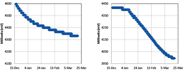
And the result? This script gives me ~700 sensor read cycles per 8mV drop on a 2 AA battery power supply. This is less than half the performance of the SRAM buffering code, which surprised me quite a bit, but I guess that *192 eeprom page writes (with the attendant I2C coms) +1 SD card write per day,  uses 2-3 times as much power as SRAM buffering with 8 SD card write cycles for that same days worth of records. On paper all that eeprom writing represents almost one second per day at 2 mA, which doesn’t seem like much. So either my tiny 128 mb SD cards are very quickly to going back into sleep mode, or keeping the CPU running during all that I2C traffic is using a significant amount of power…?

So what did I learn:  Well knowing that a fair bit of I²C & eeprom traffic will more than double the power drain is quite handy, as I now jump into connecting temperature, pressure, compass, and perhaps other sensors, to those same I2C lines. It will be interesting to see what the real world performance of these loggers is when the rubber meets the…ummm…cave diver.

Addendum 2015-04-18

I simply let the wires I am already using to tap the cascade port I2C lines poke up enough to give me solder points for the EEprom. Don't forget to remove the pullups on the EEprom board.

I simply let the wires I am already using to tap the cascade port I²C lines poke up enough to give me solder points for the EEprom. Don’t forget to remove the pullups on the EEprom board as you already have pullups on the RTC breakout.

The AT24c32 chip can only hold 4k of data –  if you write beyond 4096 bytes, it rewrites over the old data!  So once you have done 128 page writes, you need to flush to the sd card. In this code, I write two 32-byte pages per record. So I have a upper limit of 64 records before I hit that block limit and start to overwrite the data!  I could bump it up to 32k of external eeprom for only $1.50, so I will have to try a few experiments to see if that helps. That 32k eeprom is a code compatible, drop in replacement. All you have to do is change the I2C address for the eeprom for the new board.

Addendum 2014-07-16

The Code below has been posted to the projects GitHub. Look around as the more recent codebuilds are much more elegant than this crude early version, and include sensor support for an easy to build logger.

//Date, Time and Alarm functions using a DS3231 RTC connected via I2C and Wire lib by https://github.com/MrAlvin/RTClib 

// based largely on Jean-Claude Wippler from JeeLab’s excellent RTC library https://github.com/jcw
// clear alarm interupt from http://forum.arduino.cc/index.php?topic=109062.0
// get temp from http://forum.arduino.cc/index.php/topic,22301.0.html
// BMA250_I2C_Sketch.pde -BMA250 Accelerometer using I2C from http://www.dsscircuits.com/accelerometer-bma250.html
// internal Vcc reading trick //forum.arduino.cc/index.php/topic,15629.0.html
// and http://forum.arduino.cc/index.php?topic=88935.0
// free ram code trick: http://learn.adafruit.com/memories-of-an-arduino/measuring-free-memory
// power saving during sleep from http://www.gammon.com.au/forum/?id=11497
// I2C routine based on http://playground.arduino.cc/Code/I2CEEPROM#.UwrbpPldUyI
// New file name routine from http://forums.adafruit.com/viewtopic.php?f=31&t=17964

#include <Wire.h> // 128 byte Serial buffer
#include <SPI.h> // not used here, but needed to prevent a RTClib compile error
#include <avr/sleep.h>
#include <RTClib.h>
#include <PString.h>
#include <SdFat.h>
SdFat sd; // Create the objects to talk to the SD card
SdFile file;
const byte chipSelect = 10; //sd card chip select

#define SampleInterval 1 // power-down time in minutes before interupt triggers the next sample
#define SamplesPerCycle 5 // # of sample cycles to buffer in eeprom before writing to the sd card: MAX of 64! (do not exceed 128 page writes or data will be lost)
unsigned int countLogs = 0; // how many records written to each file
unsigned int fileInterval = 10; // #of log records before new logfile is made
/* count each time a log is written into each file. Must be less than 65,535
counts per file. If the sampleinterval is 15min, and fileInterval is 2880
seconds, then 96samples/day * 30days/month = 30 day intervals */

#define ECHO_TO_SERIAL // echo data that we are logging to the serial monitor
// if you don’t want to echo the data to serial, comment out the above define
#ifdef ECHO_TO_SERIAL
//#define WAIT_TO_START
/* Wait for serial input in setup(), only if serial is enabled. You don’t want
to define WAIT_TO_START unless ECHO_TO_SERIAL is defined, because it would
wait forever to start if you aren’t using the serial monitor.
If you want echo to serial, but not wait to start,
just comment out the above define */
#endif

char FileName[] = “LOG00000.CSV”; //the first file name

#ifndef cbi //defs for stopping the ADC during sleep mode
#define cbi(sfr, bit) (_SFR_BYTE(sfr) &= ~_BV(bit))
#endif
#ifndef sbi
#define sbi(sfr, bit) (_SFR_BYTE(sfr) |= _BV(bit))
#endif

#define DS3231_I2C_ADDRESS 104 //for the RTC temp reading function
#define EEPROM_ADDR 0x57 // I2C Buss address of AT24C32 32K EEPROM
#define EEPromPageSize 32 //32 bytes for the AT24c32 I am using

#define BMA250 0x18
#define BW 0x08 //7.81Hz bandwith
#define GSEL 0x03 // set range 0x03=2g, 0x05=4, 0x08=8g, 0x0C=16g

//I2C eeprom variables
unsigned int CurrentPageStartAddress = 0; //set to zero at the start of each cycle
char EEPROMBuffer[28]; //this buffer contains a string of ascii
//char EEPROMinBuffer[28]; // this buffer recieves numbers from the eeprom was an unsigned char
//note the data read from the eeprom is binary – not ascii characters!

RTC_DS3231 RTC;
byte Alarmhour = 1;
byte Alarmminute = 1;
byte dummyRegister;
byte INTERRUPT_PIN = 2;
volatile boolean clockInterrupt = false;
byte tMSB, tLSB; //for the RTC temp reading function
float RTCTempfloat;
char CycleTimeStamp[ ]= “0000/00/00,00:00:00”;
byte Cycle=0;

//variables for accellerometer reading
uint8_t dataArray[16];
int8_t BMAtemp;
float BMAtempfloat;
uint8_t wholeBMAtemp,fracBMAtemp;
int x,y,z; //acc readings range to negative values

int temp3231;
uint8_t wRTCtemp,fRTCtemp; //components for holding RTC temp as whole and fraction component integers
int Vcc;//the supply voltage via 1.1 internal band gap
byte ledpin = 13; //led indicator pin not used in this code
// the LED on pin 13 is also shared with the SPI SCLK clock, which is used by the microSD card TinyShield.
// So when you use a SPI device like the SD card, the LED will blink, and the SD library will override the digitalWrite() function call.
// If you need a LED for indication, you’ll need to hook up an external one to a different I/O pin.

void setup () {

pinMode(INTERRUPT_PIN, INPUT);
digitalWrite(INTERRUPT_PIN, HIGH);//pull up the interrupt pin
pinMode(13, OUTPUT); // initialize the LED pin as an output.

Serial.begin(9600);
Wire.begin();
RTC.begin();
clearClockTrigger(); //stops RTC from holding the interrupt low if system reset
// time for next alarm
RTC.turnOffAlarm(1);

#ifdef WAIT_TO_START // only triggered if WAIT_TO_START is defined at beging of code
Serial.println(F(“Type any character to start”));
while (!Serial.available());
#endif

delay(1000); //delay to prevent power stutters from writing header to the sd card
DateTime now = RTC.now();

DateTime compiled = DateTime(__DATE__, __TIME__);
if (now.unixtime() < compiled.unixtime()) { //checks if the RTC is not set yet
Serial.println(F(“RTC is older than compile time! Updating”));
// following line sets the RTC to the date & time this sketch was compiled
RTC.adjust(DateTime(__DATE__, __TIME__));
}

initializeBMA(); //initialize the accelerometer – do I have to do this on every wake cycle?

//get the SD card ready
pinMode(chipSelect, OUTPUT); //make sure that the default chip select pin is set to output, even if you don’t use it

#ifdef ECHO_TO_SERIAL
Serial.print(F(“Initializing SD card…”));
#endif

// Initialize SdFat or print a detailed error message and halt
// Use half speed like the native library. // change to SPI_FULL_SPEED for more performance.
if (!sd.begin(chipSelect, SPI_HALF_SPEED)) {
Serial.println(F(“Cound not Initialize Sd Card”));
error(“0”);}

#ifdef ECHO_TO_SERIAL
Serial.println(F(“card initialized.”));
Serial.print(F(“The sample interval for this series is: “));Serial.print(SampleInterval);Serial.println(F(” minutes”));
Serial.println(F(“Timestamp Y/M/D, HH:MM:SS,Time offset, Vcc = , X = , Y = , Z = , BMATemp (C) , RTC temp (C)”));
#endif

// open the file for write at end like the Native SD library
// O_CREAT – create the file if it does not exist
if (!file.open(FileName, O_RDWR | O_CREAT | O_AT_END)) {
Serial.println(F(“1st open LOG.CSV fail”));
error(“1”);
}

file.print(F(“The sample interval for this series is: “));file.print(SampleInterval);file.println(F(” minutes”));
file.println(F(“YYYY/MM/DD HH:MM:SS, Vcc(mV), X = , Y = , Z = , BMATemp (C) , RTC temp (C)”));
file.close();

digitalWrite(13, LOW);
}

void loop () {

// keep track of how many lines have been written to a file
// after so many lines, start a new file
if(countLogs >= fileInterval){
countLogs = 0; // reset our counter to zero
createLogFile(); // create a new file
}

CurrentPageStartAddress = 0;

for (int Cycle = 0; Cycle < SamplesPerCycle; Cycle++) { //this counts from 0 to (SamplesPerCycle-1)

if (clockInterrupt) {
clearClockTrigger();
}

read3AxisAcceleration(); //loads up the Acc data
DateTime now = RTC.now(); // Read the time and date from the RTC

sprintf(CycleTimeStamp, “%04d/%02d/%02d %02d:%02d:%02d”, now.year(), now.month(), now.day(), now.hour(), now.minute(), now.second());

wholeBMAtemp = (int)BMAtempfloat; fracBMAtemp= (BMAtempfloat – wholeBMAtemp) * 100; // Float split into 2 intergers
//can use sprintf(BMATempHolder, “%2d.%2d”, wholeBMAtemp[Cycle], fracBMAtemp[Cycle]) if we need to recompose that float
RTCTempfloat= get3231Temp(); wRTCtemp = (int)RTCTempfloat; fRTCtemp= (RTCTempfloat – wRTCtemp) * 100; // Float split into 2 intergers
Vcc = (readVcc());
if (Vcc < 2800){Serial.println(F(“Voltage too LOW”));error (“L”);}

//serial output for debugging – comment out ECHO_TO_SERIAL to eliminate
#ifdef ECHO_TO_SERIAL
Serial.print(CycleTimeStamp); Serial.print(F(” Cycle “)); Serial.print(Cycle);Serial.print(F(“,”)); Serial.print(Vcc); Serial.print(F(“,”));
Serial.print(x); Serial.print(F(“,”));Serial.print(y); Serial.print(F(“,”)); ;Serial.print(z); Serial.print(F(“,”));
Serial.print(wholeBMAtemp);Serial.print(F(“.”));Serial.print(fracBMAtemp);Serial.print(F(“,”));
Serial.print(wRTCtemp);Serial.print(F(“.”));Serial.print(fRTCtemp);
Serial.print(F(“, Ram:”));Serial.print(freeRam());
delay(40); //short delay to clear com lines
#endif

//Construct first char string of 28 bytes – end of buffer is filled with blank spaces flexibly with pstring
//but could contruct the buffer with sprintf if I wasn’t changing my sensors so often!

PString str(EEPROMBuffer, sizeof(EEPROMBuffer));
str = CycleTimeStamp;str.print(F(“,”));str.print(Vcc);str.print(F(” “));

Write_i2c_eeprom_page(EEPROM_ADDR, CurrentPageStartAddress, EEPROMBuffer); // whole page is written at once here
CurrentPageStartAddress += EEPromPageSize;

//Construct second char string of 28 bytes to complete the record
str = “,”; str.print(x);str.print(F(“,”));str.print(y);str.print(F(“,”));str.print(z);str.print(F(“,”));
str.print(wholeBMAtemp);str.print(F(“.”));str.print(fracBMAtemp);str.print(F(“,”));
str.print(wRTCtemp);str.print(F(“.”));str.print(fRTCtemp);str.print(F(“,”));str.print(F(” “));

Write_i2c_eeprom_page(EEPROM_ADDR, CurrentPageStartAddress, EEPROMBuffer); // 28 bytes/page is max whole page is written at once here
CurrentPageStartAddress += EEPromPageSize;

// IF full set of sample cycles is complete, run a loop to dump data to the sd card
// BUT only if Vcc is above 2.85 volts so we have enough juice!
if (Cycle==(SamplesPerCycle-1) && Vcc >= 2850){

#ifdef ECHO_TO_SERIAL
Serial.print(F(” –Writing to SDcard –“)); delay (10);// this line for debugging only
#endif

CurrentPageStartAddress=0; //reset the page counter back to the beginning

file.open(FileName, O_RDWR | O_AT_END);
// open the file for write at end like the Native SD library
//if (!file.open(FileName, O_RDWR | O_AT_END)) {
// error(“L open file fail”);
//}

for (int i = 0; i < SamplesPerCycle; i++) { //loop to read from I2C ee and write to SD card

Read_i2c_eeprom_page(EEPROM_ADDR, CurrentPageStartAddress, EEPROMBuffer, sizeof(EEPROMBuffer) ); //there will be a few blank spaces
CurrentPageStartAddress += EEPromPageSize;
file.write(EEPROMBuffer,sizeof(EEPROMBuffer));

Read_i2c_eeprom_page(EEPROM_ADDR, CurrentPageStartAddress, EEPROMBuffer, sizeof(EEPROMBuffer) );
CurrentPageStartAddress += EEPromPageSize;
file.write(EEPROMBuffer,sizeof(EEPROMBuffer));
file.println(F(” “));

countLogs++;
// An application which writes to a file using print(), println() or write() must call sync()
// at the appropriate time to force data and directory information to be written to the SD Card.
// every 8 cycles we have dumped approximately 512 bytes to the card
// note only going to buffer 96 cycles to eeprom (one day at 15 min samples)
if(i==8){syncTheFile;}
if(i==16){syncTheFile;}
if(i==24){syncTheFile;}
if(i==32){syncTheFile;}
if(i==40){syncTheFile;}
if(i==48){syncTheFile;}
if(i==56){syncTheFile;}
if(i==64){syncTheFile;}
if(i==72){syncTheFile;}
if(i==80){syncTheFile;}
if(i==88){syncTheFile;}
}
file.close();
}
// setNextAlarmTime();
Alarmhour = now.hour(); Alarmminute = now.minute()+SampleInterval;
if (Alarmminute > 59) { //error catch – if alarmminute=60 the interrupt never triggers due to rollover!
Alarmminute =0; Alarmhour = Alarmhour+1; if (Alarmhour > 23) {Alarmhour =0;}
}
RTC.setAlarm1Simple(Alarmhour, Alarmminute);
RTC.turnOnAlarm(1);

#ifdef ECHO_TO_SERIAL
Serial.print(F(” Alarm Set:”)); Serial.print(now.hour(), DEC); Serial.print(‘:’); Serial.print(now.minute(), DEC);
Serial.print(F(” Sleep:”)); Serial.print(SampleInterval);Serial.println(F(” min.”));
delay(100); //a delay long enought to boot out the serial coms
#endif

sleepNow(); //the sleep call is inside the main cycle counter loop

} //samples per cycle loop terminator
} //the main void loop terminator

void createLogFile(void) {
// create a new file, up to 100,000 files allowed
// we will create a new file every time this routine is called
// If we are creating another file after fileInterval, then we must
// close the open file first.
if (file.isOpen()) {
file.close();
}
for (uint16_t i = 0; i < 100000; i++) {
FileName[3] = i/10000 + ‘0’;
FileName[4] = i/1000 + ‘0’;
FileName[5] = i/100 + ‘0’;
FileName[6] = i/10 + ‘0’;
FileName[7] = i%10 + ‘0’;
// O_CREAT – create the file if it does not exist
// O_EXCL – fail if the file exists O_WRITE – open for write
if (file.open(FileName, O_CREAT | O_EXCL | O_WRITE)) break;
//if you can open a file with the new name, break out of the loop
}

// clear the writeError flags generated when we broke the new name loop
file.writeError = 0;

if (!file.isOpen()) error (“diskful?”);
Serial.print(F(“Logging to: “));
Serial.println(FileName);

// fetch the time
DateTime now = RTC.now();
// set creation date time
if (!file.timestamp(T_CREATE,now.year(),now.month(),now.day(),now.hour(),
now.minute(),now.second() )) {
error(“cr t”);
}
// set write/modification date time
if (!file.timestamp(T_WRITE,now.year(),now.month(),now.day(),now.hour(),
now.minute(),now.second() )) {
error(“wr t”);
}
// set access date
if (!file.timestamp(T_ACCESS,now.year(),now.month(),now.day(),now.hour(),
now.minute(),now.second() )) {
error(“ac t”);
}
file.sync();
//file.close();
//file.open(FileName, O_RDWR | O_AT_END);

// write the file as a header:
file.print(F(“The sample interval for this series is:”)); ;Serial.print(SampleInterval);Serial.println(F(” minutes”));
file.println(F(“YYYY/MM/DD HH:MM:SS, Vcc(mV), X = , Y = , Z = , BMATemp (C) , RTC temp (C)”));
file.close();

#ifdef ECHO_TO_SERIAL
Serial.println(F(“New log file created on the SD card!”));
#endif // ECHO_TO_SERIAL

// write out the header to the file, only upon creating a new file
if (file.writeError) {
// check if error writing
error(“write header”);
}

// if (!file.sync()) {
// check if error writing
// error(“fsync er”);
// }

}
void syncTheFile(void) {
/* don’t sync too often – requires 2048 bytes of I/O to SD card.
512 bytes of I/O if using Fat16 library */
/* blink LED to show we are syncing data to the card & updating FAT!
but cant use LED on pin 13, because chipselect */
// digitalWrite(LEDpin, HIGH);
if (!file.sync()) { error(“sync error”);}
// digitalWrite(greenLEDpin, LOW);
}

// Address is a page address
// But data can be maximum of 28 bytes, because the Wire library has a buffer of 32 bytes
void Write_i2c_eeprom_page( int deviceaddress, unsigned int eeaddress, char* data) {
unsigned char i=0;
unsigned int address;
address=eeaddress;
Wire.beginTransmission(deviceaddress);
Wire.write((int)((address) >> 8)); // MSB
Wire.write((int)((address) & 0xFF)); // LSB
do{
Wire.write((byte) data[i]);i++;
} while(data[i]);
Wire.endTransmission();
delay(10); // data sheet says 5ms for page write
}

// should not read more than 28 bytes at a time!
void Read_i2c_eeprom_page( int deviceaddress, unsigned int eeaddress,char* data, unsigned int num_chars) {
unsigned char i=0;
Wire.beginTransmission(deviceaddress);
Wire.write((int)(eeaddress >> 8)); // MSB
Wire.write((int)(eeaddress & 0xFF)); // LSB
Wire.endTransmission();
Wire.requestFrom(deviceaddress,(num_chars-1));
while(Wire.available()) data[i++] = Wire.read();
}

void sleepNow() {
// can set the unused digital pins to output low – BUT only worth 1-2 µA during sleep
// if you have an LED or something like that on an output pin, you will draw more current.
// for (byte i = 0; i <= number of digital pins; i++)
// {
// pinMode (i, OUTPUT);
// digitalWrite (i, LOW);
// }

cbi(ADCSRA,ADEN); // Switch ADC OFF: worth 334 µA during sleep
set_sleep_mode(SLEEP_MODE_PWR_DOWN);
sleep_enable();
attachInterrupt(0,clockTrigger, LOW);
// turn off brown-out enable in software: worth 25 µA during sleep
// BODS must be set to one and BODSE must be set to zero within four clock cycles
// BUT http://learn.adafruit.com/low-power-coin-cell-voltage-logger/other-lessons
// MCUCR = bit (BODS) | bit (BODSE); // turn on brown-out enable select
// MCUCR = bit (BODS); // The BODS bit is automatically cleared after three clock cycles
sleep_mode();
//HERE AFTER WAKING UP
sleep_disable();
detachInterrupt(0);
sbi(ADCSRA,ADEN); // Switch ADC converter back ON
//digitalWrite(13, HIGH); this doesnt work because of conflict with sd card chip select
}

void clockTrigger() {
clockInterrupt = true; //do something quick, flip a flag, and handle in loop();
}

void clearClockTrigger()
{
Wire.beginTransmission(0x68); //Tell devices on the bus we are talking to the DS3231
Wire.write(0x0F); //Tell the device which address we want to read or write
Wire.endTransmission(); //Before you can write to and clear the alarm flag you have to read the flag first!
Wire.requestFrom(0x68,1); // Read one byte
dummyRegister=Wire.read(); // In this example we are not interest in actually using the bye
Wire.beginTransmission(0x68); //Tell devices on the bus we are talking to the DS3231
Wire.write(0x0F); //Tell the device which address we want to read or write
Wire.write(0b00000000); //Write the byte. The last 0 bit resets Alarm 1
Wire.endTransmission();
clockInterrupt=false; //Finally clear the flag we use to indicate the trigger occurred
}

// could also use RTC.getTemperature() from the library here as in:
// RTC.convertTemperature(); //convert current temperature into registers
// Serial.print(RTC.getTemperature()); //read registers and display the temperature

float get3231Temp()
{
//temp registers (11h-12h) get updated automatically every 64s
Wire.beginTransmission(DS3231_I2C_ADDRESS);
Wire.write(0x11);
Wire.endTransmission();
Wire.requestFrom(DS3231_I2C_ADDRESS, 2);

if(Wire.available()) {
tMSB = Wire.read(); //2’s complement int portion
tLSB = Wire.read(); //fraction portion

temp3231 = ((((short)tMSB << 8 | (short)tLSB) >> 6) / 4.0);
// Allows for readings below freezing – Thanks to Coding Badly
//temp3231 = (temp3231 * 1.8 + 32.0); // Convert Celcius to Fahrenheit
return temp3231;

}
else {
temp3231 = 255.0; //Use a value of 255 as error flag
}

return temp3231;
}
byte read3AxisAcceleration()
{
Wire.beginTransmission(BMA250);
Wire.write(0x02);
Wire.endTransmission();
Wire.requestFrom(BMA250,7);
for(int j = 0; j < 7;j++)
{
dataArray[j] = Wire.read();
}
if(!bitRead(dataArray[0],0)){return(0);}

BMAtemp = dataArray[6];
x = dataArray[1] << 8;
x |= dataArray[0];
x >>= 6;
y = dataArray[3] << 8;
y |= dataArray[2];
y >>= 6;
z = dataArray[5] << 8;
z |= dataArray[4];
z >>= 6;

BMAtempfloat = (BMAtemp*0.5)+24.0;
}
byte initializeBMA()
{
Wire.beginTransmission(BMA250);
Wire.write(0x0F); //set g
Wire.write(GSEL);
Wire.endTransmission();
Wire.beginTransmission(BMA250);
Wire.write(0x10); //set bandwith
Wire.write(BW);
Wire.endTransmission();
return(0);
}

long readVcc() { //trick to read the Vin using internal 1.1 v as a refrence
long result;
// Read 1.1V reference against AVcc
ADMUX = _BV(REFS0) | _BV(MUX3) | _BV(MUX2) | _BV(MUX1);
delay(3); // Wait for Vref to settle
ADCSRA |= _BV(ADSC); // Convert
while (bit_is_set(ADCSRA,ADSC));
result = ADCL;
result |= ADCH<<8;
result = 1126400L / result; // Back-calculate AVcc in mV
return result;
}

int freeRam () {
extern int __heap_start, *__brkval;
int v;
return (int) &v – (__brkval == 0 ? (int) &__heap_start : (int) __brkval);
}

void error(char *str) {
// always write error messages to the serial monitor but this routine wastes
// everything passed to the string from the original call is in sram!
Serial.print(F(“error in: “));Serial.println(str);
/* this next statement will start an endless loop, basically stopping all
operation upon any error. Change this behavior if you want. */
while (1);
}

Updated SRAM buffering data logger code.

I de-soldered the power led, and removed the Bat charging circuit from the RTC board

I de-soldered the power led, and removed the battery charging circuit from the RTC board.

Before I post the results of the eeprom buffering experiment, I will just add the updated version of the code that buffers 12 sensor read cycles of data in the internal SRAM before writing to a small 128mb Sandisk SD card.  In my power drain tests, using 2xAA batteries as the power supply, this code was completing ~1700 accelerometer/RTC read cycles per 8mv drop on the power supply! If I take a sample every 15 minutes, this projects out to a core data logger unit that uses power on par with the natural self-discharge rate of the batteries!

Updates from the last version:
This script automatically creates new data files at an interval determined by comparing the fileInterval to the countlog (thanks adafruit!) There is also a nice #ifdef …#endif trick to control echoing to serial by simply commenting out the ECHO_TO_SERIAL def at the beginning of the code. And finally an error subroutine, which hangs the system in a while(1); if something goes wrong. I use somewhat cryptic error codes, as every character passed to the error routine eats into my precious SRAM budget.

The current data output looks like this on the SD card:

The sample interval for this series is: 1 minute
MM/DD/YY HH:MM:SS Cycle# = Toffset ,Vcc(mV), X = Y = Z = ,BMATemp, RTCtemp
2/27/2014 13:53 time offset: 0   2972   10  -5 228   28     25
2/27/2014 13:53 time offset: 1   2964      9  -5 227   27.5  25
2/27/2014 13:53 time offset: 2   2964      9  -4 227   27.5  24
2/27/2014 13:53 time offset: 3   2964      8  -3 227   26.5  24
2/27/2014 13:53 time offset: 4   2964      9  -4 227   26     24
2/27/2014 13:53 time offset: 5   2964      9  -4 228   26     24
2/27/2014 13:53 time offset: 6   2964    10  -3 228   26.5  24
2/27/2014 13:53 time offset: 7   2964    10  -4 228   25.5  24
2/27/2014 13:53 time offset: 8   2964    10  -4 228   25.5  24
2/27/2014 13:53 time offset: 9   2964      9  -4 228   25.5  24
2/27/2014 13:53 time offset: 10 2964    10  -4 227   25.5  24
2/27/2014 13:53 time offset: 11 2964     10  -4 228   25.5  24
2/27/2014 14:05 time offset: 0  2964        8 -3 228    25.5  24
…etc
(Note: Excel switched to d/m/y here! I always use Y/M/D!)

Only one time stamp is recorded per 12 cycles, as that’s just too many characters to buffer in the limited SRAM (no unix time yet!). So I will have to re-constitute the full time stamp in post. If you use this code, keep a very close eye on the freemem, as you sensors will generate different data, and every single byte/character you are buffering to SRAM matters. My system gets wobbly whenever the freemem goes down near 550…

Addendum: The code shown below has been posted to the projects GitHub. You can now download it HERE.

// Date, Time and Alarm functions using a DS3231 RTC connected via I2C and Wire lib by https://github.com/MrAlvin/RTClib
// based largely on Jean-Claude Wippler from JeeLab’s excellent RTC library https://github.com/jcw
// clear alarm interupt from http://forum.arduino.cc/index.php?topic=109062.0
// get temp from http://forum.arduino.cc/index.php/topic,22301.0.html which does not use the RTCLIB!
// BMA250_I2C_Sketch.pde -BMA250 Accelerometer using I2C from http://www.dsscircuits.com/accelerometer-bma250.html
// combined with internal voltage reading trick //forum.arduino.cc/index.php/topic,15629.0.html
// floats to string conversion: http://dereenigne.org/arduino/arduino-float-to-string

// free ram code trick: http://learn.adafruit.com/memories-of-an-arduino/measuring-free-memory
// power saving during sleep from http://www.gammon.com.au/forum/?id=11497

// new name routine from https://github.com/adafruit/Light-and-Temp-logger
// about 12 bytes per data cycle! 681 freeram with 10 cycles!

#include <SD.h> //a memory hog – takes 512 bytes of ram just to run!
#include <Wire.h>
#include <SPI.h> // not used here, but needed to prevent a RTClib compile error
#include <avr/sleep.h>
#include <RTClib.h>

#ifndef cbi //defs for stopping the ADC during sleep mode
#define cbi(sfr, bit) (_SFR_BYTE(sfr) &= ~_BV(bit))
#endif
#ifndef sbi
#define sbi(sfr, bit) (_SFR_BYTE(sfr) |= _BV(bit))
#endif

#define DS3231_I2C_ADDRESS 104 //for the RTC temp reading function

#define BMA250 0x18
#define BW 0x08 //7.81Hz bandwith
#define GSEL 0x03 // set range 0x03 – 2g, 0x05 – 4, 0x08 – 8g, 0x0C – 16g

#define SampleInterval 1 // power-down time in minutes before interupt triggers the next sample
#define SamplesPerCycle 12 //# of sample cycles before writing to the sd card
unsigned int countLogs = 0; // how many records written to each file
unsigned int fileInterval = 96; // #of log records before new logfile is made
/* count each time a log is written into each file. Must be less than 65,535
counts per file. If the sampleinterval is 15min, and fileInterval is 2880
seconds, then 96samples/day * 30days/month = 30 day intervals */

//#define ECHO_TO_SERIAL // echo data that we are logging to the serial monitor
// if you don’t want to echo the data to serial, comment out the above define
#ifdef ECHO_TO_SERIAL
//#define WAIT_TO_START
/* Wait for serial input in setup(), only if serial is enabled. You don’t want
to define WAIT_TO_START unless ECHO_TO_SERIAL is defined, because it would
wait forever to start if you aren’t using the serial monitor.
If you want echo to serial, but not wait to start,
just comment out the above define */
#endif

File logfile;
char filename[] = “LOGGER00.CSV”; //the first file name

RTC_DS3231 RTC;
byte Alarmhour = 1;
byte Alarmminute = 1;
byte dummyRegister;
byte INTERRUPT_PIN = 2;
volatile boolean clockInterrupt = false;
byte tMSB, tLSB; //for the RTC temp reading function
float RTCTempfloat;
char CycleTimeStamp[ ]= “0000/00/00,00:00:00”;
byte Cycle=0;

const byte chipSelect = 10; //sd card chip select

uint8_t dataArray[16]; //variables for accellerometer reading
int8_t BMAtemp; //why does the bma temp read out as an interger? Temp is in units of 0.5 degrees C
//8 bits given in two’s complement representation
float BMAtempfloat;//float BMATempHolder;
//char BMATempHolder[ ]= “00.00”;
//components for holding bma temp as two intergers – we have no negative temps in our application
uint8_t wholeBMAtemp[SamplesPerCycle],fracBMAtemp[SamplesPerCycle];

int x,y,z; //these guys range to negative values
int xAcc[SamplesPerCycle],yAcc[SamplesPerCycle],zAcc[SamplesPerCycle];

uint8_t wRTCtemp[SamplesPerCycle],fRTCtemp[SamplesPerCycle]; //components for holding RTC temp as two intergers
int temp3231;
int Vcc[SamplesPerCycle];//the supply voltage via 1.1 internal band gap

byte ledpin = 13; //led indicator pin not used in this code

void setup () {

pinMode(INTERRUPT_PIN, INPUT);
digitalWrite(INTERRUPT_PIN, HIGH);//pull up the interrupt pin
pinMode(13, OUTPUT); // initialize the LED pin as an output.
digitalWrite(13, HIGH); // turn the LED on to warn against SD card removal does this work?

Serial.begin(9600);
Wire.begin();
RTC.begin();
clearClockTrigger(); //stops RTC from holding the interrupt low if system reset
// time for next alarm
RTC.turnOffAlarm(1);

#ifdef WAIT_TO_START // only triggered if WAIT_TO_START is defined at beging of code
Serial.println(F(“Type any character to start”));
while (!Serial.available());
#endif

DateTime now = RTC.now();
DateTime compiled = DateTime(__DATE__, __TIME__);
if (now.unixtime() < compiled.unixtime()) {
Serial.println(F(“RTC is older than compile time! Updating”));
// following line sets the RTC to the date & time this sketch was compiled
RTC.adjust(DateTime(__DATE__, __TIME__));
}

Alarmhour = now.hour();
Alarmminute = now.minute()+ SampleInterval ;
if (Alarmminute > 59) { //error catch – if Alarmminute=60 the interrupt never triggers due to rollover
Alarmminute = 0; Alarmhour = Alarmhour+1; if (Alarmhour > 23) {Alarmhour =0;}
}

initializeBMA(); //initialize the accelerometer – do I have to do this on every wake cycle?

delay(1000); //delay to prevent power stutters from writing header to the sd card

//get the SD card ready
pinMode(chipSelect, OUTPUT); //make sure that the default chip select pin is set to output, even if you don’t use it

// initialize the SD card
Serial.print(“Initializing SD card…”);
// make sure that the default chip select pin is set to
// output, even if you don’t use it:
pinMode(10, OUTPUT);

// see if the card is present and can be initialized:
if (!SD.begin(chipSelect)) {
Serial.println(“Card failed, or not present”);
// don’t do anything more:
return;
}
Serial.println(“card initialized.”);

// create a new file
for (uint8_t i = 0; i < 100; i++) {
filename[6] = i/10 + ‘0’;
filename[7] = i%10 + ‘0’;
if (! SD.exists(filename)) {
// only open a new file if it doesn’t exist
logfile = SD.open(filename, FILE_WRITE);
break; // leave the loop!
}
}

if (! logfile) {
Serial.println(F(“Error creating logger file!”));error(“1”);
}

logfile.print(F(“The sample interval for this series is: “));logfile.print(SampleInterval);logfile.println(F(” minutes”));
logfile.println(F(“DD/MM/YYYY HH:MM:SS, Cycle# = Time offset, Vcc(mV), X = , Y = , Z = , BMATemp (C) , RTC temp (C)”));
logfile.close();

// if (logfile.writeError || !logfile.sync()) {
// Serial.println(F(“Error writing header to logger file!”));error(“2”);
// }

#ifdef ECHO_TO_SERIAL
Serial.print(“Logging to: “);
Serial.println(filename);
Serial.print(F(“The sample interval for this series is: “));Serial.print(SampleInterval);Serial.println(F(” minutes”));
Serial.println(F(“Timestamp Y/M/D, HH:MM:SS,Time offset, Vcc = , X = , Y = , Z = , BMATemp (C) , RTC temp (C)”));
#endif

digitalWrite(13, LOW);
}

void loop () {

// keep track of how many lines have been written to a file
// after so many lines, start a new file
if(countLogs >= fileInterval){

// create a new file
for (uint8_t i = 0; i < 100; i++) {
filename[6] = i/10 + ‘0’;
filename[7] = i%10 + ‘0’;
if (! SD.exists(filename)) {
// only open a new file if it doesn’t exist
logfile = SD.open(filename, FILE_WRITE);
break; // leave the loop!
}
}

if (! logfile) {
Serial.println(F(“Error creating logger file!”));error(“1”);
}

logfile.print(F(“The sample interval for this series is: “));logfile.print(SampleInterval);logfile.println(F(” minutes”));
logfile.println(F(“YYYY/MM/DD HH:MM:SS, Cycle#, = Time offset, Vcc(mV), X = , Y = , Z = , BMATemp (C) , RTC temp (C)”));
logfile.close();

// if (logfile.writeError || !logfile.sync()) {
// Serial.println(F(“Error writing header to logger file!”));error(“2”);
// }

#ifdef ECHO_TO_SERIAL
Serial.print(“Logging to: “);
Serial.println(filename);
Serial.print(F(“The sample interval for this series is: “));Serial.print(SampleInterval);Serial.println(F(” minutes”));
Serial.println(F(“Timestamp D/M/Y, HH:MM:SS,Time offset, Vcc = , X = , Y = , Z = , BMATemp (C) , RTC temp (C)”));
#endif

countLogs = 0; // reset our counter to zero

}

for (int Cycle = 0; Cycle < SamplesPerCycle; Cycle++) { //this counts from 0 to (SamplesPerCycle-1)

if (clockInterrupt) {
clearClockTrigger();
}

read3AxisAcceleration(); //loads up the dataString
DateTime now = RTC.now(); // Read the time and date from the RTC

if(Cycle==0){ //timestamp for each cycle only gets set once
sprintf(CycleTimeStamp, “%04d/%02d/%02d %02d:%02d:%02d”, now.year(), now.month(), now.day(), now.hour(), now.minute(), now.second());
}

xAcc[Cycle]=x;yAcc[Cycle]=y;zAcc[Cycle]=z; //BMAtemp_[Cycle] = BMAtempfloat;
wholeBMAtemp[Cycle] = (int)BMAtempfloat; fracBMAtemp[Cycle]= (BMAtempfloat – wholeBMAtemp[Cycle]) * 100; // Float split into 2 intergers
//can use sprintf(BMATempHolder, “%2d.%2d”, wholeBMAtemp[Cycle], fracBMAtemp[Cycle]) if we need to recompose that float
Vcc[Cycle] = (readVcc());
if (Vcc[Cycle] < 2800){Serial.println(F(“Voltage too LOW”));error (“L”);} //the hangs the system when the voltage is too low.

RTCTempfloat= get3231Temp();
wRTCtemp[Cycle] = (int)RTCTempfloat; fRTCtemp[Cycle]= (RTCTempfloat – wRTCtemp[Cycle]) * 100; // Float split into 2 intergers

//main serial line output loop – which can be commented out for deployment
#ifdef ECHO_TO_SERIAL
Serial.print(CycleTimeStamp); Serial.print(F(” Cycle “)); Serial.print(Cycle);Serial.print(F(“,”)); Serial.print(Vcc[Cycle]); Serial.print(F(“,”));
Serial.print(xAcc[Cycle]); Serial.print(F(“,”));Serial.print(yAcc[Cycle]); Serial.print(F(“,”)); ;Serial.print(zAcc[Cycle]); Serial.print(F(“,”));
Serial.print(wholeBMAtemp[Cycle]);Serial.print(F(“.”));Serial.print(fracBMAtemp[Cycle]);Serial.print(F(“,”));
Serial.print(wRTCtemp[Cycle]);Serial.print(F(“.”));Serial.print(fRTCtemp[Cycle]);
Serial.print(F(“, Ram:”));Serial.print(freeRam());
delay(50); //short delay to clear com lines
#endif

// Once each full set of cycles is complete, dump data to the sd card
// but if Vcc below 2.85 volts, dont write to the sd card
if (Cycle==(SamplesPerCycle-1) && Vcc[Cycle] >= 2850){
Serial.print(F(” –write data –“)); delay (50);// this line for debugging only

File logfile = SD.open(filename, FILE_WRITE);

if (logfile) { // if the file is available, write to it:

for (int i = 0; i < SamplesPerCycle; i++) { //loop to dump out one line of data per cycle
logfile.print(CycleTimeStamp);
logfile.print(F(“,time offset:,”));logfile.print(i);logfile.print(F(“,”));logfile.print(Vcc[i]); logfile.print(F(“,”));
logfile.print(xAcc[i]); logfile.print(F(“,”));logfile.print(yAcc[i]); logfile.print(“,”);logfile.print(zAcc[i]); logfile.print(F(“,”));
logfile.print(wholeBMAtemp[i]);logfile.print(F(“.”));logfile.print(fracBMAtemp[i]);logfile.print(F(“,”));
logfile.print(wRTCtemp[i]);logfile.print(F(“.”));logfile.print(fRTCtemp[i]);logfile.println(F(“,”));
// do I need to add a delay line here for sd card communications? could I buffer this better to save power?
countLogs++;
}
logfile.close();
}
else { //if the file isn’t open, pop up an error:
Serial.println(F(“Error opening datalog.txt file”));
}
}

// setNextAlarmTime();
Alarmhour = now.hour(); Alarmminute = now.minute()+SampleInterval;
if (Alarmminute > 59) { //error catch – if alarmminute=60 the interrupt never triggers due to rollover!
Alarmminute =0; Alarmhour = Alarmhour+1; if (Alarmhour > 23) {Alarmhour =0;}
}
RTC.setAlarm1Simple(Alarmhour, Alarmminute);
RTC.turnOnAlarm(1);

//print lines commented out for deployment
Serial.print(F(” Alarm Set:”)); Serial.print(now.hour(), DEC); Serial.print(‘:’); Serial.print(now.minute(), DEC);
Serial.print(F(” Sleep:”)); Serial.print(SampleInterval);Serial.println(F(” min.”));
delay(100); //a delay long enought to boot out the serial coms

sleepNow(); //the sleep call is inside the main cycle counter loop
}

}

void sleepNow() {
// set the unused digital pins to output low – only worth 1-2 µA during sleep
// if you have an LED or something like that on an output pin, you will draw more current.
// for (byte i = 0; i <= A5; i++)
// {
// pinMode (i, OUTPUT);
// digitalWrite (i, LOW);
// }

cbi(ADCSRA,ADEN); // Switch ADC OFF: worth 334 µA during sleep
set_sleep_mode(SLEEP_MODE_PWR_DOWN);
sleep_enable();
attachInterrupt(0,clockTrigger, LOW);
// turn off brown-out enable in software: worth 25 µA during sleep
// BODS must be set to one and BODSE must be set to zero within four clock cycles
MCUCR = bit (BODS) | bit (BODSE); // turn on brown-out enable select
MCUCR = bit (BODS); // The BODS bit is automatically cleared after three clock cycles
sleep_mode();
//HERE AFTER WAKING UP
sleep_disable();
detachInterrupt(0);
sbi(ADCSRA,ADEN); // Switch ADC converter back ON
//digitalWrite(13, HIGH); this doesnt work because of conflict with sd card chip select
}

void clockTrigger() {
clockInterrupt = true; //do something quick, flip a flag, and handle in loop();
}

void clearClockTrigger()
{
Wire.beginTransmission(0x68); //Tell devices on the bus we are talking to the DS3231
Wire.write(0x0F); //Tell the device which address we want to read or write
Wire.endTransmission(); //Before you can write to and clear the alarm flag you have to read the flag first!
Wire.requestFrom(0x68,1); // Read one byte
dummyRegister=Wire.read(); // In this example we are not interest in actually using the bye
Wire.beginTransmission(0x68); //Tell devices on the bus we are talking to the DS3231
Wire.write(0x0F); //Tell the device which address we want to read or write
Wire.write(0b00000000); //Write the byte. The last 0 bit resets Alarm 1
Wire.endTransmission();
clockInterrupt=false; //Finally clear the flag we use to indicate the trigger occurred
}

// could also use RTC.getTemperature() from the library here as in:
// RTC.convertTemperature(); //convert current temperature into registers
// Serial.print(RTC.getTemperature()); //read registers and display the temperature

float get3231Temp()
{
//temp registers (11h-12h) get updated automatically every 64s
Wire.beginTransmission(DS3231_I2C_ADDRESS);
Wire.write(0x11);
Wire.endTransmission();
Wire.requestFrom(DS3231_I2C_ADDRESS, 2);

if(Wire.available()) {
tMSB = Wire.read(); //2’s complement int portion
tLSB = Wire.read(); //fraction portion

temp3231 = ((((short)tMSB << 8 | (short)tLSB) >> 6) / 4.0); // Allows for readings below freezing – Thanks to Coding Badly
//temp3231 = (temp3231 * 1.8 + 32.0); // Convert Celcius to Fahrenheit
return temp3231;

}
else {
temp3231 = 255.0; //Use a value of 255 to error flag that we did not get temp data from the ds3231
}

return temp3231;
}
byte read3AxisAcceleration()
{
Wire.beginTransmission(BMA250);
Wire.write(0x02);
Wire.endTransmission();
Wire.requestFrom(BMA250,7);
for(int j = 0; j < 7;j++)
{
dataArray[j] = Wire.read();
}
if(!bitRead(dataArray[0],0)){return(0);}

BMAtemp = dataArray[6];
x = dataArray[1] << 8;
x |= dataArray[0];
x >>= 6;
y = dataArray[3] << 8;
y |= dataArray[2];
y >>= 6;
z = dataArray[5] << 8;
z |= dataArray[4];
z >>= 6;

BMAtempfloat = (BMAtemp*0.5)+24.0;
}
byte initializeBMA()
{
Wire.beginTransmission(BMA250);
Wire.write(0x0F); //set g
Wire.write(GSEL);
Wire.endTransmission();
Wire.beginTransmission(BMA250);
Wire.write(0x10); //set bandwith
Wire.write(BW);
Wire.endTransmission();
return(0);
}

long readVcc() { //trick to read the Vin using internal 1.1 v as a refrence
long result;
// Read 1.1V reference against AVcc
ADMUX = _BV(REFS0) | _BV(MUX3) | _BV(MUX2) | _BV(MUX1);
delay(3); // Wait for Vref to settle
ADCSRA |= _BV(ADSC); // Convert
while (bit_is_set(ADCSRA,ADSC));
result = ADCL;
result |= ADCH<<8;
result = 1126400L / result; // Back-calculate AVcc in mV
return result;
}

int freeRam () {
extern int __heap_start, *__brkval;
int v;
return (int) &v – (__brkval == 0 ? (int) &__heap_start : (int) __brkval);
}

void error(char *str) {
// always write error messages to the serial monitor but this routine wastes
// everything passed to the string from the original call is in sram!
Serial.print(F(“error in: “));Serial.println(str);
/* this next statement will start an endless loop, basically stopping all
operation upon any error. Change this behavior if you want. */
// red LED indicates error
//digitalWrite(redLEDpin, HIGH);
while (1);
}

Leaner meaner code for the Cave Pearls.

The new terminal block protoshield makes the RTC hookup easy!

The new  TinyDuino terminal block protoshield makes the RTC hookup easy!

I have spent some time making that rough code more efficient, so that I can buffer more sensor read cycles to the Arduino’s very limited SRAM before having to burn away battery power writing data to the SD cards. There were several great references out there to guide me, and a few helpful people took time to email me suggestions, some of which have been implemented here:

Eliminate unnecessary cruft:

I stopped dumping all the data into a text string, which got rid of the commas, spaces, etc that I had been buffering for nothing. I guess this is a pretty common newbie mistake.

And instead of buffering the entire date & time stamp, I simply record it once at the beginning of a sample cycle and then use a one byte record/offset number, as I can re-calculate the actual time for each sample from this offset number. This saved a huge amount of free ram! (Thanks Mike!)

Use the smallest variable types possible.

I converted the floating point temperature readings into sets of two integers (the part before the decimal place, and the part after the decimal place) and any integers that were storing values less than 256, are now bytes, or uint8_t, which cut them down by half. The single time stamp per cycle is now stored in a well defined “char” variable. One person suggested that with some fancy bit management I could probably cut those variables in half again, but I have not quite wrapped my head around bit shifting & two’s complement yet. (Thanks Ken!)

Write better code:

The crude code duplication of the earlier versions has been replaced with array variables and for loops, which you control via the SampleInterval and SamplesPerCycle defines at the beginning of the script. These cascade through to the array definitions. I should mention here that I tried this approach before when I had the data packed into strings and it simply did not work. The freeRam routine showed me that every cycle bled away another byte or two till the system crashed. But AFTER I got rid of all the strings in the script, the loops are stable. I suspect there is a bug in the way the AVR compiler handles string data.

The net result of these changes is that each record went from about 60 characters down to 12 bytes of data, so this script can easily buffer 10 cycles or more of data and still leave 680 bytes of free ram. A nice safe margin away from the 512 bytes that I have to leave available for the SD.h buffer.

I expect to sample the sensors between 50-100 times per day, but for power management, I only want to write to the SD card once per day. So now I need to look at a second level of buffering, with eeprom memory…

// Date, Time and Alarm functions using a DS3231 RTC connected via I2C and Wire lib by https://github.com/MrAlvin/RTClib
// based largely on Jean-Claude Wippler from JeeLab’s excellent RTC library https://github.com/jcw
// clear alarm interupt from http://forum.arduino.cc/index.php?topic=109062.0
// get temp from http://forum.arduino.cc/index.php/topic,22301.0.html which does not use the RTCLIB!
// BMA250_I2C_Sketch.pde -BMA250 Accelerometer using I2C from http://www.dsscircuits.com/accelerometer-bma250.html
// combined with internal voltage reading trick //forum.arduino.cc/index.php/topic,15629.0.html
// floats to string conversion: http://dereenigne.org/arduino/arduino-float-to-string// free ram code trick: http://learn.adafruit.com/memories-of-an-arduino/measuring-free-memory
// power saving during sleep from http://www.gammon.com.au/forum/?id=11497

#include <SD.h> //a memory hog – takes 512 bytes of ram just to run!
#include <Wire.h>
#include <SPI.h> // not used here, but needed to prevent a RTClib compile error
#include <avr/sleep.h>
#include <RTClib.h>

#ifndef cbi //defs for stopping the ADC during sleep mode
#define cbi(sfr, bit) (_SFR_BYTE(sfr) &= ~_BV(bit))
#endif
#ifndef sbi
#define sbi(sfr, bit) (_SFR_BYTE(sfr) |= _BV(bit))
#endif

#define DS3231_I2C_ADDRESS 104 //for the RTC temp reading function

#define BMA250 0x18
#define BW 0x08 //7.81Hz bandwith
#define GSEL 0x03 // set range 0x03 – 2g, 0x05 – 4, 0x08 – 8g, 0x0C – 16g

#define SampleInterval 1
// power-down time in minutes before interupt triggers the next sample

#define SamplesPerCycle 10
//# of sample cycles before writing to the sd card

RTC_DS3231 RTC;
byte Alarmhour = 1;
byte Alarmminute = 1;
byte dummyRegister;
byte INTERRUPT_PIN = 2;
volatile boolean clockInterrupt = false;
byte tMSB, tLSB; //for the RTC temp reading function
float RTCTempfloat;
char CycleTimeStamp[ ]= “0000/00/00,00:00:00”;
byte Cycle=0;

const byte chipSelect = 10; //sd card chip select

uint8_t dataArray[16]; //variables for accellerometer reading
int8_t BMAtemp; //Temp is in units of 0.5 degrees C
//8 bits given in two’s complement representation
float BMAtempfloat;//float BMATempHolder;
//char BMATempHolder[ ]= “00.00”;
//components for holding BMA250 temp as two integers – we have no negative temps in our application
uint8_t wholeBMAtemp[SamplesPerCycle],fracBMAtemp[SamplesPerCycle];

int x,y,z; //these guys range to negative values
int xAcc[SamplesPerCycle],yAcc[SamplesPerCycle],zAcc[SamplesPerCycle];

uint8_t wRTCtemp[SamplesPerCycle],fRTCtemp[SamplesPerCycle]; //components for holding RTC temp as two intergers
int temp3231;
int Vcc[SamplesPerCycle];//the supply voltage via 1.1 internal band gap

byte ledpin = 13; //led indicator pin not used in this code

void setup () {

pinMode(INTERRUPT_PIN, INPUT);
digitalWrite(INTERRUPT_PIN, HIGH);//pull up the interrupt pin
pinMode(13, OUTPUT); // initialize the LED pin as an output.
digitalWrite(13, HIGH); // turn the LED on to warn against SD card removal

Serial.begin(9600);
Wire.begin();
RTC.begin();
DateTime now = RTC.now();
DateTime compiled = DateTime(__DATE__, __TIME__);
if (now.unixtime() < compiled.unixtime()) { //only update rtc if needed
Serial.println(F(“RTC is older than compile time! Updating”));
RTC.adjust(DateTime(__DATE__, __TIME__));
}
clearClockTrigger(); //stops RTC from holding the interrupt low if system reset
// time for next alarm
Alarmhour = now.hour();
Alarmminute = now.minute()+ SampleInterval ;
if (Alarmminute > 59) { //error catch – if Alarmminute=60 the interrupt never triggers due to rollover
Alarmminute = 0; Alarmhour = Alarmhour+1; if (Alarmhour > 23) {Alarmhour =0;}
}

initializeBMA(); //initialize the accelerometer – do I have to do this on every wake cycle?

//get the SD card ready
pinMode(chipSelect, OUTPUT); //make sure that the default chip select pin is set to output, even if you don’t use it
Serial.print(F(“Initializing SD card…”));
if (!SD.begin(chipSelect)) { // see if the card is present and can be initialized:
Serial.println(F(“Card failed, or not present”)); // don’t do anything more:
return;
}
Serial.println(F(“card initialized.”));
Serial.print(F(“The sample interval for this series is: “));Serial.print(SampleInterval);Serial.println(F(” minutes”));
Serial.println(F(“Timestamp Y/M/D, HH:MM:SS,Time offset, Vcc = , X = , Y = , Z = , BMATemp (C) , RTC temp (C)”));

File dataFile = SD.open(“datalog.txt”, FILE_WRITE); //PRINT THE DATA FILE HEADER
if (dataFile) { // if the file is available, write to it:
dataFile.print(F(“The sample interval for this series is: “));dataFile.print(SampleInterval);dataFile.println(F(” minutes.”));
dataFile.print(F(“A full timestamp will be generated every”));dataFile.print(SamplesPerCycle);dataFile.println(F(” samples.”));
dataFile.println(F(“YYYY/MM/DD HH:MM:SS, Cycle# = Time offset, Vcc(mV), X = , Y = , Z = , BMATemp (C) , RTC temp (C)”));
dataFile.close();
}
else { //if the file isn’t open, pop up an error:
Serial.println(F(“Error opening datalog.txt file!”));
}
digitalWrite(13, LOW);
}

void loop () {

for (int Cycle = 0; Cycle < SamplesPerCycle; Cycle++) { //this counts from 0 to (SamplesPerCycle-1)

if (clockInterrupt) {
clearClockTrigger();
}

read3AxisAcceleration(); //loads up the acc data variables
DateTime now = RTC.now(); // Read the time and date from the RTC

if(Cycle==0){   //timestamp for each cycle only gets set on first pass
sprintf(CycleTimeStamp, “%04d/%02d/%02d %02d:%02d:%02d”, now.year(), now.month(), now.day(), now.hour(), now.minute(), now.second());
}

xAcc[Cycle]=x;yAcc[Cycle]=y;zAcc[Cycle]=z; //BMAtemp_[Cycle] = BMAtempfloat;
wholeBMAtemp[Cycle] = (int)BMAtempfloat; fracBMAtemp[Cycle]= (BMAtempfloat – wholeBMAtemp[Cycle]) * 100; // Float split into 2 integers
//you can use sprintf(BMATempHolder, “%2d.%2d”, wholeBMAtemp[Cycle], fracBMAtemp[Cycle]) if we need to recompose that float later
Vcc[Cycle] = (readVcc()); RTCTempfloat= get3231Temp();
wRTCtemp[Cycle] = (int)RTCTempfloat; fRTCtemp[Cycle]= (RTCTempfloat – wRTCtemp[Cycle]) * 100; // Float split into 2 integers

//main serial line output loop – which can be commented out for deployment
Serial.print(CycleTimeStamp); Serial.print(F(” Cycle “)); Serial.print(Cycle);Serial.print(“,”); Serial.print(Vcc[Cycle]); Serial.print(“,”);
Serial.print(xAcc[Cycle]); Serial.print(“,”);Serial.print(yAcc[Cycle]); Serial.print(“,”); ;Serial.print(zAcc[Cycle]); Serial.print(“,”);
Serial.print(wholeBMAtemp[Cycle]);Serial.print(“.”);Serial.print(fracBMAtemp[Cycle]);Serial.print(“,”);
Serial.print(wRTCtemp[Cycle]);Serial.print(“.”);Serial.print(fRTCtemp[Cycle]);
Serial.print(F(“, Ram:”));Serial.print(freeRam());
delay(50); //short delay to clear com lines

// dump data to the sd card on the last cycle but only if Vcc is above 2.85 volts
if (Cycle==(SamplesPerCycle-1) && Vcc[Cycle] >= 2850){
Serial.print(F(” –write data –“)); delay (50);// this line for debugging only

File dataFile = SD.open(“datalog.txt”, FILE_WRITE);

if (dataFile) { // if the file is available, write to it:

for (int i = 0; i < SamplesPerCycle; i++) { //loop to dump out one line of data per cycle
if (i=0){dataFile.print(CycleTimeStamp);}
dataFile.print(F(“,offset:”));dataFile.print(i);dataFile.print(“,”);dataFile.print(Vcc[i]); dataFile.print(“,”);
dataFile.print(xAcc[i]); dataFile.print(“,”);dataFile.print(yAcc[i]); dataFile.print(“,”);dataFile.print(zAcc[i]); dataFile.print(“,”);
dataFile.print(wholeBMAtemp[i]);dataFile.print(“.”);dataFile.print(fracBMAtemp[Cycle]);dataFile.print(“,”);
dataFile.print(wRTCtemp[i]);dataFile.print(“.”);dataFile.println(fRTCtemp[i]);

}
dataFile.close();
}
else { //if the file isn’t open, pop up an error:
Serial.println(F(“Error opening datalog.txt file”));
}
}

// setNextAlarmTime();
Alarmhour = now.hour(); Alarmminute = now.minute()+SampleInterval;
if (Alarmminute > 59) { //error catch – if alarmminute=60 the interrupt never triggers due to rollover!
Alarmminute =0; Alarmhour = Alarmhour+1; if (Alarmhour > 23) {Alarmhour =0;}
}
RTC.setAlarm1Simple(Alarmhour, Alarmminute);
RTC.turnOnAlarm(1);

//print lines commented out for deployment
Serial.print(F(” Alarm Set:”)); Serial.print(now.hour(), DEC); Serial.print(‘:’); Serial.print(now.minute(), DEC);
Serial.print(F(” Sleep:”)); Serial.print(SampleInterval);Serial.println(F(” min.”));
delay(100); //a delay long enought to boot out the serial coms

sleepNow(); //the sleep call is inside the main cycle counter loop
}

}
void sleepNow() {
// set the unused digital pins to output low – but only worth 1-2 µA during sleep
// so not sure if its worth doing this or not.
// for (byte i = 3; i <= 13; i++)
// {
// pinMode (i, OUTPUT);
// digitalWrite (i, LOW);
// }

cbi(ADCSRA,ADEN); // Switch ADC OFF: worth 334 µA during sleep
set_sleep_mode(SLEEP_MODE_PWR_DOWN);
sleep_enable();
attachInterrupt(0,clockTrigger, LOW);
// turn off brown-out enable in software: worth 25 µA during sleep
// BODS must be set to one and BODSE must be set to zero within four clock cycles
MCUCR = bit (BODS) | bit (BODSE); // turn on brown-out enable select
MCUCR = bit (BODS); // The BODS bit is automatically cleared after three clock cycles
sleep_mode();
//HERE AFTER WAKING UP
sleep_disable();
detachInterrupt(0);
sbi(ADCSRA,ADEN); // Switch ADC converter back ON
//digitalWrite(13, HIGH); this doesnt work because of conflict with sd card chip select
}

void clockTrigger() {
clockInterrupt = true; //do something quick, flip a flag, and handle in loop();
}

void clearClockTrigger()
{
Wire.beginTransmission(0x68); //Tell devices on the bus we are talking to the DS3231
Wire.write(0x0F); //Tell the device which address we want to read or write
Wire.endTransmission(); //Before you can write to and clear the alarm flag you have to read the flag first!
Wire.requestFrom(0x68,1); // Read one byte
dummyRegister=Wire.read(); // In this example we are not interest in actually using the bye
Wire.beginTransmission(0x68); //Tell devices on the bus we are talking to the DS3231
Wire.write(0x0F); //Tell the device which address we want to read or write
Wire.write(0b00000000); //Write the byte. The last 0 bit resets Alarm 1
Wire.endTransmission();
clockInterrupt=false; //Finally clear the flag we use to indicate the trigger occurred
}

// could also use RTC.getTemperature() from the library here as in:
// RTC.convertTemperature(); //convert current temperature into registers
// Serial.print(RTC.getTemperature()); //read registers and display the temperature

float get3231Temp()
{
//temp registers (11h-12h) get updated automatically every 64s
Wire.beginTransmission(DS3231_I2C_ADDRESS);
Wire.write(0x11);
Wire.endTransmission();
Wire.requestFrom(DS3231_I2C_ADDRESS, 2);

if(Wire.available()) {
tMSB = Wire.read(); //2’s complement int portion
tLSB = Wire.read(); //fraction portion

temp3231 = ((((short)tMSB << 8 | (short)tLSB) >> 6) / 4.0); // Allows for readings below freezing – Thanks to Coding Badly
//temp3231 = (temp3231 * 1.8 + 32.0); // Convert Celcius to Fahrenheit
return temp3231;

}
else {
temp3231 = 255.0; //Use a value of 255 to error flag that we did not get temp data from the ds3231
}

return temp3231;
}
byte read3AxisAcceleration()
{
Wire.beginTransmission(BMA250);
Wire.write(0x02);
Wire.endTransmission();
Wire.requestFrom(BMA250,7);
for(int j = 0; j < 7;j++)
{
dataArray[j] = Wire.read();
}
if(!bitRead(dataArray[0],0)){return(0);}

BMAtemp = dataArray[6];
x = dataArray[1] << 8;
x |= dataArray[0];
x >>= 6;
y = dataArray[3] << 8;
y |= dataArray[2];
y >>= 6;
z = dataArray[5] << 8;
z |= dataArray[4];
z >>= 6;

BMAtempfloat = (BMAtemp*0.5)+24.0;
}
byte initializeBMA()
{
Wire.beginTransmission(BMA250);
Wire.write(0x0F); //set g
Wire.write(GSEL);
Wire.endTransmission();
Wire.beginTransmission(BMA250);
Wire.write(0x10); //set bandwith
Wire.write(BW);
Wire.endTransmission();
return(0);
}

long readVcc() { //trick to read the Vin using internal 1.1 v as a refrence
long result;
// Read 1.1V reference against AVcc
ADMUX = _BV(REFS0) | _BV(MUX3) | _BV(MUX2) | _BV(MUX1);
delay(3); // Wait for Vref to settle
ADCSRA |= _BV(ADSC); // Convert
while (bit_is_set(ADCSRA,ADSC));
result = ADCL;
result |= ADCH<<8;
result = 1126400L / result; // Back-calculate AVcc in mV
return result;
}

int freeRam () {
extern int __heap_start, *__brkval;
int v;
return (int) &v – (__brkval == 0 ? (int) &__heap_start : (int) __brkval);
}

What’s running in the currently deployed logger prototypes

Before I dive into optimizing the code for better power management, I thought I would post the script that is actually running (hopefully!) right now in the deployed units. This code was loaded on December 15th, 2013, and I managed to buffer 3 data read cycles before each SD card write cycle with the simplest method possible – I created two more sets of variables to hold the data.  So this is my starting point for the next round of development; if you notice any serious errors here (yes, I know strings! ugh!) please feel free to leave me a comment so I can improve things. Also note that I commented out all the print statements before compiling the final sketch.

// Date, Time and Alarm functions using a DS3231 RTC connected via I2C and Wire lib by https://github.com/MrAlvin/RTClib
// based largely on Jean-Claude Wippler from JeeLab’s excellent RTC library https://github.com/jcw
// clear alarm interupt from http://forum.arduino.cc/index.php?topic=109062.0
// get temp from http://forum.arduino.cc/index.php/topic,22301.0.html which does not use the RTCLIB!
// BMA250_I2C_Sketch.pde -BMA250 Accelerometer using I2C from http://www.dsscircuits.com/accelerometer-bma250.html
// combined with internal voltage reading trick //forum.arduino.cc/index.php/topic,15629.0.html
// floats to string conversion: http://dereenigne.org/arduino/arduino-float-to-string

// free memory code tricks:
// http://playground.arduino.cc/Code/AvailableMemory#.UwUugfldUyI

// free mem stabilzes around 616 with this three cycle buffer code..
// so each extra set of buffered variables adds about 57 bytes to the ram usage

#include <SD.h>
#include <Wire.h>
#include <SPI.h> // not used here, but needed to prevent a RTClib compile error
#include <avr/sleep.h>
#include <RTClib.h>

#ifndef cbi //defs for stopping the ADC during sleep mode
#define cbi(sfr, bit) (_SFR_BYTE(sfr) &= ~_BV(bit))
#endif
#ifndef sbi
#define sbi(sfr, bit) (_SFR_BYTE(sfr) |= _BV(bit))
#endif

#define DS3231_I2C_ADDRESS 104 //for the RTC temp reading function

#define BMA250 0x18
#define BW 0x08 //7.81Hz bandwith
#define GSEL 0x03 // set range 0x03 – 2g, 0x05 – 4, 0x08 – 8g, 0x0C – 16g

RTC_DS3231 RTC;
byte Alarmhour = 1;
byte Alarmminute = 1;
byte dummyRegister;
byte INTERRUPT_PIN = 2;
//volatile int state = LOW;
volatile boolean clockInterrupt = false;
byte SampleInterval = 30; // power-down time in minutes before interupt triggers next sample

byte tMSB, tLSB; //for the RTC temp reading function
float temp3231;

const byte chipSelect = 10; //sd card chip select

uint8_t dataArray[16]; //variables for accellerometer reading – why is the temp a float value?
int8_t BMAtemp; //Ok so this thing is an interger
float BMAtempfloat;
int x,y,z;

String BMAdata; //for passing back data from bma read function
String BMAdata1;
String BMAdata2 = “0000,0000,0000,0000”;
String BMAdata3 = “0000,0000,0000,0000”;
char TimeStampbuffer1[ ]= “0000/00/00,00:00:00, “;
char TimeStampbuffer2[ ]= “0000/00/00,00:00:00, “;
char TimeStampbuffer3[ ]= “0000/00/00,00:00:00, “;
float Temp3231a =0.0;
float Temp3231b =0.0;
float Temp3231c =0.0;
int Vcc1=0; //the supply voltage via 1.1 internal and gap
int Vcc2=0;
int Vcc3=0;
byte cycle=1;

int ledpin = 13; //led indicator pin not used in this code

void setup () {

pinMode(INTERRUPT_PIN, INPUT);
digitalWrite(INTERRUPT_PIN, HIGH);//pull up the interrupt pin
pinMode(13, OUTPUT); // initialize the LED pin as an output.
digitalWrite(13, HIGH); // turn the LED on to warn against SD card removal

Serial.begin(9600);
Wire.begin();
RTC.begin();
//RTC.adjust(DateTime(__DATE__, __TIME__)); //set the time with code compile time only run this once!
clearClockTrigger(); //stops RTC from holding the interrupt low if system reset
// time for next alarm
DateTime now = RTC.now();
Alarmhour = now.hour();
Alarmminute = now.minute()+ SampleInterval ;
if (Alarmminute > 59) { //error catch – if Alarmminute=60 the interrupt never triggers due to rollover
Alarmminute = 0; Alarmhour = Alarmhour+1; if (Alarmhour > 23) {Alarmhour =0;}
}

initializeBMA(); //initialize the accelerometer – do I have to do this on every wake cycle?

//get the SD card ready
pinMode(chipSelect, OUTPUT); //make sure that the default chip select pin is set to output, even if you don’t use it
//Serial.print(F(“Initializing SD card…”));
if (!SD.begin(chipSelect)) { // see if the card is present and can be initialized:
Serial.println(F(“Card failed, or not present”)); // don’t do anything more:
return;
}
//Serial.println(F(“card initialized.”));
File dataFile = SD.open(“datalog.txt”, FILE_WRITE); //PRINT THE DATA FILE HEADER
if (dataFile) { // if the file is available, write to it:
dataFile.println(F(“YYYY/MM/DD HH:MM:SS, Vcc(mV), X = , Y = , Z = , BMATemp (C) , RTC temp (C)”));
dataFile.close();
}
else { //if the file isn’t open, pop up an error:
Serial.println(F(“Error opening datalog.txt file!”));
}
digitalWrite(13, LOW);
}

void loop () {

if (clockInterrupt) {
clearClockTrigger();
}

//read in our data
read3AxisAcceleration(); //loads up the dataString
DateTime now = RTC.now(); // Read the time and date from the RTC

if (cycle==1){
BMAdata1 = BMAdata;
Vcc1 = (readVcc());
Temp3231a = get3231Temp();
sprintf(TimeStampbuffer1, “%04d/%02d/%02d %02d:%02d:%02d,”, now.year(), now.month(), now.day(), now.hour(), now.minute(), now.second());

//Serial.print(TimeStampbuffer1); Serial.print(Vcc1); Serial.print(“,”);
//Serial.print(BMAdata1); Serial.print(“,”); Serial.println(Temp3231a);
//Serial.println(freeRam());
//delay(100);
}

if (cycle==2){
BMAdata2 = BMAdata;
Vcc2 = int(readVcc());
Temp3231b = get3231Temp();
sprintf(TimeStampbuffer2, “%04d/%02d/%02d %02d:%02d:%02d,”, now.year(), now.month(), now.day(), now.hour(), now.minute(), now.second());
//Serial.println(“Timestamp Y/M/D, HH:MM:SS, Vcc = , X = , Y = , Z = , BMATemp (C) , RTC temp (C)”);
//Serial.print(TimeStampbuffer2); Serial.print(Vcc2); Serial.print(“,”);
//Serial.print(BMAdata2); Serial.print(“,”); Serial.println(Temp3231b);
//Serial.println(freeRam());
//delay(100);
}

if (cycle==3){ //only write to mem card on this cycle
BMAdata3 = BMAdata;
Vcc3 = int(readVcc());
Temp3231c = get3231Temp();
sprintf(TimeStampbuffer3, “%04d/%02d/%02d %02d:%02d:%02d,”, now.year(), now.month(), now.day(), now.hour(), now.minute(), now.second());
//Serial.println(“Timestamp Y/M/D, HH:MM:SS, Vcc = , X = , Y = , Z = , BMATemp (C) , RTC temp (C)”);
//Serial.print(TimeStampbuffer3); Serial.print(Vcc3); Serial.print(“,”);
//Serial.print(BMAdata3); Serial.print(“,”); Serial.println(Temp3231c);
//Serial.println(freeRam());
//delay(100);

// the whole dataset looks like 0000/00/00 00:00:00,0000,0000,0000,0000,00000,00000
// if Vcc too low, dont write to the sd card
if (Vcc1 > 2850){
//Serial.println(F(“-write cycle performed-“)); delay (50);//for debugging only

File dataFile = SD.open(“datalog.txt”, FILE_WRITE);
if (dataFile) { // if the file is available, write to it:
//here we do the two writes at one time – hopefully saving power only writing every second cycle
dataFile.print(TimeStampbuffer1);dataFile.print(Vcc1); dataFile.print(“,”);
dataFile.print(BMAdata1); dataFile.print(“,”); dataFile.println(Temp3231a);

dataFile.print(TimeStampbuffer2);dataFile.print(Vcc2); dataFile.print(“,”);
dataFile.print(BMAdata2); dataFile.print(“,”); dataFile.println(Temp3231b);

dataFile.print(TimeStampbuffer3);dataFile.print(Vcc3); dataFile.print(“,”);
dataFile.print(BMAdata3); dataFile.print(“,”); dataFile.println(Temp3231c);

dataFile.close();
}
else { //if the file isn’t open, pop up an error:
Serial.println(F(“Error opening datalog.txt file”));
}
}
}
// setNextAlarmTime();
Alarmhour = now.hour(); Alarmminute = now.minute()+SampleInterval;
if (Alarmminute > 59) { //error catch – if alarmminute=60 the interrupt never triggers due to rollover!
Alarmminute =0; Alarmhour = Alarmhour+1; if (Alarmhour > 23) {Alarmhour =0;}
}
RTC.setAlarm1Simple(Alarmhour, Alarmminute);
RTC.turnOnAlarm(1);

//print lines commented out for deployment
//Serial.print(F(“Alarm Enabled at: “));
//Serial.print(now.hour(), DEC); Serial.print(‘:’); Serial.println(now.minute(), DEC);
//Serial.print(F(“Going to Sleep for “)); Serial.print(SampleInterval);Serial.println(F(” minutes.”));
//delay(100); //a delay long enought to boot out the serial coms

cycle ++;
if (cycle>3){
cycle=1;}

sleepNow();

//Serial.println(F(“Alarm 1 has been Triggered!”));
}
void sleepNow() {
//digitalWrite(13, LOW);
cbi(ADCSRA,ADEN); // Switch ADC OFF
set_sleep_mode(SLEEP_MODE_PWR_DOWN);
sleep_enable();
attachInterrupt(0,clockTrigger, LOW);
sleep_mode();
//HERE AFTER WAKING UP
sleep_disable();
detachInterrupt(0);
sbi(ADCSRA,ADEN); // Switch ADC converter ON
//digitalWrite(13, HIGH);
}

void clockTrigger() {
clockInterrupt = true; //do something quick, flip a flag, and handle in loop();
}

void clearClockTrigger()
{
Wire.beginTransmission(0x68); //Tell devices on the bus we are talking to the DS3231
Wire.write(0x0F); //Tell the device which address we want to read or write
Wire.endTransmission(); //Before you can write to and clear the alarm flag you have to read the flag first!
Wire.requestFrom(0x68,1); // Read one byte
dummyRegister=Wire.read(); // In this example we are not interest in actually using the bye
Wire.beginTransmission(0x68); //Tell devices on the bus we are talking to the DS3231
Wire.write(0x0F); //Tell the device which address we want to read or write
Wire.write(0b00000000); //Write the byte. The last 0 bit resets Alarm 1
Wire.endTransmission();
clockInterrupt=false; //Finally clear the flag we use to indicate the trigger occurred
}

// could also use RTC.getTemperature() from the library here as in:
// RTC.convertTemperature(); //convert current temperature into registers
// Serial.print(RTC.getTemperature()); //read registers and display the temperature

float get3231Temp()
{
//temp registers (11h-12h) get updated automatically every 64s
Wire.beginTransmission(DS3231_I2C_ADDRESS);
Wire.write(0x11);
Wire.endTransmission();
Wire.requestFrom(DS3231_I2C_ADDRESS, 2);

if(Wire.available()) {
tMSB = Wire.read(); //2’s complement int portion
tLSB = Wire.read(); //fraction portion

temp3231 = ((((short)tMSB << 8 | (short)tLSB) >> 6) / 4.0); // Allows for readings below freezing – Thanks to Coding Badly
//temp3231 = (temp3231 * 1.8 + 32.0); // Convert Celcius to Fahrenheit
return temp3231;

}
else {
temp3231 = 255.0; //Use a value of 255 to error flag that we did not get temp data from the ds3231
}

return temp3231;
}
byte read3AxisAcceleration()
{
Wire.beginTransmission(BMA250);
Wire.write(0x02);
Wire.endTransmission();
Wire.requestFrom(BMA250,7);
for(int i = 0; i < 7;i++)
{
dataArray[i] = Wire.read();
}
if(!bitRead(dataArray[0],0)){return(0);}

BMAtemp = dataArray[6];
x = dataArray[1] << 8;
x |= dataArray[0];
x >>= 6;
y = dataArray[3] << 8;
y |= dataArray[2];
y >>= 6;
z = dataArray[5] << 8;
z |= dataArray[4];
z >>= 6;

BMAdata = String(“”); //clear out the datastring
BMAdata += String(x);
BMAdata += “,”;
BMAdata += String(y);
BMAdata += “,”;
BMAdata += String(z);
BMAdata += “,”;
BMAtempfloat = (BMAtemp*0.5)+24.0;
// add digits of BMAtempfloat value to datastring
BMAdata += ((int)BMAtempfloat);
BMAdata += “.”;
int temp = (BMAtempfloat – (int)BMAtempfloat) * 100;
BMAdata += (abs(temp));
//this also works to convert float to string
//dtostrf(floatVariable2convert, minStringWidthIncDecimalPoint, numVarsAfterDecimal, charBuffer);
//for example: dtostrf(BMAtempfloat, 5, 2, dtostrfbuffer); dataString += dtostrfbuffer;
}
byte initializeBMA()
{
Wire.beginTransmission(BMA250);
Wire.write(0x0F); //set g
Wire.write(GSEL);
Wire.endTransmission();
Wire.beginTransmission(BMA250);
Wire.write(0x10); //set bandwith
Wire.write(BW);
Wire.endTransmission();
return(0);
}

long readVcc() { //trick to read the Vin using internal 1.1 v as a refrence
long result;
// Read 1.1V reference against AVcc
ADMUX = _BV(REFS0) | _BV(MUX3) | _BV(MUX2) | _BV(MUX1);
delay(3); // Wait for Vref to settle
ADCSRA |= _BV(ADSC); // Convert
while (bit_is_set(ADCSRA,ADSC));
result = ADCL;
result |= ADCH<<8;
result = 1126400L / result; // Back-calculate AVcc in mV
return result;
}

int freeRam () {
extern int __heap_start, *__brkval;
int v;
return (int) &v – (__brkval == 0 ? (int) &__heap_start : (int) __brkval);
}

The next steps…

Well, now that we have working ‘betas’ in the field, it is time for me to get back to the workbench. It’s clear from the November test runs that power management is going to be my next priority.  But I approach this problem differently from someone with more technical ability, who could simply dig into datasheets, rooting around for micro-controllers that are especially optimized for low power consumption.

One of my primary design goals is to make this thing easy for anyone (including me!) to build (plumbing parts, standard Arduino, AA batteries, etc) but the practical limitations of fieldwork are also affecting the design.  I currently envision a service cycle where we dive to retrieve the units, bring them to the surface, swap the batteries and retrieve the data, and then immediately return them to the sample locations in the caves.  I would love to come up with a system that does not break the watertight seal around the electronics, like the optical system of the HOBO Waterproof Shuttle, or the external screw contacts of the ReefNet Sensus; but it is going to be a quite a while before my Kung Fu is that strong.  And it might be non trivial to put this kind of kind of transmission window in the current pvc housing.

Taking the laptop apart to dry it out after getting rained on while  tethered to an RCM9

This is me taking a laptop apart to dry it out after the rain hit us – while tethered to an Aanderaa RCM.

More typically, one would download data from the units by simply connecting the motherboards to a USB port cable once they were on dry land. But it’s pretty common to get caught in downpour, so just taking your laptop into the field for this procedure can be risky. (In fact it’s not to much of a stretch to say that is how we kill many of our machines.) Now multiply this fiddle factor by the 5-10 units we might have deployed in a given cave and you see where potential bottlenecks could arise on the real world side of things.

So I am still planning to use SD cards as the data storage device, even though I know that card writing is overwhelmingly the biggest power user in the entire system.  Somehow I need to buffer the data with a low power system, and only write to the cards once per day.

The sensor read cycles are only generating about 60 characters of data at the moment, so one strategy is to try buffering to the arduinos internal 1k of eeprom memory, which would give me about 15 sample cycles before I had to do a save.  This approach has the benefit that it would need no extra hardware, which means no change whatever in the current physical build of the units if the internal eeprom is robust enough for all that traffic without becoming corrupted.  Unfortunately, the routines for reading and writing data to EEPROM are kind of primitive, limited to a single byte at a time. And I will have to work on my chops before I am comfortable using pointer variables to directly access memory. But perhaps there are easier ways to write data to an eeprom?

If I add a larger external eeprom chip to the SPI lines, I would have 16-32k to play with; more than enough to do a whole days worth of reading before I have to fire up the SD card. I have also found several DS3231 real time clock shields that already include I2C eeprom memory, so if the libraries are out there, they might be pretty easy to implement and many of these chips support page writes to simplify the code…or perhaps not. And many of the “combo” shields I’ve come across seem to have rechargeable (LIR2032) cells on them, so I am concerned that there is the power hog of a charging circuit in there somewhere.

Alternatively, some RTC’s have 1-2K of internal eeprom themselves, so perhaps I could find an RTC based on those chips.  I would not want to give up the accuracy of the DS3231 though.

And while I am sorting all that out the Sparkfun power management tutorial shows that there is still room for other power reductions that can be achieved through software alone. The problem of burden voltage on multimeters, means I will need to buy better equipment to even measure differences down in µA territory. I am still kicking myself for not getting my hands on one of the EEVblog uCurrents before he ran his spectacularly successful kickstarter, which of course means that I wont be able to get my hands on one for months while he deals with the resulting backlog.

And finally, it would not hurt to get a ‘real’ voltage divider in the units, so I know what Vcc actually is, rather than relying on the twitchy internal VCC reading trick to monitor the power supply.

I definitely have my work cut out for me…

Field Report 2013-12-16: The first long term deployment begins

Dec16_longDeploymentMascot

We discovered a stowaway in the car on our way out to the dive site. Everyone took that to be a good omen.

This was our last day in Mexico, so the flow meters were going in for their first long term installation today.  The over night run trials went smoothly so the last minute rebuild of logger 2 fixed the excessive power drain issue. (whew!)
But all the testing I had done over the last few days (with the units sampling and recording at a furious pace) meant that I had to scavenge the remaining good batteries out of our dive lights for the deployment.  I loaded the loggers with a sketch set to take readings every 30 minutes, and sealed the housings.

Then we loaded up our dive gear and drove to Playa de Carmen, to meet a reporter who had been interviewing Trish over the last few days. She was going to dive with us today to get video of us, and also of the little data loggers, for a documentary she was making about the growing water quality issues in the region.  Unfortunately she was was not a cave diver, so we did a “pretend” deployment on a large mangrove root out in the open water. Once she had captured the footage she needed, Trish and I continued on into the cave.

Because we were uncertain about the weight of the new batteries, we decided to install both units as pendulums for this deployment. The current at this location was pretty strong, so it was a bit challenging to stay in place, while affixing the “ceiling anchors” to the roof of the cave.

After securing the sensors, we did a final swim round to inspect the installation:

Fare well little sensor pods! We will come back in a few months to get you…we promise!

<—Click here to continue reading—>


Field Report 2013-12-15: Tweaking the Code

IMGP0554We had more diving with UNAM, and a few days of work with Trish’s own students ahead of us. But as luck would have it I had a nasty run in with señor Moctezuma, so I was forced to bow out of field work for a few days.  And now that we knew the data loggers were working, we were flirting with the idea that we could simply leave the data loggers running in another system, and come back to get them some time in the spring. I knew that the power consumption was only projecting out to about 45 days (with 15 minute sample intervals), so I had some real work to do if we were going to try a deployment of months!

I parked myself, and my little loggers, at a local restaurant where the internet connection actually worked, and the owner was friendly to researchers; despite the fact that they often spend their whole day glued to a laptop, when everyone else was out at the beach.  The waiters soon learned to ignore the guy in the corner with the laptop that had wires coming out of it…especially since he seemed to subsist on coffee alone.

I will just summarize a few notes from the daily progress journal here:

December 11th:

I examined the logger files from the 3 day test run, and there is more noise in the rubber end cap units data…I bet that’s from vortex shedding off the flat surface!

If we are going to leave these things running, they will eventually run out of power, so I need to protect the SD cards from brown out, or I risk all my data . I implemented low VCC cutoff in the code using the internal bandgap trick from this Arduino playground forum, but was left wondering if the one from Adafruit might work better?

Also posted to the Tiny circuits forum about the inconsistent behavior of the LED indicators. One unit blinks as expected when writing to the SD card. The other unit does not?  Also tried to implement a special “start up went ok” one time loop, but it did not go.
(Evidently the SD card attached to SPI bus as follows: MOSI – pin 11,MISO – pin 12, and CLK – pin 13 which is the same pin as the internal led…)

December 12th:

Yesterdays overnight tests worked fine in Unit1, giving approximately 30 readings per 16mv drop on VCC (with 6 cells) but Unit 2 showed the same drop in only 8 reads cycles. This is worse than the 3AA performance! Perhaps I have a bad cell in the powersupply? or just a bad solder joint that is letting one bank suck power from the other? Will run another overnight test tonight….

December 13th:

I duplicated the main loop data reads, with a second set of variables to cut the SD card access by ½. On an overnight run test, at one minute samples, this buffering of only one set of readings reduced the power drain by more than 50%, so obviously the SD card writing is the big achilles heel in the system.

And “Half your RAM will be taken up with the SD card’s 512 byte buffer, so you only have 512 bytes left to play with.” I need to concatenate those print statements into 512 byte strings?

I discovered that you can store constant unchanging things in the flash, like string literals.  But only if the function you are using them with supports it (which the SD card functions unfortunately don’t) – so anything with print or println with the contents in quotes can be “flashified”.

Found a snippet of code to monitor “Free memory”

December 14th:

Last days in the field now: I spent the most of the day doing multiple “elegant” for/while loops, with array variables, only to watch the free memory whittle down, cycle by cycle, bit by bit, till the “heap hit the stack” and the units start spewing junk characters faster than infinite number of monkeys….

Finally, that evening, I went back to the “dumb&simple” method. So I just copy/paste the entire block of data reading code again, and make a new set of variables for that loop. With three “buffer cycles” for each SD write cycle, its stable. But there is not enough ram to buffer 4 cycles though, so this will have to do.

December 15, 2013

Returning home after a day of fieldwork in a bug infested swamp.

Returning home after a day of fieldwork in a bug infested swamp.

From the overnight run tests: Even with the ram buffering Unit 2 it’s still drawing the power supply down three times as fast as Unit 1 with the same code? Grrr. Have to leave for fieldwork now.

Came back from field work at 8pm, but had to fix a Ph meter before I could check the run log. Unit 2 is still wonky, but our final deployment is tomorrow!  I just pulled it apart and replaced every board I had spares for. Will leave it running over night to see if that helps…

OMG! I popped a spare 128mb SD Sandisk card in for that last hour long test run after replacing the boards in unit 2, and even with read cycles every minute I saw only one 16mv drop on the power supply in over 60 readings! Those smaller size memory cards must draw way less power than the 2Gb Sandisk ones I had been using. Unit 2 is now set to run at least twice as long as Unit 1 – I might get 6 months or more out of it now. I wish I had discovered this months ago!

Last coding task of the day was to set the ChronoDots to wake the processor every 30 minutes. That’s a very long sampling cycle, but we may not be back down here for many months, so we are really stretching it out every way we can.