

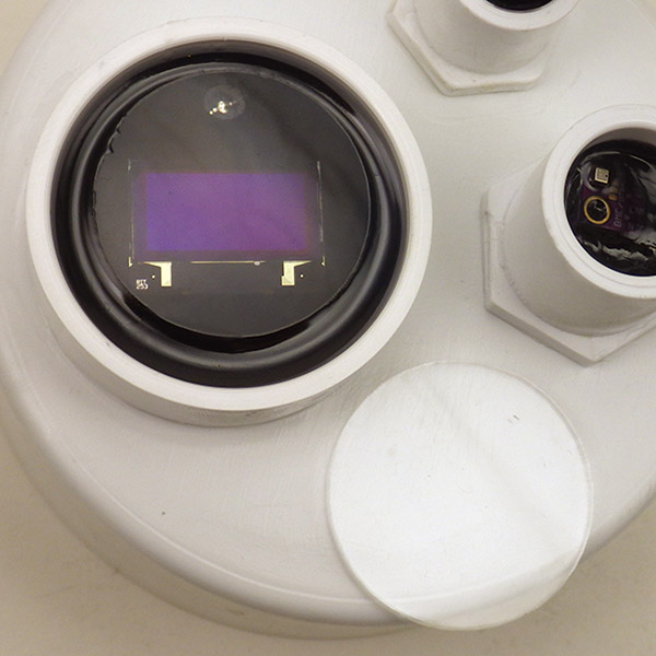
An SSD1306 OLED screen mounted on a climate station build.
This is the third installment in a series on adding output screens to Cave Pearl Data loggers. It builds on the Nokia 5110 LCD tutorial and the post describing how I store fonts in the Arduino’s internal EEprom to save program memory – so you might want to have a look at those two posts before diving in here.
While the Nokia 5110’s are a cheap, low-power option with great visibility in full sun, they reacted badly to pressure directly on the LCD surface. Since this project deploys loggers in an underwater environment I went looking for something more robust and the SSD1306 OLED’s caught my attention. (@ ~$3.50 on eBay) These little screens are showing up in hacked toys, compasses, GPS, analog meters, ECG’s, and theres even a tiny oscilloscope project at Hackaday. But those applications typically use the u8g2 library which is fantastic for graphic output, but also quite memory intensive; what I need is a bare bones solution that uses the fewest system resources on a unit that’s already near memory limits. Though these 0.96 inch displays are quite small, 128×64 pixels lets you render several lines of readable text.
While the I2C variants of this screen are easy to use, the SPI version lets me re-purpose unused analog lines to drive this display without interfering with the sensor or SD card bus because it can be driven via shift-out on any pins that are available. Powering the screen from A0 brings the screen down to zero current while the logger is sleeping, and also lets me get rid of the Reset & Cable Select lines. The only thing to watch out for is that you bring all the control lines low when you cut power so that reverse bias doesn’t end up “back powering” the screen controller.
Connecting the OLED: {Click any image to see larger versions.}
The data sheet for the SSD1306 controller specifies that the reset input needs to be LOW, during initialization, after which the pin should be HIGH for normal operation. To achieve this low -> high transition, I tie the Reset line to the middle of an RC bridge made from a 104 (0.1uF) capacitor and a 10k resistor. When you add the 25k inside the 328p used to pull A0 high, you get a 63.2% time constant of about 3.5ms.
 |
 |
 |
Begin by tinning the pins, and bending them 90 degrees for alignment with the RC bridge which also connects to the CS pin. Once that delayed rise circuit is soldered in place, also jumper the incoming GND line over to Cable Select. You would not do this if the display was on the normal hardware SPI bus, because it would exclude other devices on the SPI bus. But since we are using a separate set of wires for the display we can get away with this trick.
 |
 |
 |

The connections for the SSD1306 OLED display are the same as the ones for the Nokia 5110: (D0=clock, DC=command, D1=data in) Note that I’m not using the 3.3v rail from the pro-mini, and YOU MUST BE USING A 3.3V ARDUINO FOR THIS WIRING TO WORK UNLESS YOUR OLED BOARD IS 5V TOLLERANT. Some of the breakouts from eBay are OK at 5v, and some are not – check THIS before you buy if you are using a 5V Arduino. (Note that most breakouts sold by Adafruit include regs & level shifters to handle both voltages.)
When all the incoming lines have been added to the board, thread them through the housing and verify that the screen is still working. The analog A0-A5 lines on an Arduino can be re-purposed as digital I/O so I usually break them out with a 6-pin Deans Micro Plug (incl. GND & Vcc) In this case the screens Vcc line is being re-routed to pin-powering from A0 so the pro-mini’s rail voltage is not used. Cut away or heat-shrink over the unused Vcc pass-through on the screen side of the connector (which is still visible & exposed in the photo on the right) as you don’t want it accidentally contacting something later on inside the housing.
After the operation test, cork the pass-through hole with a bead of plumbers epoxy putty about the size of your fingertip. Wrap that putty so that it is on both sides of the wires before smoothing it down on the housing. (The sensor cap shown below has four housing penetrations sealed by this method) On the top of the sensor cap, wrap a grape-sized lump of well worked putty around the wires on the back of the screen. Then carefully press the screen down into the PVC well so that the putty compresses into a support pillar that holds the screen as near level as possible. The putty hardens in about 10 minutes and then you can pour the first layer of potting epoxy. Here I’ve used Loctite HYSOL E-60NC, with a 50ml applicator & MA6.3-21s mixing nozzles. The air space for the reflective back light forced me to use clear epoxy with the 5110 LCD screens, but since these OLED’s emit their own light, you can bring that black epoxy right to the edge of the display – covering the board & any ugly soldering… 🙂 Check the epoxy over the next couple of hours and pop any bubbles that rise to the surface with a pin. (unless you have a vacuum chamber)
 Always TEST before potting! |
 |
 |
Let that initial layer of epoxy cure for 24 hours, then drill a 7/32″ hole at a safe distance away from the screens edge. Mount an RGB indicator led inside the housing and seal it in place with plumbers putty. At this point you can simply add a second layer of clear epoxy to protect the screen, but in our experiments with the Nokia LCDs, seawater caused a serious fogging problem. So I recommend a top surface of more chemically resistant material for that kind of application. Here I’ve used a 1/4″ thick plexiglass disk (~$0.35 each on eBay).
First apply a thin layer of clear epoxy over the screens surface so that it self-levels to thickness of about 1-2mm. Then hold the edge of the acrylic disk and carefully tilt it over the epoxy film with an even contact edge that moves across the disk slowly enough to let the air escape. Don’t make that first layer of clear epoxy too thick or it will over-top the edge when the plexi settles into place and this will form blobs on the surface. Once the acrylic is in place, you can slowly add drops of epoxy on the side to bring the level up to match the edge. Give the clear epoxy another 24 hours to cure.
 |
 |
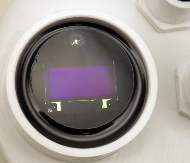 |

The display draws more current as you increase the number of pixels turned on. As a point of reference: the screen output shown above (generated from the code on Github ) draws 3.4 mA. And I haven’t seen any nasty current surges that might exceed the pin limit when the display is first powered up.
The shore hardness of the plexiglass is not much higher than cured epoxy, but the optical clarity is considerably better. The photos in this post don’t capture it well, but this mounting method really shows off the razor-sharp output you get from an OLED, and it’s readable from just about any angle. For surface loggers a 1/8″ disk should provide sufficient protection, but for the underwater units I will use 1/4″ thickness to resist the compression at depth. I won’t be able to test those underwater versions in the real world for a few months, but if the acrylic fails I will change to a stiffer glass overlay.
A few might wonder why I added an indicator LED when the logger now has full display capability. There are plenty of situations where brief LED pips communicate the progression of duty cycle events that are too fast and too numerous for screen output. I also use the LED as a noise generator when I want to squeeze higher resolution from the ADC through oversampling. These days I add an NTC thermistor to every build to capture ambient temperature.
The Code Example on Github uses a cascading method to break text strings up for single character rendering with : oledWriteString–>oledWriteCharacter–>oledWriteData and I’ve co-opted that with a new split-character method to print larger numbers to the screen in a two-pass method. The shift-out code for those functions is basically the same as that used for the Nokia 5110. I went over all that in some detail in the earlier posts so I wont re-fry those beans here. The key thing to keep in mind is that this new screen driving script uses EEPROM.read which assumes you’ve already loaded the font definition(s) into your Arduinos internal eeprom with this helper utility. That utility loads a ‘reduced’ font set to leave 500 bytes of space for file header data in the EEprom as well. (so the 5×7 font is caps only, and large characters are #’s only). If you don’t need that level of memory optimization in your build, you can switch back to simply storing the screen fonts in program memory; just transfer the PROGMEM based string->character->data functions (and the font arrays) over from in the NOKIA 5110 code example.
The housekeeping functions that take care of initializing the screen, clearing the memory, and setting the XY position are more complex for the OLED than those for the PCD8544 Nokia because the SSD1306 controller has more operating parameters. But the overall approach transferred easily between the two controllers and I suspect this method could be re-used with most of the larger SPI OLED screens on the market (like the SH1106) provided they stay below the pin current limit on A0.
Time to go shopping! 🙂
Addendum 2018-10-19:
A helpful commenter has informed me that it’s possible to try a similar approach with I2C screens because you can bit-bang I2C devices over any two spare wires. Now that we’ve pulled off this isolation trick with SPI, I’ll look into bang’n as a way to shut down high current I2C sensors when they are not in use. I’d want those off the regular I2C bus because it necessarily has a few “always on” devices that might not respond well to a lump of dead wood hanging off the same wires.
Addendum 2019-04-23:
A year long experiment in OLED burn-in. Significant dimming of the most used pixels after 4 weeks, but the screens were still operational after one year.
Addendum 2020-11-15:
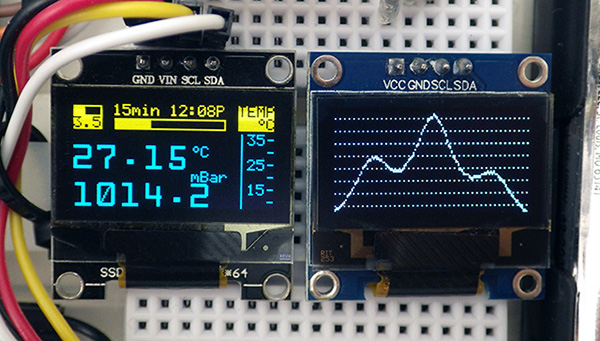
Two I2C 0.96″ OLED displays make a highly useful addition to the basic three module logger
I finally got around to updating this eeprom/fonts method for use with I2C screens
Addendum 2021-03-01:

Setting a 15-cent T233 capacitive touch switch jumpers for Momentary LOW, and removing the indicator LED for low power operation.
The one drawback of adding a OLED screens to a logger is that they use a lot of power compared to the other parts of your logger. A capacitive touch switch can be completely encased in epoxy and still function – giving you a way to trigger the display only when someone is around to see it:

