Monthly Archives: June 2014

A substantial overhaul of the Cave Pearl codebase

Driving all the new sensors that have been added over the last few weeks produced a real “herd of cats” in the codebase.  So I spent some time doing a major update of the Cave Pearl software, which is now posted at the project github. There are too many changes to list here, but a few highlights are that I2C register functions have been extracted to common subroutines and I have wrapped large sections with #ifdef/#endif statements, to make the sketch to adapt automatically to whatever combination of different sensors is attached for a given deployment  (drawing on the techniques used for the multiwii project) . I also have an scheme to replace power wasting delays (while waiting for high bit depth sensor conversions) with variable watchdog timer sleeps.

And just as a teaser, there have also been some dramatic new developments on the hardware side of things. Some of you will see that telegraphed here, but I am not tipping my hat on that till the bench-top tests give me more preliminary numbers. It will be interesting to see if anyone can spot what my next post will be about from the code alone… 🙂

Project Update: June 19, 2014

NewCropofDataLoggers

All data logging functions are now localized to these interchangeable platforms. Sensors connect via I2C

As I ramp up production for the next round of deployments, I am happy to report that the new crop of logging platforms have all passed bench testing (set RTC, r/w EEprom, r/w SD card, I2C bus coms, etc).  As I have mentioned before, lifting the tiny light sensor board lines is a bit hairy, so I was expecting at least one of these to crap out due to bridging, etc on those tiny traces.

To give them a more realistic workout, I will rotate through these units as I integrate the new sensors into the main codebuild over the next week or so. Hopefully after that I will have enough time for some proper burn tests before we go into the field again.

The 171 holders have so much tension, it usually scratches the battery just putting them in!

The 171 holders have so much tension, it can be a little hard on the fingers putting the batteries in!

There have also been a few tweaks to the power supply modules: I am now using either brass, or nylon bolts wherever possible, and the plastic battery holders have been replaced with aluminum ones from Keystone Electronics.  These holders are easily the strongest ones I have ever seen, should be rugged enough to withstand some serious knocking about.  I still have not really tackled the hard & soft iron calibration issue yet, but hopefully the removal of the stainless parts used in the previous builds will assist compass calibration when I get there.  Still running everything through Shottky diodes, but I have switched over to “Deans” style power connectors after searching the quad-copter forums for something more robust.

<— Click here to continue reading—>

Using a TMP102 temp. sensor in one-shot mode with an Arduino

Note: SDA and SCL pullup resistors have been removed.

SDA & SCL pull-up resistors have been removed.

Despite the ease with which I got the DS18B20 one wire temperature sensor running, I would prefer to use all I2C sensors for a modular system that lets me swap the data logging platform and the sensor housings in the field.  The Texas Instruments TMP102 is very low power 12 bit sensor capable of reading temperatures to a resolution of 0.0625 °C and Sparkfun sells them on a breakout board for only six bucks.

There are plenty of basic starter scripts out there that just read the temperature register, and leave the units running at the default settings. However for my long term deployments I really wanted to make use of the “one-shot” mode that this sensor supports, where the unit auto-sleeps by default until you ask it to make another reading. While this doesn’t save that much power (it brings the sensors quiescent current from 10μA down to 1μA) I figured it could also reduce the noise on the I2C lines, and the BMA180 accelerometer that shares those lines is sensitive to absolutely everything.

For those who just want a library for this sensor, there is one here and here , but I wanted a more transparent approach, because sooner or later, I will need to integrate all my individual sensor scripts into the next Cave Pearl codebuild.  If I hide my functions in a library, it will be that much harder to see where duplication might be eliminated.

Because this sensor stores data in 16 bit registers (outlined here, but their code is somewhat confusing) , you have to do some juggling to reconstitute the data after reading out two register bytes.  This gets a little complicated if you reach temperatures below zero because the negative numbers are represented in binary twos complement format. Fortunately that is not an issue in caves, and the twos complement stuff does not need to be done on positive numbers. You also don’t need to get into the 13bit “extended” mode of this sensor unless you are measuring temperatures beyond the normal  –25°C to +85°C range.

You can download my TMP102 script HERE, This code produces the following output:

Initializing TMP102 Temperature sensor…
Integer data before conversion: 458
Temperature in deg C = 28.6250
Success:TMP102 has been initialized
Integer data before conversion: 457
Temperature in deg C = 28.5625
Integer data before conversion: 458
Temperature in deg C = 28.6250
Integer data before conversion: 480
Temperature in deg C = 30.0000
Integer data before conversion: 485
Temperature in deg C = 30.3125
Integer data before conversion: 489
Temperature in deg C = 30.5625
Integer data before conversion: 492
Temperature in deg C = 30.7500
….

(Note: I had my finger on the sensor here, to show the readings changing…)

The readings stabilize pretty quickly on the desktop, which is always good to see with a new sensor. Now that I have it running, I will build a special test unit with the TMP102, the DS18B20  (identical to TMP102 specs: 0.0625 °C/lsb & ± 0.5°C), and one of the MS5803 pressure sensors installed (16 bit resolution of 0.01°C but poor accuracy ± 2.5°C). That should let me assess issues like offsets, drift and noise as I select the best temperature sensor to adopt.  I will have the 102 potted in JB weld on the outside of the housings, so I suspect there will be some thermal lag to deal with as well. (I wonder if I could use some kind of heat pipe there?)

Addendum 2014-06-17:  

If I have issues with the TMP102, I may try to get a hold of a TMP112 which is code compatible, and has a slope specification that can be calibrated for better accuracy.

Addendum 2014-12-08:

I will post more detail on this later, but since I just ran across this problem, and I thought I should post to let other people know about it: For a long time I though my TMP102’s had a weird spiky noise problem which I tried to hammer out with sample averaging, but it was not the sensor, it was the floating point calculations on the Arduino. The two graphs on the right were derived from the raw sensor data with exactly the same equation:

Dont do float Calculations on ARDUINO

It’s possible that I caused this problem by forgetting to use proper casting in the calculations.

ie:  TEMP_degC =TEMP_Raw*0.0625   vs  TEMP_degC =(float)TEMP_Raw*0.0625 

but just in case, I am going to avoid float calculations on the Arduino.  You can always save your “raw” sensor data for processing later. 


Github launch for the Cave Pearl Project

A benchmark of sorts for the project today, as I finally got around to setting up a Github for the Cave Pearl Project. As I learn more about coding, and add more sensors to the platform, the scripts for each build have grown well beyond the size that I can squeeze into blog posts on this free WordPress account.  Now the code that I share will be somewhat more readable for other DIY’ers, as Github has a nice formatting scheme. I can also fork (and hopefully contribute back to) other code that is hosted there, as I am always on the lookout for more useful scripts.

Because site stats show me that people Googling individual sensors represent the largest volume of traffic to this blog, I have already posted all of the small “single” sensor scripts. I will work my way through the older datalogger code builds, transferring them to the Github folder in a more or less chronological order. It will take me some time to get that sorted as I will also try to cleanup the formatting a bit in the process.


Using a BMA180 with an Arduino as a tilt sensor

I know you are supposed to decouple Vcc and Vdd, but I have not figured out how to do that yet.

Plenty of these old geeetech breakouts selling on eBay. I know I am supposed to decouple VDD and VIO, but I have not figured out how to do that yet.

Up to this point I have been measuring displacement with the Bosch BMA250 on the Tiny-Circuits accelerometer board. But that sensor has a minimum range of 2g, using less than half of its 10 bit ADC in my tilt sensing application. Given that just about every electronic widget these days seems to rely on haptic feedback, I thought there would be a selection of other sensors out there to choose from in the 1 g range, so I was quite surprised to find out that there are only a couple of low g sensors on the market, and only the Bosch BMA180 uses an I2C interface.  I was already using the 250, and that was pretty easy to get rolling, so I thought that it was going to be a piece of cake to switch over….

But the BMA180 is the gnarliest sensor I have worked on to date, with a spaghetti monster of co-dependent register settings, and an obtuse snarbuckle of a data sheet.  But a 14bit ADC at 1g would almost triple the sensitivity of the Cave Pearls (In theory, registering a 0.25º tilt change), and for that I was willing to spend a week learning a bit about shift notation and masking to use this incredibly twitchy bit of kit.  And reading data out of the registers is not even the biggest challenge: trade-offs between sensitivity and spiky random noise rapidly gets you into a tangle of offsets, sampling frequencies and filtering modes that don’t get explained at all well in the documentation.

I started out with general accelerometer references by Texas Instruments, and Freescale, which tend to focus on the calculations required to turn generic accelerometer readings into roll, pitch and yaw. From there I found a few BMA180 link pages, but most of the sites were for dedicated quadcopter IMU’s like the multiwii, which generally combine data from an accelerometer with that from a gyroscope, using complementary filters or more complicated Kalaman filter calculations. Most of these approaches are aimed at real time smoothing of continuous data streams, while I am interested in infrequent, high accuracy readings.  There were a few seismometer projects, which showed me how to set the range, frequency & bandwidth filters, but they usually focus on getting interrupt alarm modes working, which is not useful for my application. Some mentioned calibration in passing, but there still was not much signal to noise optimization being done, and after several days I still could not find a single example of someone putting the sensor to sleep between readings to save power.

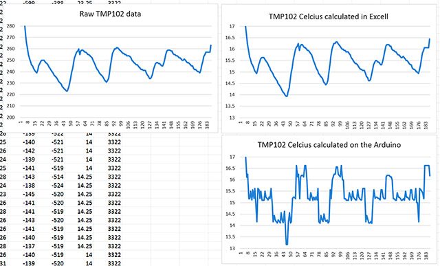
Once you start sending the readings to the serial monitor, you see how jumpy this sensor is just sitting on the desk, in low noise mode, with the lowest availiable bandwidth filter (10Hz).  I tried a moving average with the arduino library, and then using a basic smoothing routine, but the readings were still pretty unstable. I finally managed to tame the gremlins with the digital smoothing method from Paul Badger, which throws away the high and low values from a set of readings, before averaging the rest of the data. The trade off here is that while this sensor only draws 1025µA in low noise mode, I have the whole system running for 1 second to capture enough readings for this process.

Note: the sensor was not level here, just hanging on some wires.

Note: the sensor was not level here, just hanging on some wires, so the x & y axes are not zero.

Given how tough it was to get this far, and how few people are using this accelerometer as a stand alone device, I though I would post the rough BMA180 accelerometer script which now produces reasonably stable 14 bit readings. The code has a nice function for dealing with individual register bits with a mask, which I am sure will come in handy for other sensors. I still don’t grok hex numbers, so I have written the masks as long form binary so I can see exactly which bits are being modified.

As I am using the BMA180’s default low-noise mode, I am simply relying on the factory calibration in the sensors ADC. But occasionally one of the readings will spike over 16384, so I know I still need to implement further offset calibration. I have already tried a few simple “high/low” methods, but most of them have actually made the x & y offsets worse (perhaps I need to use a jig for calibration?) and it will be a while before I can tackle least squares or gauss newton . To be honest, I am not even sure if its worth trying to attempt the 3D ellipsoid corrections on the Arduino’s cpu. (and I don’t know if my “organic” processor is up to the task either 🙂 )

Addendum 2014-11-04

I finally figured out how to get the BMA180 sensor sleeping to save power between readings:

// first check if the sensor is in sleep mode by looking at the content of bit1 in CTRL_reg0
// if so wake up the sensor by setting the sleep bit (bit1 of reg0) to “0”
// you do not need to set the ee_w bit before doing this!
// but the dis_wake_up bit must be “1” to disable the auto-sleeping function first
// (I do this in the initialization)

bytebuffer1 = i2c_readRegByte(BMA180_ADDRESS, BMA180_CMD_CTRL_REG0);
bytebuffer2=bytebuffer1;
bytebuffer1 &= B00000010; //knock out the other bits
if(bytebuffer1){ // if “true” then the bit was “1”
bytebuffer2 &=~ (1<<1);     // forces 1st bit of bytebuffer2 to be 0. all other bits left alone
bytebuffer1 = i2c_writeRegByte(BMA180_ADDRESS, BMA180_CMD_CTRL_REG0, bytebuffer2);
delay(10);// now give the sensor some time to wake up
}

… now take your readings….

and then to put it to sleep again:

// put the BMA180 sensor to sleep again by setting the sleep = bit 1 of reg0, to “1”
bytebuffer1 = i2c_readRegByte(BMA180_ADDRESS, BMA180_CMD_CTRL_REG0);
bytebuffer1 |= (1<<1);      // forces first bit of bytebuffer1 to be 1. all other bits left alone.
bytebuffer2 = i2c_writeRegByte(BMA180_ADDRESS, BMA180_CMD_CTRL_REG0, bytebuffer1);

BMA180connections

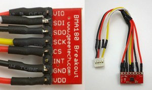
Connecting to Vcc and GND further along the cable is easier than putting little jumpers on the surface of the board.

Because the sensor now sleeps below 1uA, I can let it run in its power hungry (~1mA) low noise mode when I need to take a reading, without having to worry about other power saving from things like the oddly named “wakeup” modes. The bitmath is from CosineKitty’s tutorial at the playground which showed me how to toggle just that one single bit in the register.


Bench-top Power Test Results : May – June 2014

The part swaps in March left me with a complete “spare” pendulum unit to bring back home. This has proved quite handy to explain the design to people, but I was keen to do a complete power test with the build, as I had set one of the pendulums in the cave to a short 5 minute sample interval, not knowing if it would go the distance.

Until I get my hands on an EEVblog uCurrent (or perhaps a Fried Circuits USB tester..?), there is only one way for me to determine power usage of the whole system, and that’s simply to plug one in and let it run. So on April 23rd,  I set the spare unit up on a bookshelf with 3 AA alkaline batteries, and a sample interval of 1 minute (to give the batteries a recovery period). Since then this test has been interrupted a few times due to random bumps during show and tell sessions. The gap around 20 000 samples was interesting in that the RTC alarm signal kept working, but the unit stopped recording the date/time data when an I2C wire was broken during handling. The Tinycircuits compass board level shifters kept the unit running, despite the loss of the other I2C lines, until I noticed the break and repaired it.

20140609_DryPowerConsumptionTest_graph

Vertical grey lines ~ 2000 records:  approximating one month of samples at 15 minute interval.

These results are as good as I could have hoped for: >61 000 records recorded on the SD card, with the power supply falling from 4380mV down to 3750mV (read with the internal Vcc reading trick, after the shottky diodes on the power module). That’s around 22 months of operation if we were capturing data every 15 minutes, and the units currently installed in the caves have twice as many batteries in them. Even better, this test is still comfortably on the alkaline battery power plateau –  nowhere near the 2800 mV cutoff I set in the code to protect against unsafe SD card writing. I intend to let this test run to completion to see how gracefully the unregulated unit handles the eventual loss of power.  Since I have a 3v button cell backing up the DS3231 RTC, my guess is that once the main power supply falls below that point, the RTC will sleep, and stop sending the wakeup alarm to the logging platform. This would be a fairly graceful fail if it happens that way, but the data could get choppy for a while as Vcc wobbles by 50-80 mV from one reading to the next in the current record. I will just have to see how it goes as I still have quite a few component changes to work through before I start counting chickens. My plan is for the next round of deployments to compare data from several different sensors measuring the same parameter in the same unit.  So there will be a one-of build with three temperature sensors, or three accelerometers, etc., making good use of the excess power available at this stage.

Addendum 2014-06-12

I just reviewed the DS3231 data sheet again, and the DS3231 is designed to keep running from Vcc well after the main supply falls below the voltage of the rtc backup battery.  The actual “Power-Fail” voltage”, where a low VCC stops the SQW alarm,  doesn’t kick in until somewhere between 2.45v min – 2.7v max. All below the 2.8 volts minimum for safe SD card writing. So it looks like the system clock wont give me a graceful power out behavior unless I somehow lower the RTC’s input voltage below the rest of the system ( by .2 to .3v …perhaps with a Shottky diode?). Interestingly, you can go the other way if you need to: Bit 6 (BBSQW) of the DS3231’s control register 0Eh, can be set to 1 to force the wakeup alarms to continue when running the RTC from the back up battery alone. Not useful here but perhaps on another project. 

Addendum 2014-06-12

 The power drain test with this unit was finally completed on Aug 06, 2014, recording 390000 records with 3 alkaline AA batteries.

Addendum 2014-09-21

The real world results were dramatically different from this bench testing, due to excessive sleep current being drawn by counterfeit SD cards in the deployed units.