Project Update: Gearing up for field work 2014-11-26

Using Loctite E00-CL this time round.

Using Loctite E00CL this time round. The epoxy is weaker overall, but claims higher shear strength on PVC than E30-CL. The faster epoxy gets hotter, and contracts more, so there may be some risk of lifting the components. And the numbers in the individual data sheets do not exactly match those in Loctite’s own Plastics Bonding Guide, so who knows?

Another field trip is rapidly approaching, and I am scrambling to finish the bench tests before we have to stuff everything into a suitcase. The last three months have seen the project migrate away from the unregulated TinyDuinos as the heart of the data logging platform, to RocketScream based builds. Most of my sensors require a regulated 3.3 volt supply, and with only one MCP1700 voltage regulator in the mix, the Ultras have been delivering better sleep currents overall.  The MCP also gives me the ability to use lithium batteries in a pinch (who’s over-voltage would fry the unprotected processor on a TinyD board) , and it delivers up to 250mA if I end up with really power hungry sensors later on. Now that I have the same core logging platform in all the different Cave Pearl models, it is easier to shave down my code, as the compiles keep bumping up against the 32k limit for multi-sensor configurations like the pressure/temp/RH unit

But I have not forgotten how the TinyDuinos catapulted this project into viability back in 2013, and I am waiting to see if they release a generic I2C driver shield. Despite my rough handling of those early Tiny-based builds, most of them are still chugging along after months under water, a tribute to the quality of their build. I enjoy soldering my little bots together, but anything you have to do a hundred times begins to loose it’s luster.

Cave Pearl Flow Sensor

With new 32k EEproms in the mix, space on that logger platform is getting pretty tight and I have to trim the groove hub pcb to make more room.

Bench testing over the last few months has seen more sensor failures than I can throw a stick at, and I am sure that there are more to come if I keep using cheap eBay vendors.  The best overall diagnostic to identify good breakout boards continues to be shutdown mode current. If it’s on spec, and the board delivers a stable reading after wake-up, your golden.  Along the way, there have been so many little code tweaks I could not even begin to list them all. Some, like having the sensor reading LED pip change color to also indicate battery status, were effortless. But others, like determining the optimum number of times to use precious power up cycles to check that battery status, still have me scratching my head. We have more than 12 new loggers to deploy this time round, and I will be embedding plenty of little mini-experiments in the code to give me some empirical data for those questions.

You need at least a week of dry runs, as some sensors fail after a few days of operation.

You need at least a week of dry tests, as some sensors don’t fail till they have been running for a few days.

At this point I am focusing on micro amps, not milli amps, and the best drip sensor builds are coming in with sleep currents in below 15 μA (if I get all the sensors in to their low power modes and pin-power the RTC) That’s a heck of allot better than I was expecting for a few jumpers connecting off-the-shelf breakout boards. Even with the physical build coming together well, I still have a huge sensor calibration to-do list hanging over my head. But the tickets already bought, so that will have to wait till after the next set of field deployments. I also need to develop a new bench testing method that gives me the ability to discriminate how relatively subtle code changes affect a micro-power budget. Oscilloscopes seem to capture a time window that is too brief for the complex duty cycle of a data logger, and the power use ranges from a few μA of sleep current to many tens of mA for SD card writing during each cycle.

Hmmm…

<— Click here to continue reading the story—>

Sleeping an MCP9808 on an Arduino based Pressure, Humidity & Temperature logger

As I gear up for the next round of fieldwork, I thought I would introduce the newest addition to the Cave Pearl lineup: A logger for Pressure, Relative Humidity, and Temperature

Left: MS5805-02, HTU, MCP9808  Right: MS5803-02, HTU ,TMP102

Left: MCP9808, HTDU21D, MS5805-02          [rgb LED on both]          Right: HTDU21D,  TMP102,  MS5803-02

When one of the drip sensors from the last deployment failed early, I went hunting for information to see if I could corroborate the dramatic increase in drip rate it recorded before it expired.

 The wires of the housing pass-through always push the boards into odd angles, so I level the boards with a preliminary 'underlayer" of cured epoxy while applying some top pressure with a pin to hold things in place

The pass-through wires push the breakout boards into odd angles, so I tack them down with a pea-sized bead of JB Plastic Weld while applying some top pressure to hold the board level. (takes ~15 minutes) Then I test the sensors “dry”, while they can still be removed. Potting in epoxy is the last step.

This made it clear that there really was not alot of good climate station data near our deployment site, and that even if that data was available, it still was not going to tell us much about the conditions down below. So I spent a couple of days cobbling together these mini “in-cave” sensor stations. I will try adding an anemometer to them them later, if I can find one that draws a low enough current to operate within my power budget.

These first units which will be co-deployed so that we can compare the performance of the different sensors. One uses the MS5803-02 sensor (already proven robust enough for five months at 5m in 50% marine water), and the other is using the much more affordable MS5805-02 which is only listed as ‘splash-proof”. This comparison is test was almost effortless to do, as both sensors are code compatible, with the exception of the CRC check.


CarefullyEpoxytheProtectiveCap

The cap fits because the HTU21D  from Measurement Specialties has a similar form factor  to the Sensirion SHT series humidity sensors. But you need to cut the legs off the cap to flush mount on the Sparkfun board as I have here.

For Relative humidity I am using the Sparkfun HTU21D with the Sensirion SF2 protective cap. The trick to installing these caps on the sparkfun board is to first bond the cap to the board with a tiny amount of epoxy applied all the way around the base of the protective cap with a toothpick. Once the cap is bonded to the board you can cover the rest of the topside of the breakout with epoxy, taking care not to let it run up to the protective fabric, where it could wick in and seal off the sensor. Hopefully this waterproof cap will protect the sensors well enough, but I am not expecting miracles because most RH sensors go a bit squirrly in caves, where the environment can be at 100% RH for a good deal of the time. I was very happy to discover that this sensor auto-sleeps after each reading, so it adds almost nothing to the power budget. The units are going into the field in a few days, so I will have to look at something like salt calibration of these humidity sensors later.

Good old JB plastiweld lets me tuck the Groove hub up out of the way, as all the real estate on my platform is taken up with the battery holders.

JB Plastic weld putty lets me tuck a trimmed Groove I2C hub up out of the way, so only one I2C jumper runs from the cap to the logger platform, taming the spaghetti monster.

For the hat-trick I am trying out two different I2C temperature sensors. Technically speaking, the pressure and RH sensors already collect temperature data, which they need for their internal calibration, but I just thought that it would be nice to do a little experiment comparing Sparkfuns TMP102 to Adafruits MCP9808.  While their precision is identical (0.0625 C), the 9808 claims much better accuracy.

I already had the TMP102’s working in one-shot mode, but even Adafruits generally good code support did not cover putting the MCP9808 into its low current shut-down mode, and this is critical for my application. A little browse through the datasheet, and it turned out to be pretty easy to do, and I thought I would post this for others wanting to use the MCP9808 for logging:

byte bytebuffer1 =0;
byte bytebuffer2 =0;
#define MCP9808_REG_CONFIG 0x01
//
void MCPshutdown() {
Wire.beginTransmission(MCP9808_I2CADDR);
Wire.write((uint8_t)MCP9808_REG_CONFIG);
Wire.endTransmission();
Wire.requestFrom(MCP9808_I2CADDR,2);
bytebuffer1 = Wire.read(); //upper bits first 15-8
bytebuffer2 = Wire.read(); //then bits 7-0//set “bit 8” to “1” to enter shut down mode
bytebuffer1 |= (1 << 0);
//x |= (1 << n); // forces nth bit of x to be 1. all other bits left alone
Wire.beginTransmission(MCP9808_I2CADDR);
Wire.write((uint8_t)MCP9808_REG_CONFIG); //register pointer
Wire.write(bytebuffer1); //
Wire.write(bytebuffer2); //this one is unchanged probably could skip it
Wire.endTransmission();
}
//
void MCPwakeup() {
Wire.beginTransmission(MCP9808_I2CADDR);
Wire.write((uint8_t)MCP9808_REG_CONFIG);
Wire.endTransmission();
Wire.requestFrom(MCP9808_I2CADDR,2);
bytebuffer1 = Wire.read(); //upper MSB bits 16-8
bytebuffer2 = Wire.read(); //then LSB bits 7-0//set bit 8 to 0 = Continuous conversion (power-up default)
// x &= ~(1 << n); // forces nth bit of x to be 0. all other bits left alone.
bytebuffer1 &= ~(1 << 0);
Wire.beginTransmission(MCP9808_I2CADDR);
Wire.write((uint8_t)MCP9808_REG_CONFIG); //register pointer
Wire.write(bytebuffer1);
Wire.write(bytebuffer2); //this one is unchanged probably could skip it
Wire.endTransmission();
}

Except for the bit-math, I use the same method here to wake up and shut down the sensor, but since the default values of the config register are all zeros, you could also use the much simpler:

void MCPwakeup() {
Wire.beginTransmission(MCP9808_I2CADDR);
Wire.write(MCP9808_REG_CONFIG); //register pointer
Wire.write(0b00000000);
Wire.endTransmission();
}

to reset all defaults & launch continuous measurement mode.  I think the soft reset does the same thing, but I have found that some sensors make you wait much longer after a “soft reset” before they give you good data than they do if you use a sleep/wake method. When possible I let my  sensors go through a couple of conversion cycles to flush old data out of the registers before I read them.

I have also learned some hard lessons about not trying to do calculations on a limited platform like the Arduino if I can avoid it. So all the sensor data is being saved as raw output in the log files.  I always get better results when I do the conversions later with a spreadsheet.

…And just to go completely over the top, I also record the temperature register of the DS3231 RTC. While this is certainly the least capable sensor in the mix, I am curious how it tracks against the others, in terms of accuracy.

Addendum 2015-02-27

As I put the first units into the field a couple of days after they were built, I did not have a chance to really play with them. So I recently built a couple more, using the TMP102 for temperature, MS5805-02 pressure sensors. One was built with the Sparkfun HTU21D breakout, while the other used a $5 noname HTU board from eBay.  In my tests so far, both deliver identical humidity readings, and both of these mini ultra based loggers sleep at 0.08 mA, which bodes well for these guys making it to my year of operation benchmark.

Addendum 2015-06-22

After building a few more of these I ran into a problem with epoxy wicking into the RH sensors before it cured. This is impossible to see under that SF2 protective cap so the only option is to drill out the bad sensor the next day. To prevent this from happening again, I now pot the RH sensor without the caps, and then tack the cap down with plumbers putty after the epoxy is dry:

Project Update: the Next Generation of Drip Sensors

It’s been a while since I made a post, as the basement workshop is in now in full swing assembling units for the next round of fieldwork. But I recently found out (thanks to Fernanda at Rio Secreto) that one of the drip sensors we installed in August croaked early, with a suspicious order of magnitude increase in the number of drips it recorded just before the battery took a nose dive:

Unit3_RioS_PowerCurveGraph_201400726-1010

Local climate stations don’t show that kind of increase in rainfall, and the batteries did not leak,  so my first thought is that the ADXL345 went through some kind of failure, self-triggering as it brought the whole unit down. But before that event, the battery voltage was good (I used lithium AA’s, which is why they started so high), so even with fake SD cards pulling alot of sleep current I think the other units will survive until we can retrieve them. To be honest, those first drip sensors were a dogs breakfast of different components, and most were cobbled together the week before the trip, so I am surprised that we only have one dead soldier so far. The fact that the data on the SD card survived a complete loss of power is also very good news.  I am actually looking forward to examining that unit, as it is the first hardware failure we have had in the field(I wish I could say the same thing for my code…)

Cave Pearl Drip Sensor Data Logger

With the usual quid pro quos of a highly variable duty cycle, this kind of sleep current might get me in to multi-year territory on 3 AA cells.

For the new set of builds, I have made a few changes to reduce the power consumption of the logging platform.   With a design goal of one year, continuous operation, I have decided to leave out the Pololu  switch, as it wastes too much power when you only have 3 AA’s. The Muve music SD cards from eBay have all been great low current sleepers, bringing my typical build with a Pro Mini clone board into the 0.25mA range. Powering the Vcc line on the RTC from a pin on the Arduino saves another 0.089 mA, and taking advantage of the MCP1700 on the Rocket Ultra brings my best builds down to 0.13mA  with a sleeping SD card (~ 60 µA) and an ADXL345 running (~ 50 µA) to provide interrupts.  Of course, there is always the chance that the RTC will not survive repeated switching on it’s power supply, so I will only test this technique on a couple of units in the next deployment.  If they survive without running the CR2032 coin cells dry, I will adopt this modification for the whole Cave Pearl line. It doesn’t sound like much, but that little RTC breakout will eat 600 mAh (1/4 of a AA) if you power it from Vcc for a year.

When you disconnect Vcc, the DS3231 goes into a 3uA timekeeping mode.

Here I have lifted the Vcc line from the RTC breakout board.  When this line is pulled low by the Arduino, the DS3231 goes into a 3uA timekeeping mode, saving 89uA

As a point of comparison, I tested an “unregulated” TinyDuino stack with the same code, SDcard, RTC, ADXL and battery pack, and it only went down to 0.55 mA while sleeping. Lifting the tiny light sensor board I2C lines, and having the SD card in place, means that the Tinyduino stack actually had two live voltage regulators, while my Rocket based loggers only have one. (Also, I don’t think they are pulling up the unused data lines on their SD shield, so floating pins might be increasing the SD sleep current a bit.)  And while having a regulator on every shield affects my particular application, I can see lots of good reasons for that aspect of their design. I still love the overall form factor of the TinyDuino’s, and the significant amounts time I spend soldering these loggers together has me patiently waiting for TinyCircuits to produce a generic voltage regulated, level shifted, I2C communications shield, so I could spend more of my time fixing code bugs instead of soldering (hint..hint!) It takes me about four hours to build one of these drip loggers from scratch.

I simply let the wires I am already using to tap the cascade port I2C lines poke up enough to give me solder points for the EEprom. Don't forget to remove the pullups on the EEprom board.

I simply let the wires I am already using to tap the I2C cascade port poke through as solder points for the EEprom.

The final upgrade in this iteration the addition of a 32K AT24C256 eeprom. With the testing I did back at the beginning of the project, I know there is a chance that this much I2C bus traffic (buffering up to 512 records if I fill the whole thing)  might not save much power, but it lets me standardize the data handling to one SD writing event per day no matter how many sensors are attached, or how short the sample interval is.  I will have a couple of the drip sensors buffering five days worth of data on the next deployment, to see if using this eeprom to condense five smaller SD card events into one big one  (which takes about 2 seconds to complete)  reduces the long term power consumption of the loggers. And finally, if the unit has a catastrophic power failure that completely toasts the SD card, there is a good chance that I will be able to retrieve the records buried in the eeprom for forensic analysis.

Having a second eeprom in the system also lets me “reserve” the little 4K AT24C32 on the RTC breakout for calibration data. While this is not that important for the drip sensors, it will come in quite handy as my flow sensors mature, and I start to tackle things like hard & soft iron correction on the magnetometer.  The drip loggers are so quick to make & deploy, they have become my low-risk test platform for new ideas.

Drip sensor test rig

Life was easier when I only had one calibration stand. Testing multiple units at the same time turns you into the proverbial man with two watches…

And speaking of test platforms, I now have two testing riggs set up for the drip loggers as they come off the bench, and they have taught me a very valuable lesson: Whenever you invent a new device, you also have to develop a new calibration protocol; which can turn out to be more challenging than building the actual device. Initially, I thought that all I would need for the job was a graduated cylinder and a funnel with some kind of flow limiter.  But my initial test results were all over the place, with the counts varying by 30% or more from one run to the next. At first I blamed the accelerometer thinking “It must be registering multiple counts, or it is just not firing the interrupt when it should”. I tried different sensitivity settings, varied timing delays, everything I could think of. But nothing seemed to improve the consistency between runs, and after many tests with crummy numbers, I was beginning to think I must be missing something fundamental.  I was so frustrated by this I decided to just sit there, staring at the little LED and counting the drops myself for as long as it took to figure this out… And I am really glad I did, because an hour into this caffeine powered exercise in utter boredom I had sore eyes, but I knew beyond shadow of a doubt that those sensors were working fine. Every drop was being counted. Every last one. So what was throwing the numbers?

Surface splatter from a drip impact. The green light is the LED indicating the count.

I made several attempts to capture photos the surface splash after a drip hits, as I thought this was throwing the counts off. Here you see the green LED light being triggered with five or six splash-drips flying away from the point of impact.

Google didn’t bail me out on this one, and all Wikipedia gave me was an article on how drip volume depended on the relationship between surface tension and tip radii.  But both funnels had the same 8mm pex tubing, hand polished smooth, as the drip source point, and they were still giving dramatically different results. It was time to call in the big guns, so I asked Trish to let me root around the Web of Science the next time I was at her office. That lead me to this paper:

Controls on water drop volume at speleothem drip sites:  An experimental study
by Christopher Collister and David Mattey, published in the Journal of Hydrology.

I used heat-shrink to get nice sharp 5mm diameter tube tip.

I  also used heat-shrink to make a much smaller  5mm  drip tube, further reducing the drip size.

In that paper there is a graph (pg 264) that illustrates: “At fast drip rates with drip intervals less than about 10s, drop volumes are seen to increase with a greater degree of scatter in the mass of individual drops.”  Their plot had almost 50% drip volume variability when the drip interval fell to 1 second. I had been testing my units at 3-6 drips per second or more, because I was worried about clipping the high end with all the delays I put in the code to prevent double counts from splash back. I also thought that with more runs, and larger the volumes of water (which increased pressure above the drip), I would be reducing the errors.  I went back with a magnifying glass, and sure enough, I could see the water surface tension shaking like a struck drum after each drip detached, and this wobbling increased dramatically with the rate of flow. Fortunately the paper also provided a solution to my problem:  “The results confirm that drop volumes are essentially constant at drip intervals greater 10 seconds.”  So I completely changed tactics, going for lower volumes and slower drip rates. On the very next try, I was getting data like this:

Unit 10: 500 mL
Drip Count: Time to complete: Drips/Min (max)
6289 135 min 62 dpm
6281 138 min 64 dpm
6314 141 min 63 dpm
Unit 10: 1000 mL
13097 246 min 70 dpm

At about one drip per second, I am still running these a bit fast. It will be a while before I get “ideal” interval tests done as they will take at least ten times longer to perform.  You can see how the larger 1000 mL volume pushed the flow rate up a bit, increasing the 500ml equivalent count up to 6548.  But even at 1 second intervals, I am pretty sure my handling of the graduated cylinder is on par with drip variation as a source of error. And the two different test rigs are within a couple of percent of each other now as well.

Whew!

Addendum 2014-12-02

Since the GSA, I have had people asking when I would have the drip counters for sale, and this post will likely trigger a few more enquiries. Right now every unit I can put together is earmarked for my wife’s research, or projects with other researchers who are helping me improve the overall design. So before that trickle becomes a flood, I should point out that plain old tipping bucket sensors are dirt cheap, and they are pretty easy to hook up to any arduino logger you can find (some people even hook them directly to bicycle speed loggers or calculators. And if you want it wireless, you can use a doorbell). There are some very interesting alternatives in the weather station station market (like the Hydreon RG-11, though at 15-50mA it’s a non starter for battery powered loggers) There are also plenty of lab-based drip counters out there that use approaches such as IR beam deflection or even photo interrupters / optoisolators.  A fair number of people are working on acoustic rain sensors. And finally there is already a drip counter on the market specifically for cave research: The Driptych Stalagmate. The Driptych uses a piezo sensor to detect the impact of the drips. While I have never seen one in person, I can guess that if they are able to use the voltage spike from the piezo to trigger the interrupt line directly, their loggers might be able to operate with an extremely low sustained power draw. In comparison, my accelerometer based approach will probably always pull at least 0.06 mA to keep the sensor ticking over, so I have a ways to go before I reach the four years of operating life they offer, not to mention all the other little bugs I still have to sort out. I am just having a heck of allot of fun doing it.

Addendum 2015-05-29

I recently tried replacing the accelerometers with some very sensitive 18020P shake switches. This removed the constant power drain of the accelerometer, but they also made it fiendishly difficult to adjust the sensitivity. Those simple vibration detectors are not standardized very well, so you have to rotate the switch in 3d space to find the best response angle for each individual one. (unlike the accelerometers, where its just a simple register setting) Tilt it a little too far and the switch will just self trigger, not far enough and you have to hit the thing very hard (relative to drip energy) to trigger the interrupt.  And when you have it in the right physical orientation for “light” drip impacts to register, the spring continues vibrating for quite a long time after receiving a “hard” drip impact.  Those “echo” triggers stretch well past 150-200ms, causing the problem that when the water is really flowing, and the drop volumes increase causing harder hits, the settling time gets longer and longer, so the sensor itself imposes a fairly low maximum detectable drip rate after which the spring mechanism is just triggering all the time.

<— Click here to continue reading the story—>

Cave Pearls at the 2014 Geological Society of America Conference

We just returned from presenting the Cave Pearls at the GSA in Vancouver!

Having a lineup before you even finish setting up the poster in the morning is always a good sign...

Having a que form before you finish setting up the poster in the morning is always a good sign…

Since we left most of the operating data loggers we had in Mexico on our last trip, I had to scramble to build a few more before the conference. I also spent an inordinate amount of time making the poster look pretty, as this was our first “formal” pitch of the Cave Pearl system to the academic world. (and that is my day job right?)  While all of this was old hat for a career academic like my wife, I admit I was a bit nervous, and somewhat uncertain if there would be any interest at all.  A few researchers had already expressed to me the opinion that any time they had to spend building sensors or equipment represented an unacceptable opportunity cost. (ie: that time could be better spent on grant writing to buy commercial equipment)  and some of the more technically inclined people simply dismissed AVR based Arduinos as a second-best option, suitable only for hobbyists.

But overall, the presentation was very well received, and we had a constant stream of interested people that kept both of us busy talking all day long.

Trish describing the flow sensor deployments

Trish describing the flow sensor deployment dives.

I created a display stand for the flow sensors, to explain the principle of the hydro-metric pendulum, and we had a “live” drip sensor operating under a suspended funnel of water. It’s blinking led drew some people in and I had several open units to put into their hands so that they could see how simple the physical build was.  I suspect that a few research groups will now be adopting my data logger platform, and I gave away a couple of drip sensor units to help some of them get started.  It made my maker-heart happy to find out that several other groups were already investigating various Arduino mcu boards, and they were impressed to see my loggers sleeping below 0.25 mA with the sensors running to provide interrupts. (there was no Pololu power switch on that one)   Many of them are at about the same stage that I was at a year ago,  so hopefully the code I have developed will help to advance their projects more rapidly.

So now we have several new groups to collaborate with, which will be handy when it comes time to co-deploy my DIY sensors with some commercial equipment for calibration. Of course, now I need to get a technical paper out the door…so those guys have something other than this humble blog to cite.   🙂

<— Click here to continue reading the story—>

The DIY Arduino datalogger with low power shut down capability (2014)

Addendum 2017-02-20:

This original $10 DIY Arduino logger page was posted in 2014, and there have been several significant updates to the way I assemble the basic three component design since the early version described in the post below.  If you are building your first data logger you might want to start with the new one-hour build:  1-hour Pro Mini Classroom Datalogger  Most importantly, as the build achieved lower and lower sleep currents, I stopped using the Pololu power switch described below, as it ended up using more power than the sleeping loggers themselves.

Also note: The Pololu power switch described in this post has been superseded by the vastly superior Adafruit TPL5110 Low Power Timer.  Cfastie has been putting this board through it’s paces over at PublicLab.org.


Original post from  2014-10-07:

Here is the latest version of my basic DIY datalogger, which adds a new component to the design:

A3 component DIY data logger

Note: There is a set of detailed build instructions for a pro-mini based data logger from this plan at:  Part 1 Part 2 Part 3 

NoteAdapter pin numbering follows this document: 1 = Chip Select, 2=Data in = MOSI, 3 = GND, 4 = VDD (supply voltage, not > 3.3v!), 5 =SCLK , 6 =GND , 7 =Data out =MISO
Several sources recommend pullups on CS, MOSI, MISO and SCK, though the loggers will usually work ok without them. But testing has shown that some SD cards take a very long time to go to sleep unless CS, MOSI & MISO are also pulled up

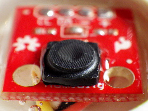
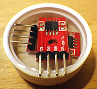
The addition of the power switch solves the last nagging problem I had with the original 3-component design: unpredictable system behavior when the power supply goes low. I knew from my bench tests that some boards (like the Rocket Ultra pictured here) gracefully go into a kind of holding state till they completely brown out, while others go into a kind of power cycling loop, alternating off & on, when the battery voltage gets too low for the regulators. Now, you can just read the divider and drive the control pin high to shut down the entire system. Of course, everything is a trade-off, and this soft switch almost doubles the sleep current, from ~0.35 mA (with a good SD card!) to ~0.6 mA.  Assuming 2000 usable mAh per AA, this brings my “back of the envelope” estimate down to 4-6 months on three cells (my design goal is of 1 year of operation). But given all the uncertainties I have dealt with regarding μSDcard power drains, battery leaks, and the rough and tumble of real world deployments, I think I will pay that price to protect my data. It’s not always that easy to get back into those caves on schedule. On future builds, I will try to find a simple latching relay circuit to get back the capacity I’m losing with the Pololu switch.

The SD card debacle forced me to make my first breadboard version of these loggers to measure power consumption at the component level . All my previous builds were soldered, and now that I know how fast bread-boarding is (~45 min , mostly for soldering the header pins) I realize that was a mistake.

The SD card debacle forced me to make my first breadboard version of these loggers to measure power consumption at the component level . All my previous builds were soldered, and now that I know how fast bread-boarding is (~45 min , mostly for soldering the header pins) I realize that was a mistake.

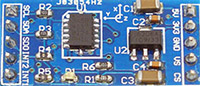
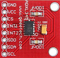
And I also finally got around to posting the drip logger script for this platform on the project’s Github. Even though the drip sensors only use an ADXL345 (for now), I left in all the other sensor support developed for the flow monitors, as the system is meant to be easily adapted to other applications. I also have two different versions of sleep code buried in there, one with the Rocket Scream low power library, which shuts off the BOD, and the other which just uses a variable WDT timer to wake from sleeps while the fuses are left on. I still have not decided if I am comfortable with BOD fuse shutdown in a data logger application. With a 10k limiter keeping the led current low, I sometimes leave the indicator pips on during sleeps without impacting the power budget too much. If you change the limiter to make the led brighter, make sure you shorten the time that the led is left on.

From the beginning I have focused on creating a fully functional data acquisition system from a small number of preexisting modules. Only interchangeable, non-proprietary components and formats are being used (AA batteries, csv files, SD cards, etc.) because I want my logger to have the flexibility of replacing any individual component with half a dozen other parts that are readily available.  To give some sense of this, I have compiled a “budget” and a “preferred” parts list:

Budget Parts:

Component Comment Cost

CloneBoard
*Clones work, but the “real” Sparkfun ProMini boards give me trouble with the SD cards. I suspect that a 22uF  decoupling cap between the SD card’s Vcc<->Gnd  lines might help the MIC5205 cover the current peaks.

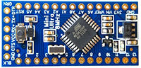
3.3v ProMini clone*: And occasionally you catch them for <$2.50 on eBay. Make sure Vreg is 150mA or more, and watch for Vcc> 3.3v.  Usually 0.05-0.2 mA > sleep currents than Rocket Ultra boards, pin layouts can be irritating, remove power leds & inspect solder joints very carefully. It’s worth noting that you can  bypass the onboard regulator, and use an external MCP1700 vreg. $4.00 (+guilt)
RTC board RTC modules: wash them as they are often covered with blobs of leftover flux, remove charging circuit & pwr led resistors. Check my RTC page for further info on these modules. $1.50
 flipupAdapter Micro SD card adapter: try to get the ones that have Molex connectors, you need to leave room for the flap in your design, or you could try the self-spring type but these don’t seem to hold up to the soldering heat as well. If you hear a “snap” during soldering,  start over – you killed one of the spring contacts. $1.00
 cheepbatholder 
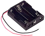
3 x AA Battery Holders:  and don’t forget the connectors! I usually go for the deans style knock-offs,  but expect to throw more than a few of them out due to bad alignment. You need a good soldering iron to use them. $1.50
 3_colorled 
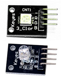
3 color LED module:  The old round-style Keyes modules are the brightest I have found so far with a 10k limiter. You could buy raw common cathode leds for less, but I find the little breakout boards make it easier to mount them with JB plastiweld putty $1.00
 plasticbox 
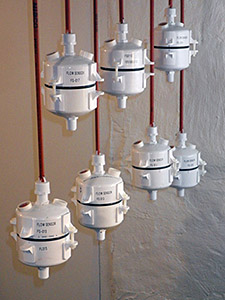
There are so many different pre-built waterproof boxes out there to choose from I’ve lost count. If you build your own from PVC, you can make them far more rugged. $3.00
The first time I deliberately purchased something with DRM. The Muve Music cards are the only ones I have found that are usually authentic when I get them on eBay. My longest logger runs to date (5 months) have generated less than 50Mb of CSV data. So 1 gig is plenty. Test your SD cards extensively before any deployment to make sure they go to sleep properly! $2.00
 cp202 
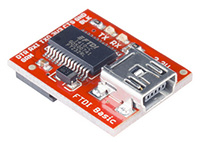
You will need at least one serial adapter, and I usually bring several for fieldwork. CP202’s are cheap but don’t work as well for me as FTDI’s. Be sure to get 3.3v and note that Windows drivers will brick fake FTDI’s $2.50
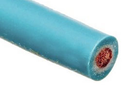
Adafruit sells 26awg silicone wire in 2m lengths. Perfect for starting a new project without breaking the bank. Deans micro plugs are the best connectors I have found and they are available from 2 to 6 pins. Resistors, wires, heat shrink, etc. The cheapest stuff I have found so far is at Electrodragon, but you get what you pay for wrt quality & 3 week  delivery times. $1.00

Preferred Parts:

When the budget isn’t too tight, I splash out for better components. After you build a few, and go through the effort to install them, you will start to realize that your time is worth more. Certainly your data is. But I would still make your first few builds with cheaper stuff, at least till you feel confident putting them together. Cable routing inside a housing is important, and it usually takes me a few tries before I get the physical build sorted out.

Component Comment Cost
miniultra The Rocket Scream Mini Ultra wins over other mini format boards with lower sleep current & 100 mA more juice at the high end. I also like the layout, which has an extra ground pin available for the voltage divider. 1284P’s like the Moteino MEGA (+built in RF!) are looking interesting, but I have not had a chance to play with them yet. $14.00
chronodot The Chronodot is still my gold standard as a trustworthy RTC. But using it takes more space, and requires a separate EEprom. Of course that allows you to go up to a 256k  AT24C256  possibly eliminating  the SD card. Or try a little FRAM for faster writes. And for only $33 more you could go all the way to a FE-5680A atomic clock but good luck fitting that into your housing 🙂 $17.00
 adafruitmicrosd I trust Adafruit’s quality control.  This board lets me tuck the SD under the RTC in tight builds if I use 15mm M2 standoffs.  $2.50
 BatteryHolders 
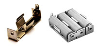
Battery holders:  Heavy duty aluminum holders from Keystone Electronics are my 1st choice. 3xAA 147’s are good, but singles give you more layout options. Don’t forget isolation diodes if you have multiple banks. $4.00
 Pololu I’m putting the Pololu Pushbutton Power switch in the “preferred” list because it’s not required and it adds 0.3 mA to the sleep current – that’s more than the logger itself! $6.00
 platform parts
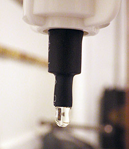
The rubber flexes quite a bit under water and I have only tested these caps to about 5 m depth.
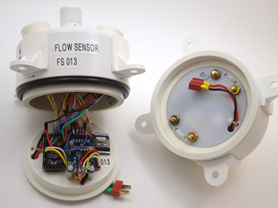
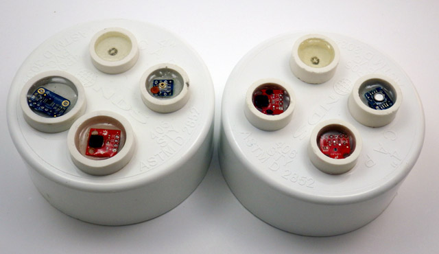
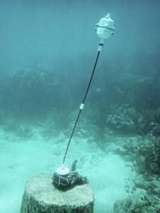
Waterproof Housing: 4″ PVC sewer drain cap, 4′ knockout cap to mount logger components inside & a Fernco Qwick Cap. I mount the LEDs & sensors in short lengths of 3/4 pipe which are solvent welded to the exterior, then filled with Loctite E30CL $6.00
 JY-MCU 
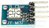
I like these tiny JY-MCU ‘s when I have a design that is really tight on space. But getting a particular 5050 is not easy on eBay due to unreliable vendors. $1.50
 wire1 
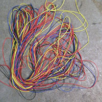
My current favorite wire is Adafruit’s 26awg with Turnigy silicone & Cal Test Electronics Test Lead Wire also being good. Stiff PVC insulation gets irritating when you are trying to route wires into small housings. $2.00
 GroveHub Most of my builds go under water, so the sensors get potted into place on the housing. An interconnect system like the I2C hub from Groove Studios makes the “sensor caps” interchangeable. $3.00
 Sparkfunftdi These Sparkfuns are still my favorite serial adapters, they always seem to work, and the new pin connectors work are more robust. $15.00

Well, there it is: the simplest fully capable datalogger I could come up with. You have from 3 to 5 analog lines free depending on your board (1024 levels on the ADC), and two digital lines left for your 1-Wire sensors (and you still have a free interrupt line on pin 3, and the analog pins can be used identically to the digital pins, using the aliases A0, A1, etc) . I2C is already pulled-up (4.7k) & broken out for you on the RTC cascade port. SPI is still available if you watch your timing with the SD communication. (Both get SCK, MISO, and MOSI in parallel, But each device needs its own Chip Select line, as you can only communicate with one device at a time : SoftwareSPI is also an option but it looses the speed advantage). If you need better resolution on your ADC, you can add an ADS1015 to add four more 12 bit channels. If you need more output lines, you can look into adding a shift register, and there are plenty of transistor/relay breakouts if you want to control high power loads or LEDs.

Once you have a unit up and running, don’t forget to give the boards (but not the μSD adapter) a good dash of silicone conformal coating before they go into the field. And it never hurts to throw a desiccant pack or two in there while you are at it.

——————————————————————————————–

Addendum 2014-10-09:

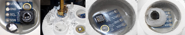
I tested two breadboard builds (configured as drip sensors) to get a sense of the current draw of the individual components. Without the power switch, the ProMini clone logger drew a sleep current of 0.26 mA sleeping in powerdown mode using RocketScreams Low Power Library with ADC & BOD off.

ProMini clone +
Adxl345 accelerometer (50 hz, power save mode) :  
                          0.058 mA
Sandisk 256mb uSD card :                                                                         0.061 mA
DS3231 & AT24c32 eeprom combo  (with 4.7k pullups) :                   0.089 mA*

* I also tested an AT24c256 separately with a chronodot RTC, 10k pullups, and that eeprom draws about 0.03 mA when not being accessed. As you might imagine, I will be examining the RTC very carefully, as 0.089 mA is much higher than I would have expected for something that is supposed to run off of a coin cell. (The datasheet actually specifies a standby supply current of 0.11 mA at 3.3v)

Double lenth header pins make it easier to breadboard the SD card.

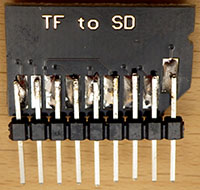
Double length header pins make it easier to breadboard the SD card.  DO NOT TAKE TOO LONG to solder jumpers onto any of these adapter boards. If the springs mounted inside re-flow from excess heat, the connections are toast.

Subtracting those figures from 0.26 mA indicates that the ProMini clone with its MIC5205 regulator uses about 0.052 mA when the unit is sleeping. I am guessing that most of that is due to losses on the regulator, since it is still providing power to the above components. 

Then I changed over to a RocketScream Ultra board, and the whole logger drew 0.22 mA with the same SD card, indicating that “sleeping” logger overhead with their MCP1700 regulator is around 0.012 mA. Significantly better than the 5205 based system, and you have another 100 mA of current capacity at the top end.

I then tested that Rocket ultra unit with the Pololu power switch in the circuit, and sleep current went up to 0.53 mA , indicating that the switch is adding 0.32 mA to the sleep current for this design (after I removed it’s power on LED). Just to be sure about this I measured the current on the other side of the Pololu switch, and the logger unit was still drawing 0.22 mA, so it was not noise, or some other weird side effect keeping the SD card from sleeping properly.

Addendum 2014-11-28

A month long test of one of these units binning at 15 minute intervals, with the Pololu installed (0.56mA sleep current) lowered the 3xAA power supply voltage by 181 mV.  Being conservative, this means we will only get about 4 months of run time with the no-name alkaline batteries I used. That’s a pretty dramatic reduction of run time for that one extra component so I probably will not be using the Pololu switch for my longer term deployments. Field test results so far indicate that a unit sleeping at 0.30 mA will deliver between 6-9 months of operation on a 3xAA battery pack.

Addendum 2015-01-20

Soldering Pullups and Jumpers on SD card adapter
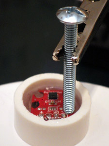
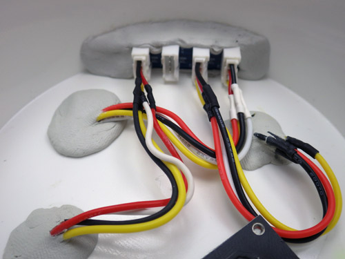
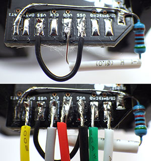
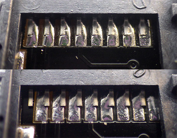
Just thought I would post a quick shot of how I jumper the pullup on that SD card adapter with the legs of the resistor itself. Super thin 30 AWG wire makes jumpering the ground line much easier as well. Once all the jumpers are on, I clean off leftover flux with 90% isopropl alcohol, and then coat the contacts with silicone conformal coating, being careful not to let it run to the other side of the board where it would block the connections. Then I adhere the boards to the platform with double sided tape, which has been working surprisingly well on ABS knockout caps.


Two resistors on ledsIt is also worth mentioning that the Green channel on the multi color common cathode LED’s is so much brighter than the red & blue colors (4000mcd vs 8-900 mcd), that you can actually use two limiting resistors – one 10K on the common ground line, and an extra 20K on the green line.  In fact, if you can live with a really faint indicator led, you can take the limiters to 20/40K or more if your LED is bright enough.  You don’t want to waste too much power on indicator LEDs when no one is around to see them, and this brings the green channel down to 110uA, while leaving the red & blue channels bright enough to see.  Luke Miller has an elegant method using a magnetic reed switch interrupt to enable & disable his status LED’s to save power, but I often need all the interrupt lines for my sensors.  I could probably work around this with a pin-change driven interrupt, but have not had a chance to dig into that yet.

Addendum 2015-02-12 

I just wanted to add a link here to my new pvc housing design. While not quite as simple as the rubber quick cap housing pictured in the table above, I am certain that this Formufit table-cap based design is the simplest diy housing you could build that will go to significant depth under water.

Addendum 2015-04-14

On my logger I use a voltage divider to monitor the main battery. This bleeds a few μA, but given the overall sleep current that’s a small price to pay for the simplicity of using two resistors & a cap to do the job.  However I just stumbled across a very good way to monitor the battery voltage with virtually no loss over at the LowPowerLab blog. About half way down the discussion user JC suggests ” a resistor divider network, with the high side gated by a FET. Turn the FET on when you want to read the battery voltage, off the rest of the time. The leakage is somewhere down in the femtoamps.”  Another elegant solution for me to look into if I ever get this project to the stage where I am actually implementing elegant solutions.

Addendum 2015-06-28

It will be a while before I sort out all the details of the V3 logger platform, but for a preview of what might be coming,  you can see a couple of builds currently on the test bench here. Also, after many successful field deployments without the power switch where the batteries died but the SD card data was still intact, I have dropped the Pololu power switch from the design. I just could not afford to loose all that power.

Addendum 2015-10-24 

I have produced a set of detailed build instructions for a pro-mini based version of this data logger which can be found at:  

  • Part 1 (component preparation)
  • Part 2 (logger platform assembly)
  • Part 3 (housing assembly)

I still prefer to use the rocket ultra as it’s voltage regulator is more efficient, but it is still possible to build a decent logger with the minis that should sleep below 0.25mA.

Addendum 2016-01-25:

Reliable sources recommend pullups on the SPI lines, though I have been running my loggers for a long time without them.  I have noticed that some SD cards take a really long time to go to sleep unless CS, MOSI & MISO are pulled up, and some just refuse to sleep at all without the pullups. These weak pullup resistors are not described in this tutorial. If you already have loggers built without them, there is a workaround using the 328’s internal pull-up resistors that I current have in testing.  Despite the fact that only CS requires it, I found that all three lines had to be pulled up before misbehaving cards went to sleep properly. So add these lines to the beginning of your setup before you run sd.begin

// pulling up the SPI lines
pinMode(chipSelect, OUTPUT); digitalWrite(chipSelect, HIGH); //pullup the CS pin
pinMode(MOSIpin, OUTPUT); digitalWrite(MOSIpin, HIGH);//pullup the MOSI pin
pinMode(MISOpin, INPUT); digitalWrite(MISOpin, HIGH); //pullup the MISO pin
delay(1);

  It’s worth noting that there is some debate about the utility of this approach. Because SPI is a complex protocol, adding internal or external pullups could actually prevent you from being able to use other SPI sensors with your data logger. That is one reason why I tend to stick to I2C & analog sensors on my builds, so the SPI lines are dedicated to the SD card only.

What to expect buying cheap electronic components from eBay & AliExpress

The first time I deliberately purchased something with DRM.

The first time I ever intentionally purchased something with DRM on it. But for me, 1 gig is plenty of space! With Sandisks wear leveling, and a 1 million hour MTBF, (yeah…right…)  I am hoping that a few years in someones cell phone before I get them won’t matter. About 10% of these used cards fail to pass my low current sleep tests, and since they only cost $2, I just throw those away.

After playing the SD card shell game for the last week, I think I have finally found a way to make sure that I have authentic Sandisk cards for my data loggers. Muve music microSD cards were custom built by Sandisk for Crickets music service, and they put some kind of blocking routine into them that prevents you from seeing 3/4 of the space on the card. As you might imagine, extra custom circuitry which makes a product less functional affects its market value, so they are unlikely to be seen as a profitable target by counterfeiters.  Of course I put these used cards through a full test routine, formatting them with SDformater, and then making them sweat through a good bout of H2testw’s verify. And even though what I am after is stable low sleep current, I keep an eye on the meter during the testing. Some of the fake cards I ran into earlier draw unusually large amounts of power during write operations, even if they sleep OK.

More adventures in eBay land:

Going through all that motivated me to make a post on the approximate nature of buying cheap electronic components on the internet. Of course there are warnings about this all over the place. But when I was just starting out, very few people took the time to provide details so I had to learn this from scratch.  The easiest way to convey this is with a table showing the photo from the listings  vs  what actually shows up in the mail somewhere between 2 & 8 weeks later. I would say the current hit rate for actually getting what I thought I was ordering from vendors outside the U.S. is about 60%. The rest of the time you get something that resembles the item in the listing…more or less:

Photo Shown Typical substitutions Comment
Square boards have 4 mounting holes, important in tight spaces. roundBoardRTC Don’t count on fine details like mounting holes or board dimensions matching the listing. Batteries can be missing -or- Cr2032 -or LIR2032,  no matter what is shown in the photos.
JY-MCULow profile 3 color & quite visible with 10k limiters. Brightness is highly variable in eBay 5050s. 2 Other leds …or one of 5 other types randomly intermixed on same order. Sometimes they have limiters, sometimes they don’t. Silk screen labels almost never match the actual pin colors indicating defective runs.
MolexBoard flipup If you get the Molex connectors they both work well enough, but if you don’t have the overhead in your build for the flip up style, it’s kind of annoying to get them.

I could go on, but hopefully that gives you a general idea. And this is in no way limited to eBay. But these kind of replacements are usually not hard to work around, and since the parts only cost a buck or two, I’ll make parallel orders from other vendors, just to be sure I get something I can work with. Order different quantities from each vendor when you do simultaneous orders, because the parts could arrive weeks later, and there will be nothing written on the package in English to help you figure out which vendor sent which shipment.  Always do a “test” order of a small quantity, before ordering multiple units from an eBay vendor, and don’t be surprised if the product changes like this from one batch to the next anyway.

More concerning are part substitutions directly on the boards.  The more components on a breakout, the higher the chance that at least one of them will not be what they claim it is. Complex combinations like you see on IMU’s are a red flag:

Photo Shown Comment
IMU GY-81-3205 10DOF IMU modules are usually described as having the a 1g BMA180 accelerometer (which I use with the HMC5883L in the flow meters) but from places like Miniinthebox, Gearbest, Amazon, etc. they actually ship with crappy 2g BMA020 on board. Of 5 vendors I tried, only NYplatform actually sent this board with a BMA180.

If I’m rooting around on eBay for a sensor board to try out, I get one with as few components as possible. For example, I use the ADXL345 in my drip sensors. These things are common as dirt, and almost as cheap, but the boards are often laden with dubious quality voltage regulators, power LEDs, etc.  In general, the less cruft there is, the more likely it is that it will work, and I always look for boards that have a 3.3v power input.

Avoid: Ahh, that’s better…
adxl345-1 adxl345-2 adxl345-3

Of course this is still no guarantee, especially when a conditioning procedure is needed for the sensor to meet spec.  But when the parts are only a couple of bucks, I don’t have worry that much about frying them when I am just noodling around.  (I killed several of these things before I realized it that JB 5-minute plastic epoxy dissolves IC housings before it cures…) And it’s just the magic of eBay economics that you usually pay more, sometimes much more, for the breakouts with fewer parts on them. The other thing to watch out for is chip variant substitution on the same board.  I use a fairly common DS3231 Real-time Clock module on my loggers, but about half the time the chip that arrives on that board is the DS3231-SN and the other half the time it’s the DS3231-M. While similar in overall function, those chips have dramatically different drift characteristics over time. The vendors just play dumb when you complain about showing photos of the better chip, and then shipping modules with the poorer quality one.

Inspect all solder joints. The lower image shows a pretty typical alignment skew on the cheap SD adapters.

Inspect all solder joints. The lower image shows a pretty typical alignment skew on the cheap SD card adapters. Of course I did not discover it until I had already soldered it into place inside one of my loggers . . .

If you paying peanuts for a sensor that normally sells for $20-$30, you should expect a 20-25% failure rate, with about half of those failures being subtle, like for example, one axis on an accelerometer not reading at the same bit depth as the other two, or only reading in the positive, but not negative direction, etc. Always test your cheap sensors against a  a “known good” board and one thing I have found to be particularly diagnostic is how much current an IC draws.  If the milliamps match the data sheet, there is a good chance that the sensor is Ok.  This is especially true of low current modes, as I have run into several cheap sensors that give decent readings, but never go into low current sleep modes. This makes them useless for data logging applications.

It’s usually a much safer bet to get simple passive components on the web, and the difference between low end parts, and brand name stuff is often an order of magnitude or more.  When you are just starting out, finding cheap component kits can get you rolling for without breaking the bank (although the thin wires & non standard labeling will eventually get on your nerves) Sadly, I did not find out about those until I had already paid extortionate amounts to radio$hack, etc.

I was most of the way through the bundle by this point, but by then I was angry enough to take a photo of it.

I was most of the way through the bundle by this point, but by then I was angry enough to take a photo of it.

And speaking of places where staff react like I a speaking another language if I use the words like “capacitor” in conversation,  I have to add that it really does make a difference if  you order stuff from a vendor who actually uses the products they are selling.  For example, I recently ordered a large amount of wire from HobbyKing. Not only did they take quite a while to ship it to me from their US warehouse (for items listed as “in stock” when ordered) but they looped the many different types of wires into a single large intertwined bundle. It took ages to untangle that mess, leaving me with the impression that they are just a warehouse operation, charging a markup simply to repackage stuff that they too are ordering from China.

Everything gets a bath in 90% isopropl alcohol to remove flux residue.

Everything gets a bath in 90% isopropl alcohol to remove flux residue.

I guess that if I was to sum it all up, I’d say I still get lots of stuff from dodgy online vendors if I am risking $5 or less. The more expensive an item is, the more likely I am to go upmarket to a vendor like Sparkfun or Pololu.  For example, when I need a tool like a soldering iron, or a multimeter, I check what they reccomended at EEVblog, then I see what they think about it on Adafruit.  Those guys really know their stuff, and I never have to worry about dropping a couple of hundred bucks on their recommendation. (something I would never do with an eBay vendor from Hong Kong)

Anyway, I hope that helps someone out there who is just getting started (like I was not so long ago). Even with the best research beforehand, I still end up wasting about 30% of the money I spend on components, because there are alot of elements to any item that one just has see & use to understand. And there is always seems to be some “physical” factor that the experts thought was too obvious to mention, that dramatically affects your particular project… like… for instance…never putting your coffee down on the work bench beside your newly built data logger 😉

High SD card sleep-currents from counterfeit cards & floating pins

Time for some head-to-head comparison testing.

Wait…do I hear something?

The more I thought about it, the more the high power drain of the flow sensors got under my skin. How had I misjudged the performance that badly, after so many successful bench top tests? I was determined to get to the bottom of this mystery.  The simplicity of the “one sensor” drip loggers, which spend all of their time in sleep mode, meant I had a tool I could use for some process of elimination trials. So I made a few loggers that were identical except for the mcu and put them on my newly arrived µCurrent. But my initial results were all over the place. Some units slept at a nice comfortable 0.2 -0.3 mA, while others drew about 2mA, and a few pulled 5mA or more.

Mcu: Configuration: I(sleep)
Rocket Ultra 128mb SD , adxl345, LED, 2×4.7 MΩ divider 0.26 mA
Sparkfun ProMini 256mb SD , adxl345, LED, 2×4.7 MΩ divider 0.35 mA
Cheap Clone 256mb SD , adxl345, LED, 2×1.0 MΩ divider 4.66 mA
Tiny Duino 128mb SD & shield,LED *Bma250, 5883L, DS18B20 5.42 mA

That last one is my spare flow sensor, and it came in around 5 mA , apparently confirming the high power use seen in the latest field deployment data.

But five milliamp! Was that thing even sleeping at all? I started wondering if adoption of the Rocket Scream sleep library meant that some of the boards were not sleeping properly, so I dug up the older non-RS code and ran those…nearly the same results, with about 0.03 mA more current because because I was not shutting down the BOD in the older sleep routines. But that small consistent difference told me that the units actually were going into sleep mode between sensor readings, so I went back to my original thought that voltage regulators were my energy vampires.

Then, as I was juggling things around, I switched an “apparently identical” 128mb Sandisk microSD card from the Rocket Scream unit into the TinyDuino flow sensor. And suddenly it dropped from an abysmal 5 mA sleep current down to less than one milli-amp.  A furious shell game followed and after locating the “best” 128mb microSD card, and using it (and the same battery module) the test units delivered:

Mcu: Configuration: I(sleep)
Rocket Ultra 128mb SD , adxl345, LED, 2×4.7 MΩ divider 0.24 mA
Sparkfun ProMini 128mb SD , adxl345, LED, 2×4.7 MΩ divider 0.27 mA
Cheap Clone 128mb SD , adxl345, LED, 2×1.0 MΩ divider 0.30 mA
TinyDuino 128mb SD & shield , LED *Bma250, 5883L, DS18B20 0.90 mA

So counterfeit SD cards were causing the high sleeping currents!

Looks like I have been sold several batches of bad cards from eBay, which do not go into the low current sleep mode I was expecting from the Sandisk spec sheets! (typically around 0.15 mA (see sect2)) When I tested each of the cards I have on hand, the Rocket loggers gave me sleep currents ranging from 0.24 to >5mA, with a cluster around 2mA, and another around 4-5mA.  This does not seem to be related to whether the card is 64, 128 or 256 mb.  I don’t see really bad screen printing but there are differences between cards with the same branding. To be honest, I figured that these small cards are so old, and worth so little money that nobody would bother cloning them. I was wrong.

At least I have identified the issue, so the shield regulators in the Tinyduino stack are off the hook for the bad power performance of my field units. The only problem with this new information is that I am fairly certain I put a bunch of crummy cards into the newly built loggers that we just deployed.  With six AA’s, the flow sensors should survive all right, but with excess current drain like that, the drip sensors will expire after a couple of months. (and likely go into some kind of weird brown-out power cycle loop until the sd cards are toast…)

Addendum 2014-09-22

If I can’t locate a reliable source for small low sleep current SD cards, I will look into Solarduino’s solution of putting an N-MOSFET on the ground line. A few folks have pointed out that might not be quite as easy as it sounds to turn the power to an SD card on and off like that: “because SD.h wrapper for SdFat has a bug that prevents multiple calls to begin()”. What I really want is a system that protects the data by cutting the power to the SD cards whenever the power supply falls low. I would like this control to latch off (in case there is battery rebound), and use an “independent” circuit that relies on passive components. I have some homework to do there because you obviously can’t pull the plug when you are in the process of actually writing to the SD card. I know from my Vcc logs that the new file creation event is biggest sustained load on the system – making it the thing most likely to trigger the cut-off if the mcu is not in control.

 Addendum 2014-09-24

It looks like some people have managed to test Sandisk microSD cards that sleep down around 70 uA.  If that’s true, then 300 uA sleep currents mean I have other power issues still to sort out on these loggers.  According to fat16lib, SanDisk claims some of their cards draw higher idle current in SPI mode if the unused pins are not pulled high: 

“The ‘RSV’ pins are floating inputs. It is the responsibility of the host designer to connect external pullup resistors to those lines. Otherwise non-expected high current consumption may occur due to the floating inputs.”

Evidently this is a perennial issue for beginners (like me), concisely expressed by MarkT over at the Arduino forum:

“This is the classic floating-inputs problem with CMOS logic.  Never leave an input pin unconnected.  If you do it can either oscillate or end up at 50% of the supply voltage (at which point both input transistors are conducting).  Either situation increases power consumption drastically (3 to 5 orders of magnitude for a single CMOS gate) compared to the normal static situation.  Now this might be a small fraction of current consumption of a running microcontroller, its going to dominate the sleep-mode consumption when nothing is being clocked.”

So I need to do a few tests to see how this helps lower the sleeping currents on my old small SD cards.

Addendum 2014-09-27

 After testing the 64, 128 & 256 mb cards I bought from eBay, I have found that if you have the “good” SD cards, the Rocket based loggers generally gravitates towards 0.2 mA or less, even if connections 8 & 9 are floating.

However many of my cards do need pullups (0r pulldown) resistors on the two data connections that are not used for SPI to keep them from floating, or the sleep currents are much higher. In the forums (and the datasheets) people seem to be recommending 50-100K pullups. I tested about 50 cards, and general result is: If this logger system+Sd card sleeps around 0.22mA with the pins floating, I already have a “good” card and pullups won’t change the sleep current by much. However about 1/2 the time a pulldown increases the sleep current of a low power sleeper, sometimes adding as much as 0.6mA (so total sleep current goes to about 1 mA). If there is no rise, then sleep current is unaffected by the pulldown.

If my system draws between 0.5 mA to 2mA with the two pins floating…then a pull down resistor on those two lines will usually brings the whole system down to about 0.25-0.35 mA sleeping current. A pullup does not change the sleeping current of these bad cards quite as much, usually reducing sleep currents by about 1/3-1/2 as much as a pull down.  So preventing the pins from floating is always good to reduce sleep current, but the worse a card is when pins 8&9 are floating, the more likely it is that pulldown will help it more than a pullup on those lines. This is very odd because no where in the data sheets does it specify to use a pulldown resistor. 

I am setting my pass/fail point for the entire logger at 0.33 mA, and if I don’t get to or below that with either pullup or pulldown, then I’m calling it a bad card and I won’t use it.  If the “sleeping system” current for this logger design is above 2 mA with pullup/down, then I have a REALLY bad counterfeit microSD card, and I just throw it in the rubbish bin (which happened to about 6 out of 50).

The WORST cards of all bounce down to a reasonably low sleep current when the system first goes to sleep, and then slowly increase over the course of 2-5 minutes, as I am watching the meter, even though the logger is completely asleep.  Those cards seem to “creep up”, whether I put a pullup, or a pulldown, on the unused lines. What’s interesting is that they don’t “jump up” like I would expect if they were waking …they just slowly increase the draw bit by bit. Of course I am watching this with a plain old multimeter, so I am only seeing “the average”.  Perhaps its a whole bunch of wake/sleep cycles in some kind of self triggering loop? I found 4-5 of these (of 50) and I am assuming that the card controller itself is NFG. A couple of these eventually went over 5 mA before I lost patience and just pulled the plug, but I might go back and let them run later to see how far they go. It might even be handy to have a duff card like this around when I want to bring the power supplies down to test power fault handling.

Generally, if I have a good card, it goes into sleep state as soon as the MCU sleeps, and you can see that on the meter because the numbers are completely stable right away. The crummy cards seem to wander around for a while, like they have to think about whether they actually want to go to sleep or not. Some keep on jitterbugging, even after they have gone into low sleep current territory. So far, I’d say about 50% of the cards from eBay have been ok, with the ones being sold as “used” being much better than the “new” ones.

Addendum 2015-01-10

Looks like I am not the only one who has had to grapple with SD card power issues.  Luke Miller, over at the Open Wave Height Logger project, spotted another more subtle power problem with some SD cards using his oscilloscope.  The new SD cards that he tested were drawing about 200 uA, which sounds much worse than the 60-70 uA Muve Music SD cards I am been using.  But his loggers operate at an incredibly fast sampling rate, and that means time to sleep is just as important as the actual sleep current. Until I get my hands on an old scope and see for myself, I need to consider the possibility that the cards I am using might not be as good as I think they are….

Addendum 2016-03-29

After experimenting some more with mixtures of hard vs soft pullups (& despite the fact that only CS actually requires it) I found that three lines had to be pulled up (w MISO as INPUT not output!)  before misbehaving cards would sleep properly. So add these lines to the beginning of your setup before you run sd.begin

// pulling up the SPI lines at the start of Setup with 328p’s internal resistors
pinMode([ChipSelect], OUTPUT); digitalWrite([ChipSelect], HIGH); //pullup SD CS pin
pinMode([MOSIpin], OUTPUT); digitalWrite([MOSIpin], HIGH);//pullup the MOSI pin
pinMode([MISOpin], INPUT); digitalWrite([MISOpin], HIGH); //pullup the MISO pin
delay(1);

I found that enabling these three internal 20K pullup resistors raises sleep current by between 1-5 μA, so it should not hurt your power budget too much, and could potentially save far more power by helping the SD cards go to sleep faster.

Addendum 2017-05-21

Well, I finally took the plunge and started cutting power to the SD cards: Switching off SD cards for Low Power Data Logging.   I left that step for last because as I was being cautious about anything that might put my precious data at risk, but so far (and I am still testing it…) is seems to be working OK. While Sandisk 250 512Mb cards are generally the best sleepers when the cards remain powered, testing so far shows that Nokia 256 MB cards have superior handling of the the de-powering & restarts events. (ie: the fewest housekeeping artifacts)

Bench Testing vs. Real world power consumption of our Arduino dataloggers

I finally have a moment to look at the data from the recently retrieved flow meters, and the results are not what I was expecting. This was a five month deployment, with the units operating from March 22, 2014 to August 25, 2014. The three pendulum units had identical data logging hardware consisting of a the Tinyduino, Sd shield, HMC5883L compass & BMA250 accelerometer, with a DS18B20 temp sensor and a 3-color 5050 indicator LED.  These units recorded Vcc using the 328’s internal 1.1 vref trick, and even with the usual caveat about 10% variability there, the flow sensors did not deliver anything like the low power consumption suggested by my dry test runs*:

Units3&4_compare_640

(*One of the pendulums had a NCP1402 voltage regulator on the power module, so I will be ignoring that unit for now although the remaining AA cell voltages from that unit were surprisingly similar to the batteries from other the power modules?)

One key observation is that power consumption was similar in both units although Unit4 was creating three times as much sensor, EEprom & Sd card traffic as Unit3. This becomes more obvious if I project these curves down to 2800 mV, which is my cutoff to prevent unsafe Sd card operations:

Unit4_projection

The vertical lines here represent one month of operation, and Unit 4 (above in orange), which gathered almost 45000 samples in that time,  projects out to another two months of operation.

Unit3_projection

Despite a boost from slightly newer batteries and a longer 15 minute sample interval, the Unit 3 projection (in yellow) has almost exactly the same amount of time left on it’s 6x AA power pack. This would seem to imply to me that the quiescent current draw of my data loggers is far more important than the power used to drive the sensors. If I just do a quick ‘back of the envelope’ here, and I assume that the six AA’s deliver about 2000mA each,  we are burning through 12000 mAh in about 5200 hours (est.at 7 months)  =  2.3 mA average current.  Ouch!

So I went back and looked at the results from my longest bench top test. This was done with a configuration matching units 3&4 above, but racing along with a sensor read every ten seconds for most of the test. I plotted that voltage curve again with one month time indicators added:

BenchTest_against time

Even with ~400 000 sensor read/record cycles it operated for almost four months – more than half of my lifespan projections for unit 3&4 and it was running on only 3 AA batteries. I had assumed that much bus traffic was the biggest load on the system by far, but perhaps it is time for me to re-consider things? The Tinyduino sensors each have a regulator, as does their Sd shield…have I been ignoring the forest for the trees?

We also had a stationary sensor unit on that last deployment, with a single MS5803-02 sensor, recording both temperature and pressure (barometric & water level). I hacked into a TinyCircuits light sensor board to provide the regulation and I2C level shifting needed for the 5803, so that system had one regulator there, and the one for it’s Sd card.  With only two voltage regs, and no power being used by the DS18B20 temp sensor (which draws  for almost 800 ms to load its 12 bit registers), the stationary unit projects out like this:

MS5803_projection

At 11 months this just squeaks back in my  design target of one complete year of operation.

These curves leave me with a couple of impressions:

Any regulator, even one with relatively low quiescent current, will draw at least as much juice over time as any of the bits you are actually powering with it in a long term application like a data logger. I might also need to take another look at the losses on the Shottky diodes isolating the battery banks, because even with all those regulators in play we are no where near spec sheet predictions here.

I needed better acclerometer sensitivity,so the new Cave Pearl builds have the sensors moved away from the main stack, and all of the power for the I2C bus is now runs through the single hacked light sensor board, similar to the stationery unit above.  While power was not my primary reason for doing this, I suspect this was the right way to go for power managment in the overall design.

And finally, the drip sensors have only one single regulator in their build, with the Sd card hanging right off of the pins.  And now I am playing with BOD fuses, probably exposing my precious data to even more hazard.  But it just might be that the humble three component logging platform actually surpasses the TinyDuino logger units, in terms of power use over time.  After some months of waiting, my eevblog µCurrent is finally on it’s way, so I will have more power test results to report soon. In future, I will do my bench tests with two identical units,  one of which will do sensor readings, etc., as normal, while the other one simply sleeps the whole time, so that I can isolate where the power is being used.

Addendum 2015-04-12

There have been quite a few field trials since this test was done, and the short version of the results is: TinyDuinio based loggers draw about 0.065 mA sleep current, which on a 6x AA battery pack will get you between 6-9 months of run time. Loggers built with generic pro-mini style boards draw 0.33 mA which will deliver the same 6-9 months of run time on 3x AA batteries. Having good low sleep current SD card is critical to the success of your data logger and you really need to test to make sure your sensors are going into low current sleep modes as well. Cheap eBay sensors from China often fail this test. 

Field Report 2014-09-02: Our first open water deployment

With the fieldwork coming to a close, we still had three working betas from the March deployment in handThese had already delivered a beautiful time series, and it seemed a shame to bring functional sensors back home when they could be out gathering more data.  So over the last few days Trish and I hatched a plan to conduct another experiment: Why not deploy them out on the open ocean, just to see what what happens? After all we were staying in the CEA dorms, and they have always been keen to support the research…

But this was going to be a real shot in the dark, as the Pearls were designed for the cave flows in the 0-20cm/s range, and the ocean is considerably more rough & tumble than that. After a bit of digging through her reference database, Trish found a write up of an experiment that had been done with acoustic doppler velocity meters at Puerto Morelos; just up the coast. A quick review of that paper gave me some sense of just how tricky it would be to get meaningful data out of my twitchy little accelerometers. While I chewed on that nut, Trish spoke with CEA’s director, who was quite keen on the idea of putting our new instruments in Akumal Bay.

Showing Marco from CEA how the support system works.

Showing Marco how the support system is assembled.    (Photo courtesy Monika Wnuk)

But it only took one look at the surf breaking over the reef to know that wave motion was going to dominate the kinetics. Fine if you are studying wave energy, but not so great if you want to gauge the direction of flow.  How was I going to tease the overall signal out of my little devices while they were being tossed around like that?  In the end I decided to really stretch the time between
accelerometer readings, hoping that my “average reading” would span the shorter frequency wave cycles.  Each sample would consist of thirteen separate accelerometer readings, separated by the maximum watch dog timer delay of 8 seconds, and then I would throw away the extreme high and low values before calculating an arithmetic mean. I was in the process of running tests with these modifications when Trish returned to our dorm room with Gabriel Rivera (from CEA’s water quality program), who told me that the centers director had arranged for a boat and that they already had an installation site in mind which they wanted me to look at. Trish already had a full schedule of work at Rio Secreto, including a public presentation of her cave research (in Spanish), so once again I drafted Monika as our team photographer and we set out for the launch.

Installing the sensor

Installing the sensor on the old buoy anchor (Photo courtesy Monika Wnuk)

The boat headed straight for one of the main reef buoys, and I was a bit concerned that they intended to anchor my delicate little sensors to that heavily chained beast. But once in the water, Marco guided me to an much older cement barrel anchor that was still in place, though it had rusted beyond use as serious anchorage. This was fantastic! We zip-tied the pivot and support rods into place, and returned to the boat for the sensor itself.  A few minutes later we had the sensor in place, but the poor thing was bouncing back and forth like a ping-pong ball. I had to do something to damp down those wild displacements, so I removed about 80 grams of the eternal ballast mass, giving the flow sensor a much stronger vertical restoration force.

Hopefully secure enough from boats, waves and tourists.

Secure enough from boats, waves and, hopefully, tourists.

The unit was in the center of the water column (at about 3m) and despite the roil of the surf above it now seemed to be consistently leaning in the direction of the particles we could see floating by. Our first open water unit had been deployed!

Our boat rental about to expire, and I now knew that I had to alter the ballast on the two remaining units, so we returned to shore for showers and a late lunch. Gabriel and I re-calibrated the last two units in a tide pool, and I gave him the last of our anchors and support rods so they could install the last two sensors after CEA staff had a chance think about other suitable locations.

After that I drove up to Rio Secreto,  making just in time to catch the end of Trish’s presentation. Her talk ended with a gratifying burst enthusiasm from the R.S. staff as we handed the 2 bar pressure sensor over to the science liaison who had been our guide a few days before. She promised to put it into the cave near the drip sensors as soon as she had an opportunity.

So I would be returning home with only one of the 13 units I had brought down, and in total this trip would see 16 different sensors running in the wild.  Brilliant!  Now it’s time for me to start digging into all that data…

<— Click here to continue reading the story—>

Field Report 2014-09-01: Our first “deep” saline installation

I was keen to see if the Pearls were sensitive enough to track the slower deep water circulations and Trish has an ongoing collaboration with some UNAM researchers studying cave organisms in a system called Ox Bel Ha.  With the new build, I was confident that we could push the envelope a bit, so we planned a dive to a deploy the remaining two Cave Pearls in the deeper saline zone of that system. (around 20m)

Did I mention how much I dislike tábanos?

…thirteen…slap!…point…rrrrgh!…seven…

Once again our friend Jeff loaned me some of his dive equipment, and even better, both he and his partner Gosia, were able take a break from their busy instructor schedules to join us for the installation.  Jeff had often offered his services to researchers in the past, and I think my nerdy enthusiasm amused both of them.  As with previous installations, I calibrated the buoyancy of the sensors at the surface with a small hand-held postal scale. Deeper systems tend to have slower flows, so I adjusted the Pearls to only 10 grams negative buoyancy. This was pretty close to the wire for a system at full marine salinity, but with flows down in the 0-5 cm/s range I was hoping for the best sensitivity I could get. With our kit sorted we put in at a rather boggy zero-vis cenote whose large population of mosquitoes & tábanos which the pre-dive checks at the surface a trial, despite the fact that they had already feasted on me while I did the buoyancy calibrations.

I was sad that we had to leave my little waterproof point&shoot at the surface, because it was a beautifully decorated system, with intersecting passages at multiple levels. Three of us followed Trish’s lead out to a nice wide section where we waited patiently on the line while she inspected the cave with her hydro-geologist’s eye. She found a spot, with a roof profile suitable for our bungee anchors, and instructed me to connect three 50cm segments to pivot, putting the meter in the center of the passage, at 22m depth. With the supports connected I returned for the first flow meter, only to make the unwelcome discovery that both of the sensors were now positively buoyant. Arrrgh! I had cut it too close by calibrating to only -10 grams in the fresh water of the cenote! We transferred a couple of five gram ballast washers over from the second unit, but we still had a slow persistent rise to the ceiling. Trish provided a temporary solution by adding a metal dog clip to the support rods, and since we only had the one spare clip, we called the dive with our second flow meter still in the bag.

Despite the buoyancy problem, everyone was happy with the overall simplicity of the installation procedure, and Jeff graciously offered to re-calibrate and install the orphan meter the next time he was in the system (and he wanted his clip back 😉 )With our shortened trip schedule, we took him up on the offer, and after a celebratory cerveza in Tulum, we gratefully left him with all the pieces he would need for the second installation.

<— Click here to continue reading the story—>