Category Archives: Developing a TEMP ℃ chain

A string of underwater temperatures using one-wire DS18b20s

A Simple DIY Underwater Connector System made from plumbing parts

Up to this point, the Cave Pearls have been self-contained units. But this means that the sensors must be mounted directly on the housings, and the batteries must fit inside.  I already have ideas for new sensors that would require me to overcome these two limitations, so I need to address the issue of how to make electrical connections that are not merely IP68 waterproof, but rugged enough to withstand pressure at depth for a year or more.

I wet-sand the ends (indicated by the red arrows) of that nipple with 600 & 800 grit to smooth away any casting seams.

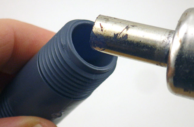
Wet-sand the ends of that nipple (arrows) with 600 & 800 grit to remove any casting seams. Smooth all o-ring seats.

Use a couple of sizes of heat shrink tube to seal the cable to the pex adapter

On 1/2″ barbs, use a couple of sizes of heat shrink to step down (from Ø12/6 tubing) to the diameter of the cable you are using before sealing the connection with epoxy. Adhesive lined tubing  helps the seal. You can also buy 1/2 NPT x 3/8 PEX adapters for thinner cables, but for some reason they cost twice as much as the larger diameter 1/2 x 1/2″ adapters (?) 

As a diver, I had already seen debates about which connectors are the best on the scuba forums, and a quick Google search quickly finds many suppliers for that market. Most of these are “wet-plugable” connectors encased in delrin/rubber, and they are workhorses in many industrial and military applications. High profile companies like Seacon making a bewildering array of solutions, but their cheapest ones come in around twenty five dollars per socket, so a complete connection will set you back at least $50.


Remove the cone washer before filling adapter with epoxy

Remove the cone washer before filling with epoxy. I score the inside of these 1/2″ barbs with an old 8×125 tap to promote epoxy bonding.

Many of these commercial connectors are rated for deep ocean deployments, able to withstand thousands of psi – far more than I will subject them to in the shallow cave systems. And they often give you a short little pig-tail under the assumption that you will be using it with a cable gland , or a bulkhead connector on a nearby housing ( or at the very least a couple of layers of marine grade adhesive lined heat shrink tubing)  I needed some decent cable runs so I went looking for other applications with longer lines at shallower depths . The pool & underwater lighting folks often use  Bulgin electrical connectors, and the 400 series   Buckaneers  (rated to 10m) occasionally come up on eBay in the $10 range, But again you need to buy two sockets (male&female), and you need to buy the pins which are sold separately. So you still end up around $25 per connection.


Make sure your wires are long enough to extend past the nipple, or you wont be able to make the connection!

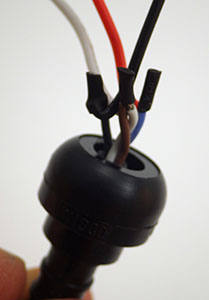
Make sure your wires extend all the way through the nipple, or you can’t make the connection! And use soft flexible silicone wires so they fold back into the connector easily.

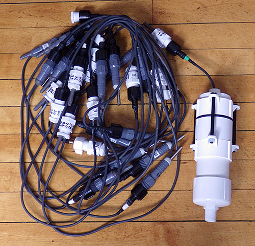
With all that as background, I went hunting once again through the plumbing section at the local hardware store.  I reasoned that anything that could hold water in, could also hold water out, right?  And I think I have come up with a solution using Nibco pex swivel adapters that is pretty cheap and can be adapted to many different applications. These plumbing adapters are rated to withstand 100 psi, which is roughly equivalent to 230 feet under water.  And that is pressure from the inside out, so my gut feeling is that these things will be able to withstand slightly greater pressure in the other direction, where the forces act to increase the compression of the cone washer.  The thing I like about the swivel adapter mechanism is that it applies pressure to a hard plastic lip on the other side of the washer, so as you tighten the nut there is no rotational force being applied to the parts forming the water tight seal.

And it even looks good!

~$6 for parts, and it looks good too.

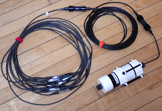
These adapters come in a variety of larger & smaller diameters allowing you to use different cable thicknesses, and you can change the length of the pvc riser pipe in the middle to make more space for the internal connectors. This also gives you a way to adjust the amount of air/buoyancy along the run and with a string of connectors this might be a good way to reduce strain on the cable.  I suspect that the schedule 80 tubes in the middle are the weakest point in the system, but filling the internal space with mineral oil would get these connectors to significant depth, as would a filling of paraffin wax, though that would have to be heated again to undo the joint. 

Addendum

TheSimplestDIYUnderwaterConnector

Don’t forget to smooth the seat on that male hose barb side if it has bad casting seams. You want that connection to be as clean as possible. You need to use small connectors for this M-F design.

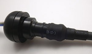
After building a few of these, I realized that it was possible to make them even simpler if the electrical connectors were small enough.  In the picture here, one side has a Nibco PEX swivel adapter, while the other has a male thread NPT to PEX  adapter. These are both polymer, though it is hard to find an epoxy that will bond to it with an applicator fine enough to put the adhesive into the barb cavity. These fittings are also available in brass for the same price, and the o-ring seats are much cleaner on those than the polymer adapters because there are casting seams on the plastic parts. But I don’t know how well the brass will fare in marine environments. Some of my sensors have stainless shells, so I worry about galvanic effects in salt water?  

After this, pull the cable through so the

Pull these joins into the connector so they are embedded in the epoxy.

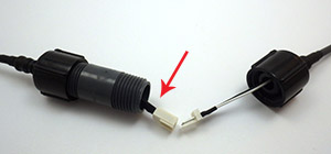
In the photo above I’ve used a three wire PC fan connector, and it “just barely” fits inside the cavity of that m/m hose barb. I will use smaller JST connectors in future, or perhaps Dean’s Micro 3pin or 4pin for something more robust.  The internal diameter of the 1/2 pipe is a little over 12mm, so if you need to squeeze more connections in there you could try a couple of “mini micro” JST’s, but I find that soldering all those wires so close together is a bit irritating because it’s easy to accidentally melt the plastic, loosening the tiny pins. 

I also found that the wire inside my cables were too stiff to fold neatly into this much smaller space, so I had to add some flexible 26 AWG silicone wires to the ends. After the jumpers are attached, pull the cable through so that the solder joins get embedded in the epoxy. This has the added benefit of providing a break in the insulation around the wires, so that if you do get a cut in the cable, water can’t work it’s way through the connector by wicking along the copper strands.  I am still hunting for a good supplier of multi-conductor 22-24 awg cable that has a good “handling weight” for underwater applications. It’s hard to shop for something on the internet when what you are really after is something that “feels right” when you hold it in your hands.

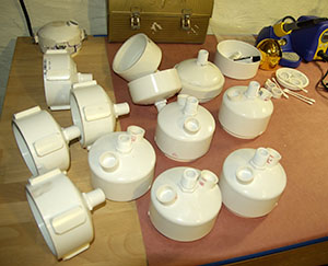
A dual connection cap for one of our 2″ underwater housings. We now use harder PUR sheath cables because softer silicone jackets were too easily damaged during deployment dives. For a less expensive option,  Luke Miller has had success using USB cables with his underwater sensors.  A 3/4″ adapter from the pex connector system gives you a way to mount pressure sensors under oil.

I should add the usual provisos here about this being another of my completely experimental ideas so use this at your own risk.  Pex tubing is generally rated to  ~100psi (at temperatures below 74°F) and if the o-rings can withstand that then they should “theoretically” be good to about 60m depth. Translating that into the real world, I expect these connectors to be trustworthy to about 40m, which covers most of our cave deployments.

Addendum 2015-01-30

I just stumbled across a different solution to the expensive underwater connector problem. His method for waterproofing connectors using 3D printed silicone molds is beyond my current capabilities, but its nice to see it explained with such clear documentation.

Addendum 2015-02-01

If those pex adapters don’t have enough room for your cables, I found another great underwater connector project which might do the job for ya 😉

Addendum 2017-01-23

As time goes on I am reducing the number of interconnects, but even with longer chain segments I will probably stick with only 24 sensors per logger.

As time goes on I am reducing the number of interconnects, but even with longer chain segments I will probably stick with only 24 sensors per logger.

Just though I should add an update to mention that quite a few of these connectors have been in service for more than a year on temperature chain deployments. None of them have failed on relatively shallow deployments from 5-15m depth. The only problem I’ve had  is the length of the connector itself can be challenging when you are trying to pack one of those long strings into the mesh bag for an underwater deployment.


Addendum 2018-12-05

I’ve posted a video showing how I build those underwater connectors and use them with epoxy potted sensors:   ( part of our 2017 screw terminal logger series) 

It’s also worth mentioning that you can improve the fit of various parts by taking advantage of the fact that they are thermoplastics:

Rotate & heat the inside corner edge of the tube until ~ 0.5mm of the material ‘softens back’. Don’t over-do it! you don’t want to alter the tube diameter or hurt the threads.

Quickly press the mating o-ring onto the seat while the PVC is still soft enough to conform to the shape.


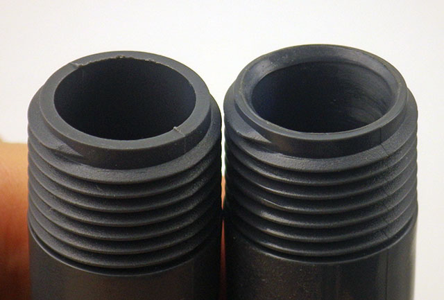
Before & After heat treatment: the o-rings now form a better seal. This is faster than sanding away any rough casting seams on the parts

Addendum 2020-04-06

These connectors & sensor mounts are part of the housing system we’ve been developing since 2015. You can see the latest underwater housing build @ DIY data-logger Housing from PVC parts

Using a DS18B20 Temperature Sensor “without” a dedicated Arduino library

New housings in production

New housings in production. The sensor wells on top will be filled with epoxy to seal the hull.  Note: some of these housings have unnecessary “chunks” of PVC on the outside, as I made them for latch clamps which I am no longer using in the design.

I haven’t had time to post to the blog lately, as I am now in full-on production mode: trying to get five full units running for deployment next week.  Between all the cutting and sanding of the new underwater housings, I have been investigating sensors, and thinking about how to make the entire unit modular enough to allow quick field repairs.  The I2C bus architecture becomes very attractive here, because so many sensors are available for it, and I found a nifty I2C hub from Seed studios, which gives me a standard plug for connectivity. But most of the sensors I found want a steady 3.3 volt supply, and that is not available on the Tiny Duino  (the lack of a 3.3v rail is a weakness of the platform but I was the one who wanted to run with no voltage regulator in the first place..) So I started designing a power supply module around a NCP1402-3.3V Step-Up Breakout from Sparkfun.  I knew this was going to waste 25% of my power for this deployment, but I figured I could use lithium AA’s to make up for the loss, and look around for a more efficient voltage regulator later.

No luck with the voltage regulator even though it seemed to be working fine...

It seemed to be working fine…

Well, a frustrating day or two later and I still had no joy from the 3.3v regulator. I don’t know if it was an inrush current brownout, or transient spikes, or output ripple…but for some reason the tiny stack simply will not run from this regulator – all I get is one little pip out of the on-board led and that’s it.  Grrr! There goes about half of sensors I planned to use with the nice I2C breakout boards I had just purchased, unless I can somehow power the sensors “separately” from the main mcu stack. (And there is no guarantee I won’t have the same kind of gremlins pestering me there…)

Time to make lemonade: I had a few DS18B20 one wire temperature sensors, and they are not too choosy about input voltage, so I figured I would give them a try, while just running the Tiny’s from unregulated AA’s (…again).  DS18B20’s are common as dirt, and almost as cheap, and there are libraries for them everywhere. So it should not take long to get them going…right?

Well what I thought was going to take me 30 minutes has actually taken me a day of digging to sort out, so I am posting the result here, to hopefully save someone else the trouble.  The standard approach is to install a Dallas control library, and a one wire library to run this sensor. Most sources suggested the library written by Miles Burton, and the one wire library over at PJRC.  And after a few grumbles, like finding out that zip file created directories with the wrong names  ( “dallas-temperature-control” from the zip extraction needs to be renamed to “DallasTemperature” for it to work) I did get the test code running…sort of. Now don’t get me wrong, Miles Burton has created a veritable swiss army knife of a library, but a tiny script for this one sensor weighed in at 8,772 bytes. That’s almost a third of the available program memory, and I already knew my data logger script was around 22 k (with accelerometer) , so that was not going to leave much space for the other sensors I want to add.

Logger units with I2C hub for sensor and RTC connections.

Logger units with I2C hub for sensor and RTC connections.

And while I was sorting all that out, I discovered another problem with the DS18b20: Every once and a while it was throwing out a spurious reading of 85 degrees, but it was frustratingly intermittent. More run tests with different settings showed that the error never happened when I had the sensor set to run at 9-bit, but it popped up more frequently as I raised the bit depth. Back to digging through the forums, which revealed that this is a pretty common issue with the DS18b20. The “default” setting of the registers produces the 85, which is what you get if you read the sensor too soon after a reset. If you sift through the datasheet, you find that when you ask the sensor for the full 12 bits of resolution, you need to wait at least 750 ms for the sensor to embed the temperature data in it’s eeprom before you can read it out. So although the sensor only draws 1.5mA during the conversion, and it goes into standby mode right afterwards,  it was going to hold the whole system in limbo for that conversion time, doing some serious damage my the overall power budget.

More googling, and I came across a great little project blog called BitKnitting, where someone managed to use the sensor without a dedicated sensor library. So it was possible! However, they were only using the integer part of the 12 bit register, and I wanted all of the information, as the temperature variations in cave system is often only fractions of a degree C. I found a floating point capture demonstrated over at the Bildr forum. Combining that with a 1 second Watch Dog Timer sleep (to save power while the mcu waits for the sensor’s temperature conversion) produced this little script which weighs in at 5988 bytes. Not much savings on memory, because of the addition of the wdt library, but hopefully much lighter on the projects power budget. I will be weaving this into the main logger code later. I also have a feeling that I can go rooting through those libraries and delete a few functions I am not using to make them lighter, when I have time.

Addendum 2015-02-25

I think this is approaching the largest string I would want to deploy on a dive.

Addendum 2015: I think this is approaching the largest senor string I would want to deploy on a dive.

I recently started making long chains of these sensors, in an attempt to build a poor mans thermistor string. Here is a link to the post about those experiments.

Addendum 

The DS18B20 is only supposed to draw around 1μA when in standby, and not being interrogated. So it hardly seems worth the bother of turning them on and off to me, but there are a few people doing so by powering the units directly from the digital pins of the Arduino.  I might investigate that later if I have not used the pins for something more productive.

Addendum

I have also noticed that this sensor seems to warm itself if you have it doing a continuous reads at 12 bit as the script below does (which has the unit at its maximum 1.5 mA current the entire time). So just be warned that if you are using the ‘waterproof’ models, which are encased in a metal sleeve filled with epoxy, you can’t drive the sensor full tilt without internal heat building up & affecting the readings. 

// adapted from https://github.com/BitKnitting/prototypes/blob/master/SensorNode433/SensorNode433.ino
//  and  http://forum.bildr.org/viewtopic.php?f=17&t=779
//  sleep from http://www.gammon.com.au/forum/?id=11497

#include <avr/sleep.h>
#include <avr/wdt.h>

#include <OneWire.h>
const byte DS18B20_PIN=4;  //sensor data pin
OneWire ds(DS18B20_PIN);
byte addr[8];
float DS18B20float;

void setup() {

Serial.begin(9600);

//Set up Temp sensor – there is only one 1 wire sensor connected
if ( !ds.search(addr)) {
Serial.println(F(“—> ERROR: Did not find the DS18B20  Temperature Sensor!”));
return;
}
else {
Serial.print(F(“DS18B20 ROM address =”));
for(byte i = 0; i < 8; i++) {
Serial.write(‘ ‘);
Serial.print(addr[i], HEX);
}
Serial.println();
}
delay (200);
}

void loop() {

DS18B20float = getTemp();
Serial.print(F(“FLOAT temp in celcius: “));
Serial.println(DS18B20float);
//Note: sensor defaults to a reading of 85 if you read it too soon after a reset!
delay (200);  //just a delay to boot out the coms
}

// watchdog interrupt
ISR (WDT_vect)
{
wdt_disable(); // disable watchdog
} // end of WDT_vect

// this returns the temperature from one DS18S20 in DEG Celsius using 12 bit conversion
float getTemp(){
byte data[2];
ds.reset();
ds.select(addr);
ds.write(0x44); // start conversion, read temperature and store it in the scratchpad

//this next bit creates a 1 second WDT delay during the DS18b20 temp conversion
//The time needed between the CONVERT_T command and the READ_SCRATCHPAD command has to be at least
//750 millisecs (but can be shorter if using a D18B20 type with resolutions < 12 bits)
MCUSR = 0; // clear various “reset” flags
WDTCSR = bit (WDCE) | bit (WDE); // allow changes, disable reset
// set interrupt mode and an interval
WDTCSR = bit (WDIE) | bit (WDP2) | bit (WDP1); //a 1 sec timer
wdt_reset(); // pat the dog
set_sleep_mode (SLEEP_MODE_PWR_DOWN);
sleep_enable();
sleep_cpu ();
sleep_disable(); // cancel sleep after wakeup as a precaution

byte present = ds.reset();  //now we can read the temp sensor data
ds.select(addr);
ds.write(0xBE); // Read Scratchpad
for (int i = 0; i < 2; i++) { // Only read the bytes you need? there is more there
data[i] = ds.read();
}
byte MSB = data[1];
byte LSB = data[0];
float tempRead = ((MSB << 8) | LSB); //using two’s compliment
float TemperatureSum = tempRead / 16; //this converts to C
return TemperatureSum;

}