Monthly Archives: September 2014

High SD card sleep-currents from counterfeit cards & floating pins

Time for some head-to-head comparison testing.

Wait…do I hear something?

The more I thought about it, the more the high power drain of the flow sensors got under my skin. How had I misjudged the performance that badly, after so many successful bench top tests? I was determined to get to the bottom of this mystery.  The simplicity of the “one sensor” drip loggers, which spend all of their time in sleep mode, meant I had a tool I could use for some process of elimination trials. So I made a few loggers that were identical except for the mcu and put them on my newly arrived µCurrent. But my initial results were all over the place. Some units slept at a nice comfortable 0.2 -0.3 mA, while others drew about 2mA, and a few pulled 5mA or more.

Mcu: Configuration: I(sleep)
Rocket Ultra 128mb SD , adxl345, LED, 2×4.7 MΩ divider 0.26 mA
Sparkfun ProMini 256mb SD , adxl345, LED, 2×4.7 MΩ divider 0.35 mA
Cheap Clone 256mb SD , adxl345, LED, 2×1.0 MΩ divider 4.66 mA
Tiny Duino 128mb SD & shield,LED *Bma250, 5883L, DS18B20 5.42 mA

That last one is my spare flow sensor, and it came in around 5 mA , apparently confirming the high power use seen in the latest field deployment data.

But five milliamp! Was that thing even sleeping at all? I started wondering if adoption of the Rocket Scream sleep library meant that some of the boards were not sleeping properly, so I dug up the older non-RS code and ran those…nearly the same results, with about 0.03 mA more current because because I was not shutting down the BOD in the older sleep routines. But that small consistent difference told me that the units actually were going into sleep mode between sensor readings, so I went back to my original thought that voltage regulators were my energy vampires.

Then, as I was juggling things around, I switched an “apparently identical” 128mb Sandisk microSD card from the Rocket Scream unit into the TinyDuino flow sensor. And suddenly it dropped from an abysmal 5 mA sleep current down to less than one milli-amp.  A furious shell game followed and after locating the “best” 128mb microSD card, and using it (and the same battery module) the test units delivered:

Mcu: Configuration: I(sleep)
Rocket Ultra 128mb SD , adxl345, LED, 2×4.7 MΩ divider 0.24 mA
Sparkfun ProMini 128mb SD , adxl345, LED, 2×4.7 MΩ divider 0.27 mA
Cheap Clone 128mb SD , adxl345, LED, 2×1.0 MΩ divider 0.30 mA
TinyDuino 128mb SD & shield , LED *Bma250, 5883L, DS18B20 0.90 mA

So counterfeit SD cards were causing the high sleeping currents!

Looks like I have been sold several batches of bad cards from eBay, which do not go into the low current sleep mode I was expecting from the Sandisk spec sheets! (typically around 0.15 mA (see sect2)) When I tested each of the cards I have on hand, the Rocket loggers gave me sleep currents ranging from 0.24 to >5mA, with a cluster around 2mA, and another around 4-5mA.  This does not seem to be related to whether the card is 64, 128 or 256 mb.  I don’t see really bad screen printing but there are differences between cards with the same branding. To be honest, I figured that these small cards are so old, and worth so little money that nobody would bother cloning them. I was wrong.

At least I have identified the issue, so the shield regulators in the Tinyduino stack are off the hook for the bad power performance of my field units. The only problem with this new information is that I am fairly certain I put a bunch of crummy cards into the newly built loggers that we just deployed.  With six AA’s, the flow sensors should survive all right, but with excess current drain like that, the drip sensors will expire after a couple of months. (and likely go into some kind of weird brown-out power cycle loop until the sd cards are toast…)

Addendum 2014-09-22

If I can’t locate a reliable source for small low sleep current SD cards, I will look into Solarduino’s solution of putting an N-MOSFET on the ground line. A few folks have pointed out that might not be quite as easy as it sounds to turn the power to an SD card on and off like that: “because SD.h wrapper for SdFat has a bug that prevents multiple calls to begin()”. What I really want is a system that protects the data by cutting the power to the SD cards whenever the power supply falls low. I would like this control to latch off (in case there is battery rebound), and use an “independent” circuit that relies on passive components. I have some homework to do there because you obviously can’t pull the plug when you are in the process of actually writing to the SD card. I know from my Vcc logs that the new file creation event is biggest sustained load on the system – making it the thing most likely to trigger the cut-off if the mcu is not in control.

 Addendum 2014-09-24

It looks like some people have managed to test Sandisk microSD cards that sleep down around 70 uA.  If that’s true, then 300 uA sleep currents mean I have other power issues still to sort out on these loggers.  According to fat16lib, SanDisk claims some of their cards draw higher idle current in SPI mode if the unused pins are not pulled high: 

“The ‘RSV’ pins are floating inputs. It is the responsibility of the host designer to connect external pullup resistors to those lines. Otherwise non-expected high current consumption may occur due to the floating inputs.”

Evidently this is a perennial issue for beginners (like me), concisely expressed by MarkT over at the Arduino forum:

“This is the classic floating-inputs problem with CMOS logic.  Never leave an input pin unconnected.  If you do it can either oscillate or end up at 50% of the supply voltage (at which point both input transistors are conducting).  Either situation increases power consumption drastically (3 to 5 orders of magnitude for a single CMOS gate) compared to the normal static situation.  Now this might be a small fraction of current consumption of a running microcontroller, its going to dominate the sleep-mode consumption when nothing is being clocked.”

So I need to do a few tests to see how this helps lower the sleeping currents on my old small SD cards.

Addendum 2014-09-27

 After testing the 64, 128 & 256 mb cards I bought from eBay, I have found that if you have the “good” SD cards, the Rocket based loggers generally gravitates towards 0.2 mA or less, even if connections 8 & 9 are floating.

However many of my cards do need pullups (0r pulldown) resistors on the two data connections that are not used for SPI to keep them from floating, or the sleep currents are much higher. In the forums (and the datasheets) people seem to be recommending 50-100K pullups. I tested about 50 cards, and general result is: If this logger system+Sd card sleeps around 0.22mA with the pins floating, I already have a “good” card and pullups won’t change the sleep current by much. However about 1/2 the time a pulldown increases the sleep current of a low power sleeper, sometimes adding as much as 0.6mA (so total sleep current goes to about 1 mA). If there is no rise, then sleep current is unaffected by the pulldown.

If my system draws between 0.5 mA to 2mA with the two pins floating…then a pull down resistor on those two lines will usually brings the whole system down to about 0.25-0.35 mA sleeping current. A pullup does not change the sleeping current of these bad cards quite as much, usually reducing sleep currents by about 1/3-1/2 as much as a pull down.  So preventing the pins from floating is always good to reduce sleep current, but the worse a card is when pins 8&9 are floating, the more likely it is that pulldown will help it more than a pullup on those lines. This is very odd because no where in the data sheets does it specify to use a pulldown resistor. 

I am setting my pass/fail point for the entire logger at 0.33 mA, and if I don’t get to or below that with either pullup or pulldown, then I’m calling it a bad card and I won’t use it.  If the “sleeping system” current for this logger design is above 2 mA with pullup/down, then I have a REALLY bad counterfeit microSD card, and I just throw it in the rubbish bin (which happened to about 6 out of 50).

The WORST cards of all bounce down to a reasonably low sleep current when the system first goes to sleep, and then slowly increase over the course of 2-5 minutes, as I am watching the meter, even though the logger is completely asleep.  Those cards seem to “creep up”, whether I put a pullup, or a pulldown, on the unused lines. What’s interesting is that they don’t “jump up” like I would expect if they were waking …they just slowly increase the draw bit by bit. Of course I am watching this with a plain old multimeter, so I am only seeing “the average”.  Perhaps its a whole bunch of wake/sleep cycles in some kind of self triggering loop? I found 4-5 of these (of 50) and I am assuming that the card controller itself is NFG. A couple of these eventually went over 5 mA before I lost patience and just pulled the plug, but I might go back and let them run later to see how far they go. It might even be handy to have a duff card like this around when I want to bring the power supplies down to test power fault handling.

Generally, if I have a good card, it goes into sleep state as soon as the MCU sleeps, and you can see that on the meter because the numbers are completely stable right away. The crummy cards seem to wander around for a while, like they have to think about whether they actually want to go to sleep or not. Some keep on jitterbugging, even after they have gone into low sleep current territory. So far, I’d say about 50% of the cards from eBay have been ok, with the ones being sold as “used” being much better than the “new” ones.

Addendum 2015-01-10

Looks like I am not the only one who has had to grapple with SD card power issues.  Luke Miller, over at the Open Wave Height Logger project, spotted another more subtle power problem with some SD cards using his oscilloscope.  The new SD cards that he tested were drawing about 200 uA, which sounds much worse than the 60-70 uA Muve Music SD cards I am been using.  But his loggers operate at an incredibly fast sampling rate, and that means time to sleep is just as important as the actual sleep current. Until I get my hands on an old scope and see for myself, I need to consider the possibility that the cards I am using might not be as good as I think they are….

Addendum 2016-03-29

After experimenting some more with mixtures of hard vs soft pullups (& despite the fact that only CS actually requires it) I found that three lines had to be pulled up (w MISO as INPUT not output!)  before misbehaving cards would sleep properly. So add these lines to the beginning of your setup before you run sd.begin

// pulling up the SPI lines at the start of Setup with 328p’s internal resistors
pinMode([ChipSelect], OUTPUT); digitalWrite([ChipSelect], HIGH); //pullup SD CS pin
pinMode([MOSIpin], OUTPUT); digitalWrite([MOSIpin], HIGH);//pullup the MOSI pin
pinMode([MISOpin], INPUT); digitalWrite([MISOpin], HIGH); //pullup the MISO pin
delay(1);

I found that enabling these three internal 20K pullup resistors raises sleep current by between 1-5 μA, so it should not hurt your power budget too much, and could potentially save far more power by helping the SD cards go to sleep faster.

Addendum 2017-05-21

Well, I finally took the plunge and started cutting power to the SD cards: Switching off SD cards for Low Power Data Logging.   I left that step for last because as I was being cautious about anything that might put my precious data at risk, but so far (and I am still testing it…) is seems to be working OK. While Sandisk 250 512Mb cards are generally the best sleepers when the cards remain powered, testing so far shows that Nokia 256 MB cards have superior handling of the the de-powering & restarts events. (ie: the fewest housekeeping artifacts)

Bench Testing vs. Real world power consumption of our Arduino dataloggers

I finally have a moment to look at the data from the recently retrieved flow meters, and the results are not what I was expecting. This was a five month deployment, with the units operating from March 22, 2014 to August 25, 2014. The three pendulum units had identical data logging hardware consisting of a the Tinyduino, Sd shield, HMC5883L compass & BMA250 accelerometer, with a DS18B20 temp sensor and a 3-color 5050 indicator LED.  These units recorded Vcc using the 328’s internal 1.1 vref trick, and even with the usual caveat about 10% variability there, the flow sensors did not deliver anything like the low power consumption suggested by my dry test runs*:

Units3&4_compare_640

(*One of the pendulums had a NCP1402 voltage regulator on the power module, so I will be ignoring that unit for now although the remaining AA cell voltages from that unit were surprisingly similar to the batteries from other the power modules?)

One key observation is that power consumption was similar in both units although Unit4 was creating three times as much sensor, EEprom & Sd card traffic as Unit3. This becomes more obvious if I project these curves down to 2800 mV, which is my cutoff to prevent unsafe Sd card operations:

Unit4_projection

The vertical lines here represent one month of operation, and Unit 4 (above in orange), which gathered almost 45000 samples in that time,  projects out to another two months of operation.

Unit3_projection

Despite a boost from slightly newer batteries and a longer 15 minute sample interval, the Unit 3 projection (in yellow) has almost exactly the same amount of time left on it’s 6x AA power pack. This would seem to imply to me that the quiescent current draw of my data loggers is far more important than the power used to drive the sensors. If I just do a quick ‘back of the envelope’ here, and I assume that the six AA’s deliver about 2000mA each,  we are burning through 12000 mAh in about 5200 hours (est.at 7 months)  =  2.3 mA average current.  Ouch!

So I went back and looked at the results from my longest bench top test. This was done with a configuration matching units 3&4 above, but racing along with a sensor read every ten seconds for most of the test. I plotted that voltage curve again with one month time indicators added:

BenchTest_against time

Even with ~400 000 sensor read/record cycles it operated for almost four months – more than half of my lifespan projections for unit 3&4 and it was running on only 3 AA batteries. I had assumed that much bus traffic was the biggest load on the system by far, but perhaps it is time for me to re-consider things? The Tinyduino sensors each have a regulator, as does their Sd shield…have I been ignoring the forest for the trees?

We also had a stationary sensor unit on that last deployment, with a single MS5803-02 sensor, recording both temperature and pressure (barometric & water level). I hacked into a TinyCircuits light sensor board to provide the regulation and I2C level shifting needed for the 5803, so that system had one regulator there, and the one for it’s Sd card.  With only two voltage regs, and no power being used by the DS18B20 temp sensor (which draws  for almost 800 ms to load its 12 bit registers), the stationary unit projects out like this:

MS5803_projection

At 11 months this just squeaks back in my  design target of one complete year of operation.

These curves leave me with a couple of impressions:

Any regulator, even one with relatively low quiescent current, will draw at least as much juice over time as any of the bits you are actually powering with it in a long term application like a data logger. I might also need to take another look at the losses on the Shottky diodes isolating the battery banks, because even with all those regulators in play we are no where near spec sheet predictions here.

I needed better acclerometer sensitivity,so the new Cave Pearl builds have the sensors moved away from the main stack, and all of the power for the I2C bus is now runs through the single hacked light sensor board, similar to the stationery unit above.  While power was not my primary reason for doing this, I suspect this was the right way to go for power managment in the overall design.

And finally, the drip sensors have only one single regulator in their build, with the Sd card hanging right off of the pins.  And now I am playing with BOD fuses, probably exposing my precious data to even more hazard.  But it just might be that the humble three component logging platform actually surpasses the TinyDuino logger units, in terms of power use over time.  After some months of waiting, my eevblog µCurrent is finally on it’s way, so I will have more power test results to report soon. In future, I will do my bench tests with two identical units,  one of which will do sensor readings, etc., as normal, while the other one simply sleeps the whole time, so that I can isolate where the power is being used.

Addendum 2015-04-12

There have been quite a few field trials since this test was done, and the short version of the results is: TinyDuinio based loggers draw about 0.065 mA sleep current, which on a 6x AA battery pack will get you between 6-9 months of run time. Loggers built with generic pro-mini style boards draw 0.33 mA which will deliver the same 6-9 months of run time on 3x AA batteries. Having good low sleep current SD card is critical to the success of your data logger and you really need to test to make sure your sensors are going into low current sleep modes as well. Cheap eBay sensors from China often fail this test. 

Field Report 2014-09-02: Our first open water deployment

With the fieldwork coming to a close, we still had three working betas from the March deployment in handThese had already delivered a beautiful time series, and it seemed a shame to bring functional sensors back home when they could be out gathering more data.  So over the last few days Trish and I hatched a plan to conduct another experiment: Why not deploy them out on the open ocean, just to see what what happens? After all we were staying in the CEA dorms, and they have always been keen to support the research…

But this was going to be a real shot in the dark, as the Pearls were designed for the cave flows in the 0-20cm/s range, and the ocean is considerably more rough & tumble than that. After a bit of digging through her reference database, Trish found a write up of an experiment that had been done with acoustic doppler velocity meters at Puerto Morelos; just up the coast. A quick review of that paper gave me some sense of just how tricky it would be to get meaningful data out of my twitchy little accelerometers. While I chewed on that nut, Trish spoke with CEA’s director, who was quite keen on the idea of putting our new instruments in Akumal Bay.

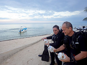
Showing Marco from CEA how the support system works.

Showing Marco how the support system is assembled.    (Photo courtesy Monika Wnuk)

But it only took one look at the surf breaking over the reef to know that wave motion was going to dominate the kinetics. Fine if you are studying wave energy, but not so great if you want to gauge the direction of flow.  How was I going to tease the overall signal out of my little devices while they were being tossed around like that?  In the end I decided to really stretch the time between
accelerometer readings, hoping that my “average reading” would span the shorter frequency wave cycles.  Each sample would consist of thirteen separate accelerometer readings, separated by the maximum watch dog timer delay of 8 seconds, and then I would throw away the extreme high and low values before calculating an arithmetic mean. I was in the process of running tests with these modifications when Trish returned to our dorm room with Gabriel Rivera (from CEA’s water quality program), who told me that the centers director had arranged for a boat and that they already had an installation site in mind which they wanted me to look at. Trish already had a full schedule of work at Rio Secreto, including a public presentation of her cave research (in Spanish), so once again I drafted Monika as our team photographer and we set out for the launch.

Installing the sensor

Installing the sensor on the old buoy anchor (Photo courtesy Monika Wnuk)

The boat headed straight for one of the main reef buoys, and I was a bit concerned that they intended to anchor my delicate little sensors to that heavily chained beast. But once in the water, Marco guided me to an much older cement barrel anchor that was still in place, though it had rusted beyond use as serious anchorage. This was fantastic! We zip-tied the pivot and support rods into place, and returned to the boat for the sensor itself.  A few minutes later we had the sensor in place, but the poor thing was bouncing back and forth like a ping-pong ball. I had to do something to damp down those wild displacements, so I removed about 80 grams of the eternal ballast mass, giving the flow sensor a much stronger vertical restoration force.

Hopefully secure enough from boats, waves and tourists.

Secure enough from boats, waves and, hopefully, tourists.

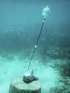
The unit was in the center of the water column (at about 3m) and despite the roil of the surf above it now seemed to be consistently leaning in the direction of the particles we could see floating by. Our first open water unit had been deployed!

Our boat rental about to expire, and I now knew that I had to alter the ballast on the two remaining units, so we returned to shore for showers and a late lunch. Gabriel and I re-calibrated the last two units in a tide pool, and I gave him the last of our anchors and support rods so they could install the last two sensors after CEA staff had a chance think about other suitable locations.

After that I drove up to Rio Secreto,  making just in time to catch the end of Trish’s presentation. Her talk ended with a gratifying burst enthusiasm from the R.S. staff as we handed the 2 bar pressure sensor over to the science liaison who had been our guide a few days before. She promised to put it into the cave near the drip sensors as soon as she had an opportunity.

So I would be returning home with only one of the 13 units I had brought down, and in total this trip would see 16 different sensors running in the wild.  Brilliant!  Now it’s time for me to start digging into all that data…

<— Click here to continue reading the story—>

Field Report 2014-09-01: Our first “deep” saline installation

I was keen to see if the Pearls were sensitive enough to track the slower deep water circulations and Trish has an ongoing collaboration with some UNAM researchers studying cave organisms in a system called Ox Bel Ha.  With the new build, I was confident that we could push the envelope a bit, so we planned a dive to a deploy the remaining two Cave Pearls in the deeper saline zone of that system. (around 20m)

Did I mention how much I dislike tábanos?

…thirteen…slap!…point…rrrrgh!…seven…

Once again our friend Jeff loaned me some of his dive equipment, and even better, both he and his partner Gosia, were able take a break from their busy instructor schedules to join us for the installation.  Jeff had often offered his services to researchers in the past, and I think my nerdy enthusiasm amused both of them.  As with previous installations, I calibrated the buoyancy of the sensors at the surface with a small hand-held postal scale. Deeper systems tend to have slower flows, so I adjusted the Pearls to only 10 grams negative buoyancy. This was pretty close to the wire for a system at full marine salinity, but with flows down in the 0-5 cm/s range I was hoping for the best sensitivity I could get. With our kit sorted we put in at a rather boggy zero-vis cenote whose large population of mosquitoes & tábanos which the pre-dive checks at the surface a trial, despite the fact that they had already feasted on me while I did the buoyancy calibrations.

I was sad that we had to leave my little waterproof point&shoot at the surface, because it was a beautifully decorated system, with intersecting passages at multiple levels. Three of us followed Trish’s lead out to a nice wide section where we waited patiently on the line while she inspected the cave with her hydro-geologist’s eye. She found a spot, with a roof profile suitable for our bungee anchors, and instructed me to connect three 50cm segments to pivot, putting the meter in the center of the passage, at 22m depth. With the supports connected I returned for the first flow meter, only to make the unwelcome discovery that both of the sensors were now positively buoyant. Arrrgh! I had cut it too close by calibrating to only -10 grams in the fresh water of the cenote! We transferred a couple of five gram ballast washers over from the second unit, but we still had a slow persistent rise to the ceiling. Trish provided a temporary solution by adding a metal dog clip to the support rods, and since we only had the one spare clip, we called the dive with our second flow meter still in the bag.

Despite the buoyancy problem, everyone was happy with the overall simplicity of the installation procedure, and Jeff graciously offered to re-calibrate and install the orphan meter the next time he was in the system (and he wanted his clip back 😉 )With our shortened trip schedule, we took him up on the offer, and after a celebratory cerveza in Tulum, we gratefully left him with all the pieces he would need for the second installation.

<— Click here to continue reading the story—>

Field Report 2014-08-26: Old Flow Sensor Inspection

The drip sensor deployments left me with an couple of hours free time that evening, which gave me a chance to take a closer look at the flow sensors we pulled the day before.

From the same batch?

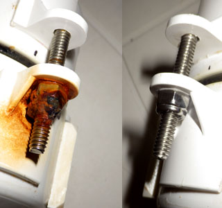
Different corrosion  although nuts & bolts were identical

The most obvious impact of the near marine exposure was the rust that had accumulated on the stainless steel bolts and ballast washers. (no spec on the bolts, but the lock nuts were 18-8) While they fasteners were all purchased at the same time, they showed dramatic variation in the amount of oxidization they sustained. I can only presume these are the result of the manufacturing process leaving scratches which acted as nucleation sites. Even the fasteners that suffered significant oxidization remained secure and they were relatively easy to remove once the surface rust had been brushed away.

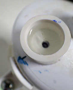
Still clear, and nothing growing on the surface.

E-30CL still  clear, with nothing growing..

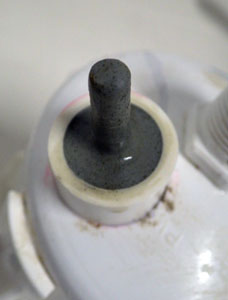
Some pitting on the JB weld surface.

Some pitting on the JB weld surface. I had some concern that the iron particles in the J-B weld might induce galvanic corrosion on the other metal parts.

Both epoxies proved to be far more robust than the manufacturers testing indicated, with the Loctite showing some surface fogging on two units, while remaining perfectly clear on the other one. The grey JB marine weld changed from a smooth surface to one with significant grit (~400 grit sandpaper?). I suspect the pitting is a result of the iron particles in their formulation rusting out of the the matrix, and I will try to get these puppies under a microscope later.  The rubber 0-rings were still in pretty good shape although they had a significant layer of bacterial slime on the exposed surfaces which I cleared off with a touch of isopropl alcohol. I suspect that any material with suflur in it is a banquet for critters the low energy cave environment, but the O-rings certainly look like they will survive for at least a year. (something for me to keep in mind with the bungee anchors though, as the older one’s are at 9 months submersion now)

Three of the four units pulled their 6 x AA power supplies into the 3.3 volt range (as read by the Atmel internal 1.1 vref trick) ; more power drain than my earlier tests had indicated for a 5 month run. But those bench-top tests were done too fast to include self discharge, without isolation diodes, and the real world batteries had been exposed to a relatively high humidity for the duration. (I have added 10 gram desiccant packs to the current crop.)

Perhaps the most interesting power consumption result was from the one unit that included a voltage regulator in the power supply module. I was unable to measure the cell voltage directly till a few days after the units were disconnected, but after the rebound period the AA’s supplying the NCP1402-3.3V Step-Up regulator were at 1.35v, while identical cells that had powered the unregulated Tinyduinos were at 1.4 v.  That’s a pretty small difference given that the nominal efficiency of the regulator is around 75%.

I will have to analyze the rest of the data later because the little net-book I have with me doesn’t have the gumption to chew on data sets of nearly 34000 records. So now we have the three older model Cave Pearls (and a pressure sensor!) cleaned up and in working condition… I think it’s time to put some thought into our next experiment!

Field Report 2014-08-26: The First Drip Sensor Deployments

Selecting test locations. (Photo courtesy of Monica Wnuk)

We were spoiled for choice of locations in a beautifully decorated system like this.  (Photo courtesy: Monika Wnuk)

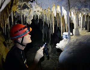
Yesterdays success with the flow meters meant we could now turn our attention to deploying the new drip sensors. Trish had ongoing work in the Rio Secreto Nature Reserve section of Pol Tunich cave, included an interesting student project monitoring calcite raft deposition. A maintenance visit to those experiments was already on the schedule, so it was an obvious choice to use that site for our first drip sensor deployment as well. Even better, Rio Secreto had several capable science liaison staff, some of whom were conducting experiments of their own nearby.

Units are tethered so flood conditions don't wash them away.

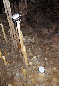
When you do something for the first time in the field, you tend to improvise allot, especially when you are trying to apply the Goldilocks principle to something as random as cave drips. But Trish seemed to know exactly what she was after, and with the help of our guide from Rio Secreto, we quickly started locating ‘gotas’ that were ‘just right’.  We knew from Kayleen’s video that the water level in the cave could be highly variable so we tethered the units located close to the water level to assure that flood conditions would not wash them away.


ComparisonTest

They are intentionally placed at an angle, so that water does not pool on the sensor surface and cause spurious readings.

We also wanted to set the sensors in areas with multiple drips in relatively close proximity.  Trish has always been fascinated by the question of why some drips readily form deposits while others quite nearby,  possibly with similar chemistry, are much less capable of creating decorations. With this in mind our guide led us to a wonderful “stalagmite garden”  which had many excellent drip sites for comparison.  We found that the soft, slightly concave rubber bottom on the drip sensor housing made it very easy to perch the sensors without harm to the stalagmites. Several units were set up in short order, and as we exited the cave we could see their little green indicator lights blinking away in the darkness behind us.  Even with the help of lithium AA batteries, there is a fair bit of uncertainty about how long these units will actually run, so I was quite happy to hear our guide Fernanda say that she would stop in to check on them when she had the chance. The sensors are designed to light a red led when the battery voltage falls too low, but I told her to remove and disconnect them before that if they showed any other unusual behavior. These units were assembled with an assortment of cheap clone boards, most of which use the MIC5205 voltage regulator, and I will be especially keen to see the performance of the one build with the Rocketsream Ultra, as it’s MCP1700 delivered some very low sleep currents during my bench top testing.  My hope is that we get at least four months of good data from all of them before the batteries expire.

<— Click here to continue reading the story—>

 Addendum 2014-12-12:

This first deployment was a great success, which you can read about here.

Field Report 2014-08-25: Retrieve & Deploy New Flow Sensors

We started the day with breakfast at Turtle Bay Cafe, and once I had enough caffeine in my bloodstream to engage more than two brain cells at the same time, I reviewed the data on the SD cards from the overnight test runs. They all looked good.  Over breakfast we met up with Monika Wnuk, a multimedia journalist and documentary photographer from Northwestern University, who wanted to interview Trish for a water & development story she was working on. Yesterday, when she heard about our abbreviated schedule, she volunteered to help with the sensor preparation, and to provide shore support for our deployment dive. I was glad for the assistance, as two scheduled days were now being merged into one single operation.

Pre-dive planning with Bill, Trish, Monica & Jeff.

Pre-dive planning with Monica, Bil, Trish & Jeff.

Our diving field work almost always begins with a visit to Speleotech in Tulum, to see our long time friend Bil Phillips. Bil taught me to cave dive many years ago, and I still have much to learn from that remarkable man, who is without doubt one of the most dedicated cave explorers in the world. We also had the good fortune of meeting another good friend, Jeff Clark, who loaned me some equipment I needed for the days dive. The dive community in Tulum has always been generous to visiting researchers because they understand, more than most people, what is at risk with the rapid development that is happening in the region.  We all share a passion for protecting the caves as both a vital water resource, and as areas of natural beauty & wonder.

Checking for rotation, damage, etc.

Inspecting the old units for rotation, damage, etc.

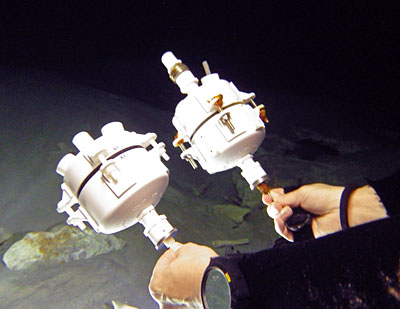
With the kit sorted, we headed out to our main deployment site where I began to adjust the buoyancy of the new sensor units. With the new internal copper ring of ballast mass (45g), and heavier
aluminum battery holders, it only took 2-3 external washers to bring each unit to my target of 15 grams negative. This is slightly heavier than the last deployment but I am expecting any reduction in the tilt angle to be more than compensated by the 14bit 1g resolution of the new BMA180 accelerometers.  With
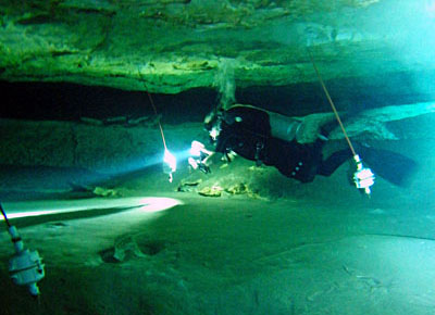
calibration out of the way,  Trish and I set off on the dive. High tide at the coast meant the system was experiencing very low flow, so we had a relaxed swim, with three new pendulums and a pressure sensor stowed neatly in the mesh bag by my side.

Old vs. New

New  vs. Old

Once at the site, the first task was to do a general inspection of the old units, noting anything unusual in my dive notebook.  After almost five months of submersion, there was plenty of rust on the stainless steel bolts and one of the units needed it’s anchor plate replaced.  Using the checklist I had prepared earlier, we swapped each unit in succession with it’s replacement.  In the calm conditions, percolation obscured our view a bit as our bubbles meandered around the ceiling of the cave, but it was still a very simple operation to exchange flow sensors.

Once the new units in place, we did a final inspection swim:

…checking that the new units were secure, with the X axis of the accelerometers oriented toward north.  While this is not strictly necessary with magnetometers inside the units,  I can use it as a rough confirmation of the compass bearings when I get the chance to do some proper data analysis later. I gathered the old sensors into the mesh bag and we made our way out of the cave.  I am not sure I can fully express the excitement that an inventor feels returning from a dive like this, but it’s very, very cool.

I think there is an ocean and a sunset in this picture. But at the time, we did not even notice it.

There is an ocean and a beautiful sunset in this picture. But at the time, I don’t think we even noticed it. (photo courtesy Monika Wnuk)

Back at the surface we had a chance to do a better visual inspection of the old units, which all appeared to be intact. I had some concern about the hull penetrations, as none of the epoxies were rated for long duration marine exposure. But the indicator LEDs were still piping on schedule, telling us that they were all still running.  Back at the dorms, we were equally thrilled to find complete data sets recorded on the SD cards.  (I will post more on the actual data after we have a chance to work on it.)

 <— Click here to continue reading the story—>

Field Report 2014-08-24: Assemble & Test all data logger units

Re-assembling the units

Putting the Pearls back together again.

Life intervened while we were still mid flight to Mexico, making it clear that this trip was going to be much shorter than expected. We would have only 5 days on the ground instead of the planned 12.
I started re-assembling the new drip sensors in the car as soon as we left the Cancun airport. With a 15 minute sampling schedule they would need a full 16 hours before data buffered in the eeprom would be written to the SD cards.  Later that day I put the flow sensors back together and loaded the final deployment scripts. With the flow sensors using a short five minute sample interval,  they only need 8 hours to complete a full cycle. While all the units had been tested at home, I always want to see at least one more successful run before a unit is installed into a cave.

One dead soldier before it even goes in the water

We had one dead soldier before it even went into  the water

The software for the unit with three accelerometers still needed some final tweaking, so I set to work on that (I had the epoxies clamped on that one till the last possible minute before packing) but it turned out that the ADXL345 would only read on the x & y axis.  As it was too late to fix the problem,  I just commented that sensor out of the code.  The resulting script will only give me data from the BMA180 and the BMA250 but that is still enough to bridge the data sets from our main installation site. Fortunately the three temperature pearl was running well, and I will be quite keen to see how those sensors differ in their behavior once the unit is in the actual cave environment.

Addendum 201409-10: Looks like I might have made a mistake with the ADXL345. Turns out that many of them are so badly calibrated from the factory that the Z axis is almost useless unless you change what’s in the offset registers. I live and learn.

Project Update: Gearing up for field work 2014-07-20

GluingSensorsThe last two weeks have been a complete blur of sanding, gluing & soldering, with simultaneous assembly of five next generation of flow meters, and six new dry cave drip sensors.  With the leftover beta unit I used for the long bookshelf power drain test, and the new 5 Bar pressure sensing unit, we will have 13 deploy-able Cave Pearls with us this trip.

Packed & Ready to go..

Packed & Ready to go..

Laying all this out, I realized that while our clothing for would easily fit into a single carry on, I could not remember the last time my wife and I traveled without two 49.99 pound suitcases of equipment. I make detailed component identification sheets for the TSA inspectors, who always return the favor by putting their own little pieces of paper in our luggage.  So far it has worked out OK.

Flow meter updates:

Since the last deployment, I have located better sensors for the flow meters and tweaked quite a number of things in the physical build. The new accelerometer is the BMA180, the only 14bit 1g accelerometer I could find on the market.  The venerable DS18B20 temperature sensor has been replaced by the Sparkfun TMP102, in my quest for completely interchangeable I2C sensors. Several new epoxies will also be tested in this build, including a very expensive Arctic Alumina thermally conductive epoxy to see if it will improve the temperature sensor response.

RosettaStone1

Does a logger with three temperature sensors know how warm it is?

I have built two special “Rosetta Stone” units for this deployment. One has the Ms5803-05, TMP102 & Ds18B20 temperature sensors, while the other has three accelerometers in it.  Data from these units will give me a head-to-head comparison of the sensor performance, and allow me to unite the data sets that we are generating with each successive build. The multi-accelerometer unit will sport the BMA180, BMA250 and the ADXL345. I think the 180 will come out on top, but there is always the chance that the increased sensitivity of that acclerometer will contribute more noise than accuracy to the overall performance.

The anchoring system now uses modular 50 cm long connecting rods, so we can hang the pendulums at different heights in the cave passage simply by adding or removing sections. (and they are much easier to transport in the luggage) Replacing the stainless steel rim bolts with nylon removed about 80 grams of ballast mass, so I have embedded a ring of copper inside the upper clam-shell. Hopefully this will improve the accuracy of  the data from the compass sensor.

Drip Sensor Progress:

Similar to one of the early flow meters, this would probably withstand submersion for quite a while.

Similar to one of the early flow meter designs, this would probably withstand complete submersion for quite some time…

Developed from a minimalist three component design, these are the first data loggers I have constructed where the mcu board possesses an always-on voltage regulator. Using only 3 AA batteries to power systems already sandbagged by the relatively high quiescent current of the MIC5205, really forced me to look for other ways to conserve power. Thanks to at tip from one 0f the advanced users at the Arduino Playground I discovered that the heartbeat LED pips are still quite visible when I use a whopping 10k limit resistor. This brings the 20mA LED currents well below 1mA, and if I sleep the processor while the LED is on, we save another 5mA for the pip duration. This little tweak will become part of my standard build from now on. Wherever possible I have replaced delay statements with brief MCU sleeps, and I am only reading Vcc once before the SD card writing process, since that is the only time the information becomes important. I originally conceived these units around the Sparkfun Pro Mini,  but early bench tests are indicating that the Rocket Scream Ultra could be the board of choice for future Cave Pearl data loggers.

<— Click here to continue reading the story—>