Field Report 2013-12-06: The moment of truth…

A couple of days into the UNAM research, there was break in the schedule, so we had the opportunity to go back and retrieve the units. When we arrived at the installation site, everything looked exactly as we had left it, with no apparent leaks or other damage to the housings.  But on closer inspection, we did observe that the two units were not exactly behaving the same way:

After catching a little more video, we spent a few minutes collecting the sensors. A short while later we finished the dive, and soon I was carefully cradling the loggers on my lap as we drove back to the CEA dorms. Once there I made sure that the units were absolutely dry before I opened them up to retrieve the SD cards.  I could see from the size of the files that both units ran smoothly, and had logged data. But what had they recorded?

Once the files were on the laptop, my wife, an Excel virtuoso, took over.  Within moments we were starting to see bumpy graphs displaying the three axes of the accelerometer.
A little more adjusting, a few labels, and we were looking at this:

3 days of raw data from the very first deployment.

Raw data from the first deployment: x,y&z axes, but with different orientations relative to flow direction.

“Is that good?” I asked. I could barely contain my excitement.

“Yes,” she replied with a big smile, ” for uncalibrated, first run data, this is pretty good.”

“Why two peaks per day?” I thought there might be a problem with the sensors.

“Actually.” she added, “That’s normal.  This area has semi-diurnal tides, and the velocity curves are often asymmetrical like that.”

“Yaayyyy!” I whooped, “We did it!” And I think I even started dancing.  Months of noodling around in the basement, and combing through forums, had just been transformed from “another one of Ed’s crazy projects…” into two real working prototypes!

It was well into the evening by this point, so we headed out for a late dinner, and a couple of celebratory ‘cervezas’.  We discussed where we might put them next, so that we could learn more about the quality of the data they were generating. I wondered about how we might calibrate them against some commercial units, and Trish said that even without ‘absolute’ velocity numbers, the information would still be useful to her research. But for me,  the real bottom line was the moment when she asked:

“How soon can you make me some more of these things?”

<—Click here to continue reading—>

Field Report 2013-12-03: The Full Monty

Trish ties off Unit 1

Trish ties unit one to the ceiling of the cave.

Although our field tests so far had uncovered buoyancy issues, both designs had remained water tight. So I was feeling brave enough to think about putting the electronics into the housings. And the UNAM crew was arriving in Tulum today, so I was about to loose my dive buddy to “real” research. We decided to go for it and install the little loggers, in a cave system, and leave them there for a few days taking readings every five minutes.

For this first deployment we chose a system that Trish had already calibrated for discharge many times over the years, allowing her to review any data that my little DIY units might produce within that context.  But given the buoyancy issues we had seen over the last few days, we decided to test everything in open water at the entrance.  And it’s a good thing we did as, once again, the o-ring design sank*… as you might imagine, I spent the next few minutes making some rather large bubbles.

…Once I regained my composure, we decided to make lemonade. If that unit was not going to float, then we would simply install it upside down, as a pendulum. The magnitude of the displacement would be almost the same, and all I had to do was change the sign on a few of the readings.  So we grabbed one of the anchors, and a bit braided line from the dive kit, and made our way into the cave.  I carried the anchor and poles, while Trish ran the dive reel leading us into the dark of the cave.  I have to admit I winced a few times as the mesh bag carrying her unit occasionally bashed into the nearby rocks, while her attention was focused on the line. I had visions of those Tinyduino stack connectors coming apart, “But hey” I told myself, “that’s what a this is all about.”  They would either survive the real world, or I would have to go looking for a different electronics platform.

We made our way to a location where we had installed one of the old RCM Aanderaa sensors, many years before. And while I found a place where the anchor didn’t sink elbow deep into the piles of organic mung, Trish tied off the pendulum unit. We did a few laps round the installation with the waterproof camera, to capture a little video, and then made our way back to the entrance. Our loggers were now out in the wild, collecting real flow data! The schedule was pretty busy for the next little while, so it was going to be a few days before we would be able to retrieve our units, to see if they worked. It will be interesting to see how the readings compare to each other.

I have my fingers crossed!

<—Click here to continue reading—>

*Some time later, we found that AA batteries vary considerably in their mass, and I had switched brands just before this deployment, throwing our buoyancy off again.

Field Report 2013-12-02: Another dunk test

In the evening of the open water tests, we reviewed video of the housings while talking (perhaps evangelizing is a better word…) to several friends at the Centro Ecológico Akumal where we were staying.

IMGP0273After sleeping on it, I realized that we had actually observed one other problem with the units the day before: Although the water flow was moving the housings, the videos showed that they did not quite lean at the same angle as the supporting pole. The second pivot point under the float was allowing the unit to try to right itself, reducing the tilt angle that the accelerometer would read. So the next day, while Trish was off diving with one of her students, I attached some foam floats to the support rods, which now had plenty of holes to vent any trapped bubbles, and I refashioned the float end of the support rods into a fixed ‘T’ junction.

IMGP0293After Trish returned, I put on my kit and we took the units in for their second real world test, again with a dummy payload.  With extra buoyancy on the lines, the o-ring design performed beautifully, and even with the really fast flow of this system, we were not seeing much wobble.  So I proceeded to setup the rubber bottom design, and this time I got to watch that unit slowly sink to the ground. Closer inspection revealed that the rubber end cap was slowly becoming convex. The water pressure at this deeper cave was much higher than it had been at the coastal site we used for the first test; so it was pressing the end cap inwards.

So day 2 of the field testing was nearly the mirror image of day 1, but it showed that I needed to re-enforce the soft rubber end cap somehow before that unit would behave predictably.  This also explained why we had heard the noise during the pressure test in the light maker’s dive shop:  the rubber must have been extremely concave during that test, so it sank to the bottom of the chamber with a “clunk”.

So another unsuccessful trial, but much was learned. So it goes…

<—Click here to continue reading—>

Field Report 2013-12-01: A pressure test for the rubber bottom housing.

The next day I needed to do some diving, both to test our kit, but also for me to just to get back into the “zen” that is cave diving.  This shakedown left us with one broken fin strap and one dead IMGP0219primary light. Which is pretty much on par for the beginning of fieldwork. We brought the dead light in for repair at the Dreams Tulum Dive Shop, where the owner (who makes dive lights and turns professional housings on his lathe) kindly offered to test my humble DIY housings in a pressure chamber he had fashioned from a decapitated scuba tank.  I was fairly confident about the o-ring design, but I still had lingering doubts about the one with the rubber end cap, so I jumped at the chance.  While the unit was still dry, I stuffed it full of toilet paper to act as an indicator for any water that might leak in. Then I put in the calibration weight, and he lowered it into the chamber. He pressurized it to about 100 feet and there was an a loud “clunk” sound at the start of the procedure; I feared the worst.

Perfectly dry after testing.

Perfectly dry after testing.

For the next ten minutes I paced the floor like an expectant father, much to everyone’s amusement. Then we depressurized, I dried off the housing, carefully loosened the pipe clamps to remove the end cap, and . . .

Whoo Hoo!  It survived with no leaks!  Not bad for $10 worth of plumbing!

But still I wondered what that noise was…

Addendum:  I did not find this out till after our trip was over, but the spec sheets list that caps maximum “working pressure” at a mere 4.3 psi. The pressure at 100 feet is almost 60 psi.  OOOPS! 

<—Click here to continue reading—>

Field Report 2013-11-30: The first “real world” housing test

I had some serious concerns about the wobble behavior observed during the early housing tests, and that vortex shedding might still kill the whole idea of measuring tilt as a proxy for water velocity. But without some real world observation there was no way to know if this was a lethal design flaw, or just an artifact of plain old surface turbulence. The support poles I had given the student to try out earlier were only 50cm long…

IMGP0171

The new housings get their first real world test.

So, even though we started our trip with a lovely bit of dry caving, I was very keen to get the new housings in the water before Trish started diving with her grad student and the diverse group of UNAM & Texas A&M researchers that would be arriving soon.

We piled all the bits into the rental car, and headed out to a local coastal outflow that was easy to access from the surface. I reasoned that if the units didn’t respond in the high flows at that site, there was no point in trying them out in the slower cave systems.  And, as this was to be the first test in anything deeper than a laundry tub, I decided it was safer to leave the electronics behind, and test them with simple calibration weights inside. We passed the usual gaggle of snorkelers on the way in, who stared curiously at all the plumbing we were carrying. A few continued to circle around above us as I set to work getting the anchors in place,  threading the poles, and attaching the housings.  At least I had proved that the thread plugs were easy to attach under water!

Right from the start the units appeared to be working: they were leaning in the direction of flow, and by 45 degrees (or more). I knew that the 2 G rating on our accelerometer meant we were using less than half the sensors range, but there wasn’t going to be any problem reading a signal that strong. And although we could see some of the wobble that the student had mentioned in the support poles, it was fairly mild except in the fastest flow areas. So the dreaded vortex shedding problem turned out to be far less serious than I had feared. I was happy!

IMGP0172
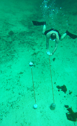
Trish and I spent the next little while swimming around the units, trying to see them from all angles, while the curious onlookers tried to figure out what the heck we were doing. But as we continued discussing the floats, working on where to move them next, a problem was slowly developing. Over the next 15-20 minutes, the o-ring housing, slowly, inexorably, sank to the bottom. The only logical conclusion I could think of was that the seals had failed, and that the Mark II, which I had so carefully assembled, was a failure.
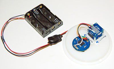
Later, after we had retrieved the units and dried them out at the surface, I cracked open our sinker, preparing myself for….Nothing! It was bone dry inside! How does something sink “slowly” without leaking? I put the cap back on and marched back over to the water, to dunk it in. And it floated, just as it had before, with just a small bump of pvc cresting the water. Hmmmm.

Then I grabbed the hollow support poles, tossed them in, and they floated too.  What was going on?  I moved the tubes around a bit, and spied a few small bubbles leaking out one end…Aaaha! They were not as buoyant as I thought they were. A bit more shaking to fill their internal volume with water, and I managed to get the poles to sink, very, very, slowly.

Then I jumped in, and pushed the housing down to the bottom; to observe it at depth. On the surface, it floated happily, but down around 15 feet, it rose much more slowly.  It dawned on me that I had been compressing the new o-rings for the first time! So the bubbles in the support poles were draining out, and, the internal volume of the housing was also changing with oring compression!

So today was not a failure at all!  I had simply shaved the buoyancy budget too close in my quest for more response to water flow. I could fix this…

<—Click here to continue reading—>

Project Update: Nov. 26, 2013

_IGP9138I’ve been doing run tests on the units over the last week or so taking samples every minute (simulating about 30 days in the field). Data logged well, but band-gap monitoring reported Vcc wobbling by more than half a volt once the supply fell below 3.8 volts. Not sure what to make the cutoff voltage though and I wonder if that monitoring code is a bit flaky?  Even so, the accelerometer ran smoothly with very little noise on the axis readings during the wobbling voltages. But I did see a bit of downward drift in the internal temperatures being reported by the RTC, and the accelerometer. Not sure what caused that.

The whole unit is showing about 60mv drop on the 3 AA no-name battery pack per 100 readings. That’s about a days worth of operation at 15 minutes sample intervals, which projects out to about 45 days of operation on a 6 pack before I hit 2.7 v (my current best guess at a ‘safe’ minimum voltage for SD card writes). Not great performance I admit, but good enough for some field testing anyway.

And a last minute batch of new boards arrived today from TinyCircuits, so I will have at least one full set of spare parts in the box if I need it…Sweet!

Q: I wonder what would happen if I let the little loggers run right down to the point where the internal brown out detector kicks in and shuts down the whole system? Would this hurt the SD card? No time for destructive tests now though, as I am on the plane to Mexico tomorrow morning.

Q: I wonder what other data I could be reading out of that bma250 accelerometer? If it’s got an internal bump detector, does that mean that it’s internally calculating theta on the fly? In which case I could read it out directly over I2C as well?

Q: I still have that old mma7361 lying around that I’d like to put in service, but I’m not sure how stable an analog device would be with an unregulated power supply?
A: I found a discussion of the issue over at avrfreaks. It looks like they the relative measurements stay the same, so if you are recording vcc, you can do the correction.


And talkin’ the talk…

Now that I think about it, that last bit of bloggy catharsis will probably be read to the end by maybe three people on the whole internet…if I include my mom. I’m sure the real coders felt a yawn coming on at the second line, and aside from the two other newbies out there at the “Just reading anything I can find.” stage, everyone else is probably thinking “Ok! Enough already… just gimme the code!”

So here you go. My first stable datalogger build* for a Tinyduino stack consisting of: a processor board, a BMA250 accelerometer sheild,  the microSD adapter, and a protoboard, jumpered to a chronodot RTC. The whole thing runs ‘unregulated’ off of 3 AA batteries, so I keep an eye on the bandgap voltage to (hopefully) stop data writes to the SD card when the battery voltage gets too low. But this part has not been tested yet, so don’t trust your life, or data for your thesis, to that kludge. Build yourself a real voltage divider!

*This scrapbook of code was cobbled together from the work of other people who actually know what they are doing, and my only real contribution was the hours I spent wading through forum threads collecting examples, before bolting this Frankenstein together.  So I take no credit for any of it, and provide no guarantees whatsoever that it wont brick your system the first time you run it. I also hope that anyone I’ve missed in the credits, forgives the accidental oversight, as some details get lost in the process of all that cutting and pasting.

// Date, Time and Alarm functions using a DS3231 chronodot RTC connected via I2C // and Wire library from https://github.com/MrAlvin/RTClib
// based largely on Jean-Claude Wippler from JeeLab’s https://github.com/jcw
// Clear alarm interupt code from http://forum.arduino.cc/index.php?topic=109062.0
// Get temp from http://forum.arduino.cc/index.php/topic,22301.0.html [which does not use the RTCLIB!]
// BMA250_I2C_Sketch.pde – from
// https://tiny-circuits.com/learn/using-the-accelerometer-tinyshield/
// which links to
// http://www.dsscircuits.com/accelerometer-bma250.html
// combined with internal voltage reading trick from:
// http://forum.arduino.cc/index.php/topic,15629.0.html
// floats to string conversion: http://dereenigne.org/arduino/arduino-float-to-string

//note: angle brackets which should be around library names are missing here due to formatting weirdness in WordPress

#include SD.h
#include Wire.h
#include SPI.h // not used here, but needed to prevent a RTClib compile error
#include avr/sleep.h
#include RTClib.h

#ifndef cbi //defs for stopping the ADC during sleep mode
#define cbi(sfr, bit) (_SFR_BYTE(sfr) &= ~_BV(bit))
#endif
#ifndef sbi
#define sbi(sfr, bit) (_SFR_BYTE(sfr) |= _BV(bit))
#endif

#define DS3231_I2C_ADDRESS 104 //for the RTC temp reading function

#define BMA250 0x18
#define BW 0x08 //7.81Hz bandwith
#define GSEL 0x03 // set range 0x03 – 2g, 0x05 – 4, 0x08 – 8g, 0x0C – 16g
//#define DELAY 10000 is this line an orphan?

RTC_DS3231 RTC;
byte Alarmhour = 1;
byte Alarmminute = 1;
byte dummyRegister;
int INTERRUPT_PIN = 2;
volatile int state = LOW;
volatile boolean clockInterrupt = false;
int SampleInterval = 1;
// power-down time in minutes before interupt triggers next sample

byte tMSB, tLSB; //for the RTC temp reading function
float temp3231;

const int chipSelect = 10; //sd card chip select

uint8_t dataArray[16];
//variables for accellerometer reading
int8_t BMAtemp;
float BMAtempfloat;
int x,y,z;
String BMAdata; //for passing back data from bma read function
char TimeStampbuffer[ ]= “0000/00/00,00:00:00, “;

int ledpin = 13; //led indicator pin

void setup () {

pinMode(INTERRUPT_PIN, INPUT);
digitalWrite(INTERRUPT_PIN, HIGH);//pull up the interrupt pin
pinMode(13, OUTPUT); // initialize the LED pin as an output.
digitalWrite(13, HIGH); // turn the LED on to warn against SD card removal

Serial.begin(9600);
Wire.begin();
RTC.begin();
//RTC.adjust(DateTime(__DATE__, __TIME__));
//the above line set the time with code compile time – you only run this line ONCE!
clearClockTrigger(); //stops RTC from holding the interrupt low if system reset
// time for next alarm
DateTime now = RTC.now();
Alarmhour = now.hour();
Alarmminute = now.minute()+ SampleInterval ;
if (Alarmminute > 59) { //error catch – if Alarmminute=60 the interrupt never triggers due to rollover
Alarmminute = 0; Alarmhour = Alarmhour+1; if (Alarmhour > 23) {Alarmhour =0;}
}

initializeBMA(); //initialize the accelerometer

//get the SD card ready
pinMode(chipSelect, OUTPUT); //make sure that the default chip select pin is set to output, even if you don’t use it
Serial.print(“Initializing SD card…”);
if (!SD.begin(chipSelect)) { // see if the card is present and can be initialized:
Serial.println(“Card failed, or not present”); // don’t do anything more:
return;
}
Serial.println(“card initialized.”);
File dataFile = SD.open(“datalog.txt”, FILE_WRITE); //PRINT THE DATA FILE HEADER
if (dataFile) { // if the file is available, write to it:
dataFile.println(“YYYY/MM/DD, HH:MM:SS, Vcc(mV), X = , Y = , Z = , BMATemp (C) , RTC temp (C)”);
dataFile.close();
}
else { //if the file isn’t open, pop up an error:
Serial.println(“Error opening datalog.txt file!”);
}
}

void loop () {

if (clockInterrupt) {
clearClockTrigger();
}

//read in our data
BMAdata = String(“”); //clear out the datastring
read3AxisAcceleration(); //loads up the dataString
DateTime now = RTC.now(); // Read the time and date from the RTC
sprintf(TimeStampbuffer, “%04d/%02d/%02d,%02d:%02d:%02d,”, now.year(), now.month(), now.day(), now.hour(), now.minute(), now.second());
Serial.println(“Timestamp Y/M/D, HH:MM:SS, Vcc = , X = , Y = , Z = , BMATemp (C) , RTC temp (C)”);
Serial.print(TimeStampbuffer); Serial.print(readVcc()); Serial.print(“,”);
Serial.print(BMAdata); Serial.print(“,”); Serial.println(get3231Temp());

//write data to the SD card
// note that only one file can be open at a time,so you have to close this one before opening another.
File dataFile = SD.open(“datalog.txt”, FILE_WRITE);

if (dataFile) { // if the file is available, write to it:
dataFile.print(TimeStampbuffer);dataFile.print(readVcc()); dataFile.print(“,”);
dataFile.print(BMAdata); dataFile.print(“,”); dataFile.println(get3231Temp());
dataFile.close();
}
else { //if the file isn’t open, pop up an error:
Serial.println(“Error opening datalog.txt file”);
}

// setNextAlarmTime();
Alarmhour = now.hour(); Alarmminute = now.minute()+SampleInterval;
if (Alarmminute > 59) { //error catch – if alarmminute=60 the interrupt never triggers due to rollover!
Alarmminute =0; Alarmhour = Alarmhour+1; if (Alarmhour > 23) {Alarmhour =0;}
}
RTC.setAlarm1Simple(Alarmhour, Alarmminute);
RTC.turnOnAlarm(1);

Serial.print(“Alarm Enabled at: “);
Serial.print(now.hour(), DEC); Serial.print(‘:’); Serial.println(now.minute(), DEC);
Serial.print(“Going to Sleep for “); Serial.print(SampleInterval);Serial.println(” minutes.”);
delay(100);
//a delay long enough to boot out the serial coms before sleeping.

sleepNow();

//Serial.println(“Alarm 1 has been Triggered!”);
}

void sleepNow() {
digitalWrite(13, LOW);
cbi(ADCSRA,ADEN); // Switch ADC OFF
set_sleep_mode(SLEEP_MODE_PWR_DOWN);
sleep_enable();
attachInterrupt(0,clockTrigger, LOW);
sleep_mode();
//HERE AFTER WAKING UP
sleep_disable();
detachInterrupt(0);
sbi(ADCSRA,ADEN); // Switch ADC converter ON
pinMode(13, OUTPUT); digitalWrite(13, HIGH);
// turn the LED on to warn against SD card removal
// But I have some conflict between the SD chip select line, and the led – so the darned thing never lit!
}

void clockTrigger() {
clockInterrupt = true; //do something quick, flip a flag, and handle in loop();
}

void clearClockTrigger()
{
Wire.beginTransmission(0x68); //Tell devices on the bus we are talking to the DS3231
Wire.write(0x0F); //Tell the device which address we want to read or write
Wire.endTransmission(); //Before you can write to and clear the alarm flag you have to read the flag first!
Wire.requestFrom(0x68,1); // Read one byte
dummyRegister=Wire.read(); // In this example we are not interest in actually using the bye
Wire.beginTransmission(0x68); //Tell devices on the bus we are talking to the DS3231
Wire.write(0x0F); //Tell the device which address we want to read or write
Wire.write(0b00000000); //Write the byte. The last 0 bit resets Alarm 1
Wire.endTransmission();
clockInterrupt=false; //Finally clear the flag we used to indicate the trigger occurred
}

// could also use RTC.getTemperature() from the library here as in:
//RTC.convertTemperature(); //convert current temperature into registers
//Serial.print(RTC.getTemperature()); //read registers and display the temperature

float get3231Temp()
{
//temp registers (11h-12h) get updated automatically every 64s
Wire.beginTransmission(DS3231_I2C_ADDRESS);
Wire.write(0x11);
Wire.endTransmission();
Wire.requestFrom(DS3231_I2C_ADDRESS, 2);

if(Wire.available()) {
tMSB = Wire.read(); //2’s complement int portion
tLSB = Wire.read(); //fraction portion

temp3231 = ((((short)tMSB << 8 | (short)tLSB) >> 6) / 4.0); // Allows for readings below freezing – Thanks to Coding Badly
//temp3231 = (temp3231 * 1.8 + 32.0); // Convert Celcius to Fahrenheit
return temp3231;

}
else {
temp3231 = 255.0; //Use a value of 255 to error flag that we did not get temp data from the ds3231
}

return temp3231;
}

byte read3AxisAcceleration()
{
Wire.beginTransmission(BMA250);
Wire.write(0x02);
Wire.endTransmission();
Wire.requestFrom(BMA250,7);
for(int i = 0; i < 7;i++)
{
dataArray[i] = Wire.read();
}
if(!bitRead(dataArray[0],0)){return(0);}

BMAtemp = dataArray[6];
x = dataArray[1] << 8; x |= dataArray[0]; x >>= 6;
y = dataArray[3] << 8; y |= dataArray[2]; y >>= 6;
z = dataArray[5] << 8; z |= dataArray[4]; z >>= 6;

BMAdata += String(x);
BMAdata += “,”;
BMAdata += String(y);
BMAdata += “,”;
BMAdata += String(z);
BMAdata += “,”;
BMAtempfloat = (BMAtemp*0.5)+24.0;
// add digits of BMAtempfloat value to datastring
BMAdata += ((int)BMAtempfloat);
BMAdata += “.”;
int temp = (BMAtempfloat – (int)BMAtempfloat) * 100;
BMAdata += (abs(temp));
//the following 2 lines also to convert float to string
//dtostrf(floatVariable2convert, minStringWidthIncDecimalPoint, numVarsAfterDecimal, charBuffer);
//for example: dtostrf(BMAtempfloat, 5, 2, dtostrfbuffer); dataString += dtostrfbuffer;
}

byte initializeBMA()
{
Wire.beginTransmission(BMA250);
Wire.write(0x0F); //set g
Wire.write(GSEL);
Wire.endTransmission();
Wire.beginTransmission(BMA250);
Wire.write(0x10); //set bandwith
Wire.write(BW);
Wire.endTransmission();
return(0);
}

long readVcc() { //trick to read the Vin using internal 1.1 v as a refrence
long result;
// Read 1.1V reference against AVcc
ADMUX = _BV(REFS0) | _BV(MUX3) | _BV(MUX2) | _BV(MUX1);
delay(2); // Wait for Vref to settle
ADCSRA |= _BV(ADSC); // Convert
while (bit_is_set(ADCSRA,ADSC));
result = ADCL;
result |= ADCH<<8;
result = 1126400L / result; // Back-calculate AVcc in mV
return result;
}

Walkin’ the walk…

I still have a long road ahead of me when it comes programming. But I figure that I since I started pretty near zero at the beginning of this project, I could share some thoughts on the process; before I forget what it was like. There were real benchmarks along the way, which made me feel pretty good when I achieved them, even if the goal posts seemed to move every single time.

Stage 1: Ummm, Is this thing on?

Initially, I was just reading the data from the sensors and sending that to the serial monitor to see what kind of numbers were being produced.  With the original Uno, and analog sensors like the MMA7260 this was just a few analogRead() statements. With a few simple lines of code, you know if you connected the wires properly. Still, it was cool to (carefully) move my little contraption around, see the numbers changing, and start thinking about how to calibrate the sensor, and whether I should  change AREF to get more juice out of the ADC. Also, to wonder if I should massage that data to get rid of all the jitter I was seeing in those numbers.

Stage 2: Going to the library.

Then I tackled writing the to the SD cards, copying code directly from the Adafruit datalogger shield tutorials. This introduced me to the concept of libraries: mysterious extra bits of code that I had to go find, and then #include with the program, to get the Arduino sketch to work. This was true for the SD cards, the RTC, and basically anything else that sent information to the microprocessor, rather than just putting a voltage on a pin.  These libraries are like the “killer apps” of the Arduino world. Without them, the best chip in the world remains unusable, hiding up in the rarefied atmosphere of embedded system engineers.  But as soon as one of those boffins decides to “release the library” he came up with for chip “IC-123”, then suddenly the forums light up, and all the lesser mortals start using that device in a big way.  Being one of those humbler people myself, my first step when wondering whether I can use a new widget, is to see if I can find libraries for it on github. And even though part suppliers like Adafruit, Sparkfun et. al. have turned this phenomenon into a thriving business model, the actual chip makers themselves almost never make the special sauce; leaving you to chew on the dry, salty, datasheets.

Stage 3: Can you I2C me?

Pullup resistors added to the chronodot RTC

Getting different two wire interface chips to share the same data “party line”, has benchmark status for me, because it was the first time software issues really forced me to go back and learn about the electronics seriously enough to raise my game. I spent days trying to figure out what pullup resistors were really doing, and whether the different boards I was cobbling together had put just the right amount on the lines. This was an important issue to resolve before moving on to the next stage of the game, but it also changed my understanding from “It either works or it doesn’t”, to the realization that there are many shades of grey in the way circuits are designed. Generally speaking, you get what you pay for.

Stage 4: Does this thing run on batteries?

Once all the chips were on speaking terms, and the data was being recorded on the SD card, it was time to cut the umbilical.  From a benchmark point of view, this is were all the software power management strategies come into play: the sleep codes really had to work, and the SQW alarm pulse had to wake the whole thing up again.  I also had to think about what would happen to all the circuits as the voltage started dropping. I had to learn about things like voltage regulators & level shifters, trying to find the weakest link in the chain, and then dug further into the forums to find out how far outside the specs you could actually go before you got into trouble.  In my project for example, I had prevent memory card writing if the voltage got too low or I would toast the memory cards, and loose all the data.

Stage 5: To infinity and beyond…

So this where I am now, and I am sure that there are many more “stages” ahead of me. The units are working for a reasonable length of time on batteries, but I still need to multiply that by a factor of two or three, to reach my year+ run time target. Preserving every last micro amp raises issues like data buffering to reduce the power hungry SD writes. This takes me even further into programming issues like variable optimization, because the code I cobbled together is now so large, that memory management is has become crucial. Or, if i work on my chops, I might be able to eliminate the SD cards entirely, and use eeproms for storage. Of course, each time I add a new chip or sensor into the mix, it sends me right back to stage 1 again.

The real take home message, for the people thinking about their first Arduino project is this: At each step of the way, getting a piece of  hardware to work required me to learn more programming, and each software problem I faced, forced me to learn more about the devices I was trying to connect. It’s sort of like climbing a ladder, by lifting one leg, and then the other. And as I passed each stage, the previous code folded into one small corner of the next version, adding layers of complexity like an onion. But I had no idea this was what the process would actually be like when I started out, because almost every thing I read at the time seemed to be written by technical geniuses that don’t have time for this kind of retrospective stuff.


A note on using the TinyDuino platform

_IGP9121I thought it might be good to put a few words in here on working with the Tinyduino system, because, although I really love the small footprint, and power optimization, you could say they were a “trial by fire” for someone with basic soldering skills.  Initially, I took one of their protoboards and added three rows of jumper pins to connect my RTC. This appeared to go ok so I painstakingly did this to all the proto-boards I had on hand.

But while it all seemed to go pretty well at first, I just could not get the darned RTC to work reliably.  I labored long under the chrondotassumption that I was making mistakes in the code (which hey, I probably was), or I had not pulled up the I2C bus properly, or there was something else I just had not learned yet. I eventually discovered that the tiny protoboard was slowly bending under the force of the jumper wires themselves, loosing contact with the stack, or shorting out on the layer below ( I did not have spacers in place to prevent this). And even when I fixed that, I still had weird intermittent faults occurring. Nothing is more frustrating than something that works fine most of the time, but then randomly cuts out on you.

_IGP9129In the end it turned out to be bridging between those really small contacts. I must have done it when I was soldering the pins on, but even after really close inspection, I could not see the bridge anywhere.  I ordered more boards, and started soldering thinner wires directly on, but then the wires themselves started breaking, because they were so fragile. I eventually figured out how to add some extra “support solder” by folding the wires over into a bit of ‘J’ hook, but even then they still couldn’t take much jostling around.  Now, I know there’s plenty of people out there just waiting to post a comment like: “If you are not already working with surface mount, just go home rookie”.

But I made this project blog in the hope that it might help other folks get rolling, so if, unlike me, you still have all your hair: do yourself a favor and buy a really good temperature controlled soldering iron, with ultra fine points in ‘mint’ condition. And I would recommend a fair bit of soldering practice, with a solder wick, before you jump in on those 0.1 inch Tinyduino proto-boards. Even then, buy extras, because you are probably going to go through them much faster than you think. I know I did.

Addendum 2014-02-10
And you don’t need to replicate my errors here any more because Tiny-Circuits has released an extended protoboard that you can buy naked for $5, or with terminal blocks!  These let you place the extension board in the middle of the tinyduino stack &  with all that extra space, I have soldered of riser pins on dozens of those new “double-wide” proto boards without any problems.  Also I now use soft multi-strand test lead wire with silicone insulation (instead of stiff PVC), which dramatically reduces strain on the solder joints.

A simpler housing design emerges.

I was happy with my Mark II design, but I realized that it was going to take half a day to make each one.  The latch clamps pushed the material cost to about $60, and the labor involved meant they were still going to be expensive in the kind of numbers Trish wanted for her network of cave sensors.  So I applied some thought to simplifying the design still further.

IMGP0029I had used some Fernco Quick-caps to convert the earlier botched housing bodies into anchors. It only took about fifteen minutes to create a one-piece housing, based on those, and I did not have to sand down any o-ring seats. Dayam! But my excitement was tempered when I put them in water, as the rubber end caps were so heavy that they rolled the units over, even with batteries in the PVC cap.  So I needed to come up with a way to attach these guys to the floor anchor, that maintained a rubber side down orientation. But I could not get anything to bond the flexing, bumpy outer surface of that rubber (which turned out to be “elastomeric pvc”)  In the end I threaded a fewIMGP0038 cable ties through pvc plugs, and suspending them under the pipe clamp. This worked but it only heightened my concern about the nature of the seal on these puppies. You see traditional O-ring designs actually work better on deep dives, because the added water pressure compresses the o-rings more tightly. This new design was super simple to build but it was also critically dependent on not one, but two pipe clamps made of metal, as I had to balance the mass of the clamp screw. Even with marine grade stainless, I had my doubts about the longevity of that seal. Nonetheless, I pressed on, and thought about a scaffold for the batteries and sensor package. A bit of IMGP0033ply, some hard foam insulation, and a touch of gorilla glue (an adhesive on my top five list of bodging materials) produced a battery compartment and electronics platform under 25 grams.  I added a ballast mass post with an old Ikea door pull, and put one of my new Tinyduino stacks into place. The hold down screws they came with were not long enough to penetrate that wood, so I had to fashion a U bend out of brass wire to affix the electronics.
Flow Sensor Housing by Edward Mallon

So now I had two different sensor housing designs. The more robust, o-ring design was expensive and took ages to make, while the simpler quick-cap housing, at about $10 material cost, it was definitely “Cheap as chips”, but it’s integrity relied on a couple of metal pipe clamps. I would not know if we had a winner until the next field work trip in late November. But even if this second design didn’t handle the water pressure at depth, I knew it was going to be handy for other cave research, because it was still a decent enough waterproof enclosure for less demanding environments.

<—Click here to continue reading—>