
Build Instructions Part 2: Connecting core components on a logger platform
Note: In Part 1 of this assembly guide we covered the preparation of the three main components being assembled here. If you have not seen that page yet you should probably start there.
 1. On a 4” PVC knockout cap, arrange your battery holders as close to the edge as possible to maximize room for other parts, without letting them hang off the edge. Mount them in place with double sided tape.
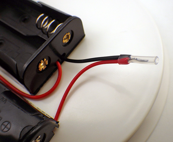
2. Join the black and red wires so that the three AA batteries are connected in series. Fold the solder join and the remaining red wire into the gap between the battery holders. Mark and drill 1/8” pair of holes to tied down the wires from the battery pack. Secure the wires to the cap with a zip tie through the holes.

 3. Place the RTC alongside the batteries with one corner near, BUT NOT EXTENDING OVER the edge of the cap. Mark two places for the M2 nylon standoffs and drill 2mm holes through the knockout cap. Thread the standoffs through the holes and attach them to the platform with a plastic nut on the underside of the cap.

4. Place the RTC board on the standoffs and fasten it into place with the battery side down. Then carefully drill two 1/8” or larger holes near the cascade port of the RTC board and fasten the I2C bus connector cable to the platform. Leave some play in the wires to that they are not under tension when the zip tie is tightened
5. With the RTC mounted on the nylon risers, add a thin layer of solder to each of the connector pins on the end of the RTC board.
 6. The next step is to use double sided tape to adhere both the Arduino, and the SD card adapter to the platform. The SD card must not hang off the end of the platform (so it’s a good idea to do this step with the card inside the holder to see the spacing) and the Arduino must not extend off of the platform. Do not push directly on the metal part of the SD card holder or you could damage it.

7. Once the components are in place it is time to start soldering the SPI bus wires to the bent riser pins on the Arduino. The trick is to hold the wire in place with tweezers, and trim each wire to length while still leaving a bit of play in the wires. Don’t cut them too short or you will not be able to solder the ends in place on the Arduino.
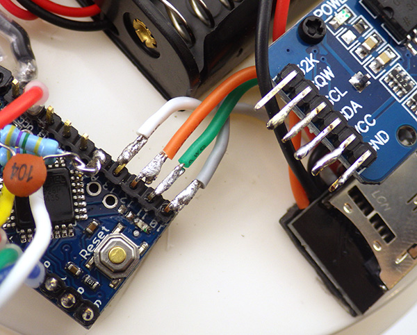 With the colors we used on the SD card adapter earlier:
- Grey wire is the spi CSelect line connect this to pin D10
- Green wire is the spi MOSI line connect this to pin D11
- Orange is the spi MISO line connect this to pin D12
- White wire is the spi SCLock line connect this to pin D13
If you used different colors on the SD adapter board you will have to figure out which of your colors correspond to each SPI line and connect accordingly. (check the wiring diagram) These can be left without heat shrink as they are tucked under other wires when the platform is completed, so an accidental touchdown is unlikely. Clean the joins with a Q-tip after soldering if there is a great deal of flux residue.
 8. Now pinch one of the GND wires from the Arduino and the ground wire from SD Card adapter together and hold them in place over the ground line for the RTC breakout. Cut them both to length, strip the ends and twist & solder both of the two ground wires together.
 9. Do the same with the red VCC wires so that the 3.3v regulated power line from the Arduino joins the VCC line and the power wire from the SD card adapter.
Using a pair of pliers to hold the wires in place so you don’t burn your fingers, solder the combined VCC and GND wires to the matching connector pins on the RTC
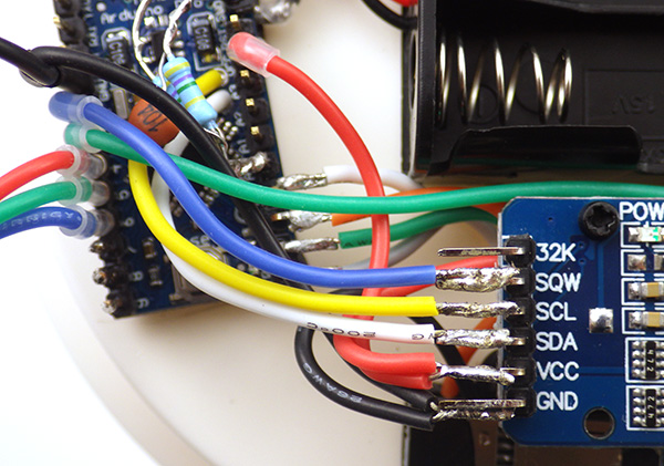 10. Now bring the (white) A4 wire from the Arduino to the pin SDA pin on the RTC board. Trim this wire to length, strip, twist and tin the end of the wire. Then solder this wire to the SDA pin.
Repeat this process for the (yellow) SCL wire from A5, and connect the (blue) interrupt pin 2 wire to the RTC pin labeled SQW.
 11. After drilling a couple of holes in the platform, secure the three Red Green and Blue wires from pins 4, 5, & 6 together with the second black ground line from the Arduino. Also secure the battery power leads from side of the Arduino board with drilled holes and cable ties.
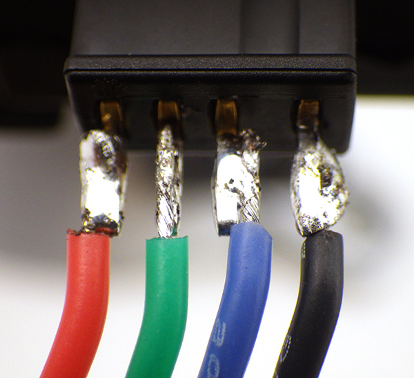 12. Trim the LED wires to the same length. Strip and Tin the ends, then solder those the ends to the female side of a black WSD1241 Micro 4B plug in the order R,G,B-GND (with ground on the dimpled side of the connector).
As with the I2C connector pre load the pins on the connector with solder & thread the heat shrink over the wires first. Be sure you are using the female connectors on the Arduino side of these interconnects because they are the ones delivering power.
 13. The final step on the main platform is adding connectors to the battery holders and the Arduino input leads. Start by trimming the battery leads to a position about ½ way across the battery holders. These wires are can be fairly thin so reinforce their insulation with a few layers of heat shrink before trying to solder them to the pre-tinned battery connector posts. Before soldering these beefy connectors make sure the male side has been inserted so that the nylon does not soften and let the metal contacts inside shift around when you are applying heat. They really get hot during this process!
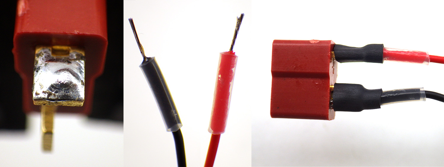
14.  Now measure the wires from the Arduino against the connector that is already in place on the battery holder side. Use the same procedure of reinforcing the wires with 1/16” poly shrink wrap before connecting to the main power tabs and adding a final layer of 1/8” 3:1 heat shrink tubing over the connections. The Arduino should be on the male side of the main power connector.
 Before trying to run your data logger from that battery module, it’s a good idea to test the battery holder connections with some AA batteries. If your 3x AA battery module is above the promini voltage regulator 3.5v minimum, you can connect the logger to see if it is still running the blink sketch. (provided you did not remove the p13 led)
At this stage the main logging platform is ready although the RTC clock has not been set yet.
Note: In Part 1 of this assembly guide we covered the preparation of the three main components that were used here. This post covered connecting the core components of the main logger platform, and in Part 3 we will cover mounting sensors onto the housing assembly to finish the data logger build. Part 4 covers techniques for optimizing your loggers power consumption, but some of them are more advanced so its probably a good idea to build a couple of the basic three component loggers before tackling everything there.
