There is an old saying that goes: “Yesterdays solutions are today’s problems” and I think that now describes this project. You see the first year of development was focused on pretty straightforward hardware issues, and solving each one produced significant gains in performance. Now that I am consistently seeing sleep currents in the 0.1-0.2 mA range (with an SD card (~80uA) & live Adxl345 (~50uA) along for the ride), I am hunting for more elegant ways to extend the operating time while maintaining the simple three component core of the original design. With a 3xAA power pack now providing almost a year of operation for some sensor configurations, I also have the task of developing a method for testing the loggers that can discriminate between subtle code changes with relatively short runs. But artificially reducing the sleep interval between samples distorts the result enough that it’s hard to make good projections. I am slowly coming to realize that testing & calibration are the real heavy lifting when you build any new device.
The new A544 cells arrived at > 7 volts which was too high for the regulator on the Ultra. So I took them down to 5.6 volts with a Zenner that stops the discharge before it goes too far. The rare earth magnet soldered to the leads gets zapped by the heat from the iron, so you need a second little magnet to hold each battery connection securely.
Each new trick I try, like finding another place where I can put the cpu to sleep, adds complexity to code that has “once per day events” and “once per week” events, and soon there will be “only if the delta between two readings is greater than x” events. Most of these are so short that a multimeter can’t catch them but even when a friend donated an old Tektronics to help me try to get a handle on the duty cycle, I faced the challenge of displaying currents ranging from less than 0.1mA to 80mA SD writes with variable duration. To make things more interesting, some of the cheap sensor boards I have been noodling around with have components of unknown origin & dubious quality, which introduce yet another set of variables.
Even with my mediocre scope-skills the forums had convinced me that the SD card was the elephant in the room. So I tried to avoid SD use by adding an external 32k eeprom which let me buffer five or more days worth of data before having to fire up the external storage. Problem solved…or so I thought. I was quite surprised by data from the last deployment that showed using this approach to reduce SD writes by a factor of five only delivered a 5-10% improvement overall. I had overlooked the fact that the AT24C256 eeprom pulls 3mA for five milliseconds per pagewrite. This was nearly as much current as the Rocket Ultra I was using, not to mention a significant extension of the cpu uptime for multi sensor units that were buffering up to four eeprom pages per record. All of that activity adds up.
So I took another look at buffering data in SRAM, which I flirted with at the beginning of the project. But my script was now much larger than those early versions, leaving barely 500 bytes free. I know the real coders out there probably laugh at my use of Pstring & Ascii but that lets me add a new sensor by changing a couple of print statements, and adaptability has always been of my primary design goals. To maintain that simplicity I went searching for an Arduino with more headroom and the Moteino Mega over at LowPower Labs seemed to fit the bill with it’s 1284P offering an extravagant 16K of sram (compared to just 2K on the 328p). It also used a low drop out MCP1700 series regulator like the Ultras, and there was support for RFM transceivers. With the Mega’s larger footprint, I decided to try them first on the larger dry cave platforms:
Rocket Ultra (left) VS Moteino Mega (right) based data loggers with pin powered RTCs and 2×4.7MΩ voltage dividers monitoring both the power supply voltage and the rtc backup battery. I break out LED, I2C and one-wire with Deans micro connectors, and you can see a 4.7K one-wire pull-up above the main divider on the Mega. A 32K eeprom is tucked away under the rtc breakout, which I flipped over on the Moteino build to make it easier to change the CR2032.
For a standardized test, I set both loggers buffering 96 records (= one day @ 15min intervals) in drip sensor configuration. I added the I2C eeprom to the Moteino logger to make the builds as similar as possible, but it does not get used. Instead I store the raw sensor data in integer arrays. So there is no Pstring/ascii use on the Mega logger until I write the data to the SD cards. With matched acclerometers & cards, both loggers sleep at 0.18 mA so the the only difference between them should be the data handling. One thing I did not catch from the LowPowerLab specifications was that the 16mhz Mega draws ~12 mA (while awake) in this configuration as compared to the Ultra builds which perk along at just over 4mA. I figured that with SRAM storage the mcu up time would be so much shorter that it would not matter.
With a parallel bank of super caps to buffer SD events, you can drive the loggers with small batteries that have high series resistance. Rare earth magnets let you connect without a holder and you can build multi-layer magnet/button cell stacks to create low power options at different voltages. Those are 5v 1farad supercaps so I don’t bother to balance them as they should be able to handle any leakage asymmetry when the battery input is only 5.6 volts. The graphs below had no low volt blips at all, so this series/parallel arrangement of 4 of them was probably more capacity than I needed.
I still had not sorted out the oscilloscope issues but I realized that I could flip the problem around: instead of struggling to display the effect of every little tweak to the duty cycle why not provide a fixed amount of power and just see how long the unit runs. It’s a data logger, so I already have a time stamp and a battery voltage reading with every record. A couple of people suggested capacitors, but even a 1F supercap only gives you about 0.27 mAh per volt, translating into a few hours of operation for my loggers. I needed longer runs than that because the Moteino was going to loose the data in it’s sram buffer when the unit browned out (I can always dig into eeproms later for the last few records on the Ultra). A bank big enough for multi day runs was going to be expensive, and is probably a hazard for my little bots.
Fortunately there are a host of small form factor batteries out there for things like fire alarms, medical devices, etc. Energiser’s A544 seemed to fit the bill at 6 volts & 150 mAh: promising to power the Pearls in “sleep current” mode for about 40 days. Even better, they were alkaline cells, so their discharge curve would be more like the AA’s used in real world deployments. There was some risk that these little cells would drop to the low voltage cutoff when the SD write current spikes occurred, so I added a few super caps to buffer those loads. I then set the units up on a book shelf where they would not be triggered and waited for my “baseline” load result.
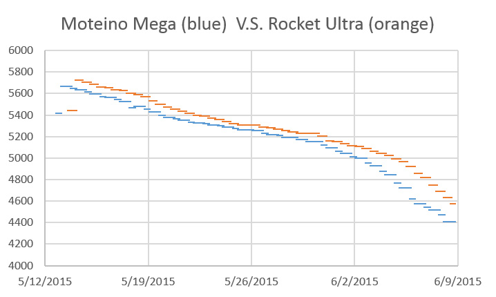
This is the voltage record from the two different logger platforms, when they were powered by a single 150mAh A544:
(I stopped the test after a month, because I couldn’t take these suspense any longer. There were few sensor interrupts during the test, so this was a baseline power use comparison)
I was sure the SRAM buffering Moteino logger would come out far ahead of the Rocket build that was sandbagged by all that I2C eeprom traffic. But if you correct for the slightly higher starting voltage those two curves are so close to each other they might well have come from the same machine. So there is no longevity boost from SRAM buffering if I use an mcu that draws 3x as much current, but at least I now have a good way to test the loggers without waiting too long for results. This result also agrees with some of my earliest drip sensor results which hinted that the sampling/buffering events were consuming 2/3 of the power budget.
For the next round of tests I will put them on the calibration rigs to see how the A544’s handle the interrupts being triggered all the time. Presumably the Moteinos will draw more power there so I will need to normalize the results to match drip counts. To go beyond the conservative one day buffering I will need some way to capture data from the SRAM buffer before the units power down, so perhaps I will end up using the eeprom on those Moteino Mega builds after all. We will use a few Mega based drip sensors set for very long buffering (8-10 days?) on the next real world deployment. I also have a feeling that the DS18B20 temperature strings would benefit more from SRAM buffering than these simple drip sensors, as they poll up to 40 sensors per record. That’s a lot more data to shuffle around.
Addendum 2015-07-05
Hackaday just posted about [Majek] putting “live” data into Arduino’s flash ram (which is normally not accessible after startup) via a Optiboot hack. This opens up another possible data buffering strategy, though I am not sure if it could handle the duty cycle of a long deployment. Or it might let you do calculations with the 328p that would otherwise run out of space. So this is an interesting development that involves no extra hardware, which is usually good news for the power budget. I had already been wondering if calibration data could be stored in flash with Progmem, but that solution only works for data that is not changing all the time.
Addendum 2016-01-06
We finally have some data from the first field deployment of Moteino based loggers which store sensor readings in ram (array variables), rather than buffering all the data as ascii characters in an external eeprom like my 328p based loggers do.
Here is the power curve from a Moteino:
Battery (mV): 3xAA supply, 0.18 mA sleep current, 5 days of data in ram
And here is a directly comparable build using a rocket scream ultra with a slightly higher drip count (ie: number of processor waking events) over the duration of the deployment.
Battery (mV): 3xAA supply, 0.18 mA sleep, 5 days of data buffered to AT24C256 eeprom
So once again, these performance curves are so close that it makes no odds. But on the bright side, this confirms that accelerated testing with 150mAh A544 batteries does give me results that translate into real world. So this is still pretty good news even if the 1284’s did not deliver the magic performance bullet I was hoping for.
Addendum 2016-02-15
If I wanted something a bit beefier than the 150 mAh in the A544’s, I could hack my way into a 9v battery, and use half of the set of 500 mAh AAAA batteries you find inside. That would give me about 1/4 the power of the AA batteries I typically use on deployment.
I’m quite tickled about being able to replicate a task that you normally would need an oscilloscope to see. Of course my chances of actually catching one of those big unpredictable SD card latencies (from something like age related wear-leveling) is still pretty low, so I will continue to use this A544 method for solid longevity predictions.
Typical “dry” cave logger platform with a Groove I2C hub to interconnect the individual sensors.
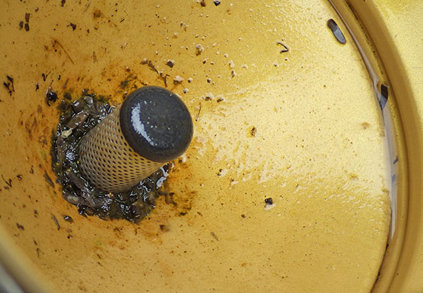
Reliable climate records can be hard to find for some areas, especially with the significant local variability you see in tropical locations. But it is important for understanding the hydrology of the caves so as I rebuilt the Pressure and R.H. loggers following the ECL05 epoxy failures, (I’m trying out some urethane this time round…) I thought a bit more about putting together a logging weather station. The temperature record from the “naked” drip counter we installed during the last deployment hit almost 60°C, which fried the SD card controller. This made it clear that any sensors on left on the surface need decent protection from the sun. A full Stevenson Screen is impractical to transport, and the smaller pre-made radiation shields seem unreasonably expensive for what they are (~$100 ea). Since I still don’t have a 3D printerto play with, I cobbled one together from dollar store serving plates and nylon standoffs which thread directly into each other; making it easy to add as many layers to the shield as you need. The trick is finding dishes made from flexible plastic like polyethylene that is easy to drill; polystyrene tends to be brittle and cracks when you try to make the large central hole. Even with a $6 can of spray paint thrown in, these shields only cost about $10 each, but I will try to find plates that are white to begin with for the next builds:
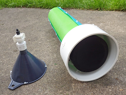
The cave drip sensors fit nicely into a 4-6 inch coupling adapter. The funnel uses a pex adapter so that I can change/replace the drip tips as I look for the best size to use. (currently 5.0mm heatshrink)
With temperature, pressure and relative humidity in hand the next task was to convert my cave drip counters into recording rain gauges. Earlier sensor calibrations had shown me that nozzle diameter was the key to consistent drip volumes, and I modified a funnel with some heat shrink tubing to yield a smaller 5mm tip. A large sewer pipe adapter provides a heavy stable base, offering the necessary sun protection and allowing me to add some inclination so the sensor sheds water from the impact surface.
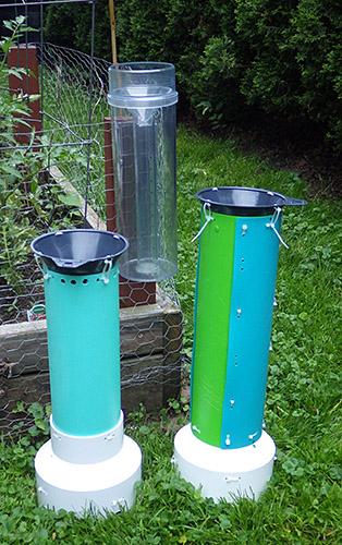
One unit has a riser tube made from Ikea cutting mats so that it will “flat pack” nicely into the suitcase. I will extend the tube to raise the catchment funnel if I can source parts locally.
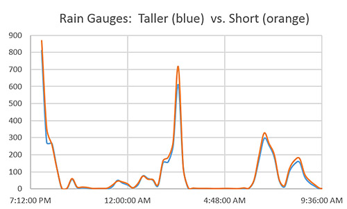
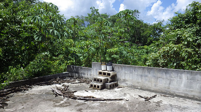
A riser tube then holds the catchment funnel sufficiently far away that the drops gain some momentum and these funnels do a good job of converting fine misty rains into drops big enough to trigger the sensors. As usual, everything is held together with cable ties so that it can be disassembled for transport. I picked up an old school Stratus rain gauge to calibrate the loggers and set everything up in the back yard just in time to catch a few summer thunder storms. Ideally these gauges would be up off the ground, out in an open field, but my yard has few areas that are not directly covered by trees. I also noticed that high winds can sometimes shake the units enough to create false positives, so I now anchor the bases to cement blocks. Even with these sub-optimal factors, these loggers report within 10% of each other. Not USGSquality yet, but I am happy with them as prototypes. I will add a larger 8′ funnel later, to bring the loggers in line with NOAA standard rain gauges.
A subset of data from one of the calibration runs with the count binned at 15 minutes. Thirty one millimeters of rain fell during this test and the nozzles are producing between 12-13 drops per mL of water. Differences between the funnel tips become more pronounced at the higher rates.
Wind is the next piece of the puzzle, and I still have to choose which way to go for that. Some brave souls DIYtheiranemometers with hard disk motors, mouse scroll wheelencoders, or salvaged optocouplers & roller blade bearings. But my gut feeling is that achieving linear-output is non-trivial exercise even if you can just print out the vanes. There are plenty of cheap “rotating egg cup” sensors to be had for as littleas $20 and I would gladly pay that just to know the calibration constant(which you need to convert those rotations into actual wind speed). These cheap sensors are used in the Sparkfun kit and have simple reed switches. It should be easy to convert those switch closures to interrupts or to pulse counts, which my drip loggers could record provided I can debounce them well enough. I tried this approach before when I was evaluating shake switches for the early drip sensor prototypes. Although I rejected those sensors (because they kept vibrating for too long after each drip impact) they did work with essentially the same code that supports the accelerometer interrupts.
And there are other options: Modern Devices has a thermal loss sensor that looks interesting because it has no moving parts and is sensitive to very low wind speeds. A few of the more serious makers out there have builtultrasonicanemometers, which are some of the coolest Arduino projects I’ve ever seen. But even if I could do a build at that level I’m not sure it would be a good idea. As soon as something stops looking like a “cheap hunk of plastic” and starts to look like an actual scientific instrument (as those ultrasonics do) , it draws a bit too much attention for unsupervised locations.
Wind direction sensors often use reed switches & resistors, and that should be easy enough to sort out by reading voltages on an analog pin. The key would seem to be pin powering the resistor bridge only at read time (using a 2n7000 mosfet) so that you don’t have voltage dividers draining the battery all the time. For both wind sensors there will be some questions for me to sort out about circular averaging those readings in a meaningful way.
My first builds will have a separate logger dedicated to each sensor since the loggers are less than the cost of the sensors anyway. The wireless data transmission that most weather stations focus on is not as important to this project as battery operated redundancy. But I can see the utility of separate sensor nodes passing data to a central backup unit so that might spur me to play with some transceivers.
Addendum 2015-07-22
During outdoor tests some of the the small grey catchment funnels became plugged up with leaf litter. Since I needed a larger diameter catchment funnel to conform to the NOAA standards anyway, I found an 8 inch nylon brewing funnel on ebay that had an integrated strainer, and set up another comparison test in the back yard. I left the units running for almost two weeks and nature obliged with a few good rain storms to give me a decent data set.
Water standing on the nylon filter screen. I added several larger holes after discovering this.
Fences and trees surrounding my backyard mean that the location was likely to produce significant variability, and I saw almost 15% difference between the two loggers with the large funnels, with most of that showing up during the peak rainfall events which suffered the effects of wind going around the nearby trees. I standardized the drip tips to 6 mm with heat shrink tubing, but I will still have to do more indoor tests to determine if other factors, like accelerometer sensitivity, might also be contributing to this variability (and keeping in mind that it’s not unusual for consumer units to see >5% variability even under idea conditions). With the Stratus as my reference, the new loggers were seeing between 3-4 drips per ml of captured rainfall. That’s larger than the 0.25 ml drip volume asymptote listed by Collister & Mattey, which made me suspect the units were under reporting. Further tests revealed that the new filter screens are so hydrophobic that they suspended a significant volume of water, no doubt holding it there long enough to evaporate. Argh!
Addendum 2015-12-08
Our first real world deployment of the rain gauges gave us some excellent data from Rio Secreto.
Addendum 2016-12-20
One of our drip counter rain gauges going head to head with an old Met1. This site gave us solid calibration data with overall counts about 20% lower than my home calibrations. So we have some significant (evaporation?) losses in this real world environment, leading to under reporting.
In the mean time we are making due with cement blocks; tucking pressure, temp & RH loggers inside the hollow channels. Over time I’ve been lowering the sensitivity of the accelerometer to reduce the spurious counts from wind noise, which has turned out to be the Achilles heel of this method for measuring rainfall. Dual deployments with trusted gauges is getting us closer to settings which will keep that under control. One of the cool things about these tests is that the loggers are running exactly the same code for both the accelerometer and for the traditional tipping bucket gauge: in both cases it’s simply an interrupt counter, with a longish sleep delay for de-bouncing. A lot of wind speed sensors use the same reed switch mechanism at the met. rain gauge, but a standard promini only has two hardware interrupts, so either I give each device its own logger (for high redundancy) or I dig into pin change interrupts to connect more than one of these sensors to the same logger.
Some use the internal pull-up resistors to connect sensor reed switches directly to Arduino pins, but for a few penny parts, I figured it was worth adding 5-10ms of hardware de-bouncing before attachInterrupt(1, rainInterruptFunc, LOW); Most of the rain gauges I checked listed reed switch closures of ~130ms, & bounce times of ~1ms. But if you work backwards from the max.range numbers, few list accuracy specs for rainfall causing more than 2-3 bucket tips per second.
And I’ve given up on plastic Stevens shields shown above. The local varmints used them as chew toys, busting the all the struts. There are some really cheap solar shields are now popping up for ~$10USD anyway. The nylon funnels have also been taking a beating under the tropical sun, so I am scouting around now for good aluminum or stainless funnels to replace them. The key there is to make sure they have good integrated screens made of metal so that they stand up to the U.V.
Addendum 2017-02-08
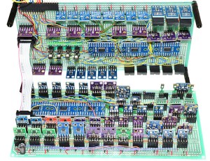
Just stumbled across this Humidity sensor shootout by kandersmith, along with a brilliant example of humidity sensor calibration work. The Bosch BME280 won easily as the most accurate. I also found this video about the TAHMO weather station, which is probably the sweetest sensor combination unit I’ve ever seen. And after seeing all that elegant work, I have to throw in a link to this perfboard monster over at the Louisville Hacker space; just to balance your weather station karma 🙂
Addendum 2017-05-08
IP68 2-way and 3-way junction boxes have recently fallen below $3 on ebay. My DIY waterproof connectors are more robust, but for quick connections to weather sensors, these cheap pre-made junctions might also do the trick.
Abstract:Existing methods for dynamic calibration of tipping-bucket rain gauges (TBRs) can be time consuming and labor intensive. A new automated dynamic calibration system has been developed to calibrate TBRs with minimal effort. The system consists of a programmable pump, datalogger, digital balance, and computer. Calibration is performed in two steps: 1) pump calibration and 2) rain gauge calibration. Pump calibration ensures precise control of water flow rates delivered to the rain gauge funnel; rain gauge calibration ensures precise conversion of bucket tip times to actual rainfall rates. Calibration of the pump and one rain gauge for 10 selected pump rates typically requires about 8 h. Data files generated during rain gauge calibration are used to compute rainfall intensities and amounts from a record of bucket tip times collected in the field. The system was tested using 5 types of commercial TBRs (15.2-, 20.3-, and 30.5-cm diameters; 0.1-, 0.2-, and 1.0-mm resolutions) and using 14 TBRs of a single type (20.3-cm diameter; 0.1-mm resolution). Ten pump rates ranging from 3 to 154 mL min21 were used to calibrate the TBRs and represented rainfall rates between 6 and 254 mm h21 depending on the rain gauge diameter. All pump calibration results were very linear with R2 values greater than 0.99. All rain gauges exhibited large nonlinear underestimation errors (between 5% and 29%) that decreased with increasing rain gauge resolution and increased with increasing rainfall rate, especially for rates greater than 50 mm h21. Calibration curves of bucket tip time against the reciprocal of the true pump rate for all rain gauges also were linear with R2 values of 0.99. Calibration data for the 14 rain gauges of the same type were very similar, as indicated by slope values that were within 14% of each other and ranged from about 367 to 417 s mm h21. The developed system can calibrate TBRs efficiently, accurately, and virtually unattended and could be modified for use with other rain gauge designs.
Note: My usual calibration procedure it to poke a small pin hole in an old milk jug, and then use a graduated cylinder to add 1 litre of water to the jug. Placing this on the funnel of a rain gauge gives a slow drip-feed that generally takes at least 20 minutes to feed the water through. Usually I set a tethered logger to pass the tip count for each minute through usb to the serial window on the arduino IDE. Adding those minute counts gives me both the tip total/1L and the rough amount of time taken by each test, with relatively good consistency. Of the many used rain gauges we’ve picked up over the years, I have yet to find even one that isn’t under reporting by at least 10%. It’s not unusual for a really old gauge to under-report by 20-25%, relative to the rating. Leveling is always critical, and the slower the test the better. With older gauges, I rarely move the adjustment stops (where the tippers impact) on older loggers even if the count is off, because that’s less of a risk than accidentally shearing the pin with a wrench.
Addendum 2017-06-24
Another dual unit deployment. The biggest problem at this site was birds perching on the sensor, causing spurious readings. Bird poop will also clog up the filter screens over time unless you add an extra debris snorkel under the main filter screen.
We’ve continued to pair small DIY climate stations with our underground monitoring sites. The drip based rain gauges are still going strong, and all of them have now had aluminum funnel upgrades. Since the interrupt counting code also works with traditional tipping-buckets, we’re happy to use those too, provided we can get a good deal for one on eBay. The minimum install records rainfall, barometric pressure and temp, but I’m hoping to add solar radiation & anemometer sensors on the next round of fieldwork so we can get some evapotranspiration data.
Addendum 2017-10-11
Just found a nice looking solar powered BME280 based sensor over at instructables. A nice little housing to accomodate a perfboard backplane. If you have a 3D printer, it’s worth keeping an eye on Thingverse, as there are a growing number of tipping buckets, wind gauges, etc there. Given how how quickly ABS degrades with full sun exposure, it’s probably easier to just print wind shields and debris screens for the cheap pre-made tipping buckets if you are working on a budget. Or perhaps print some mounts for solar cells, so you never have to worry about running out of juice while you capture the 433 MHz RF signal from an Acu-Rite 00866.
Given the dramatically lower power consumption, I will probably stick with hard wired interrupt methods for now. Earlier, I mentioned using attachInterrupt(1, rainInterruptFunc, LOW); to capture tipping bucket switch closures, but with more thought I’ve realized this could cause problems with other reed-switch based sensors such as wind sensors, which might stop with the magnet holding the switch permanently closed. In those cases it would probably be better to set the interrupt trigger to RISING, and this applies to Hall based sensors as well.
BME280 update 201903:to date all of our BME280’s have quit reading RH when exposed to outdoor environments. The general pattern is that the sensor operates normally for about two months, and if the humidity hits 100% regularly (say from rainstorms) the RH reading eventually just saturates at 100% and does not recover even after hot dry days. Pressure and temperature readings are unaffected by this, and those parts of the sensor continue to operate. Others have noted similar issues and this appears to be a common problem with other “capacitive” temperature-compensated humidity sensors. BME280 RH values are almost universally too high under warm and humid conditions. These problems may be related to how the temperature compensation algorithms work so it’s possible that libraries which give access to the cal coefficients might let you correct them to match “official” weather stations. But without better performance, these sensors simply aren’t suited for outdoor use, despite what is said about them by vendors. Might be better to go with a more expensive SensirionSHT3x series or a Honeywell sensor?
Addendum 2017-12-11
Though none of our field sensors are anywhere near a wifi / loRA network (or even a decent coffee shop), I’ve been keeping an eye on the growing number of ESP8266 microcontroller boards, as its pretty clear I will be playing with them sooner or later. Today I discovered that bigmessowires has pretty much covered all the things I had on my ESP wish list with his Weather Logger project. That is a pretty sweet setup for a home system.
Here a ring of cut zip ties is held in place with a pipe clamp, with the shower drain screen held w plumbers epoxy putty. If those cable ties don’t hold up to the sun exposure, I will cut some more durable bird spikes from old coat-hanger wire. I also keep an eye on the weather enthusiasts forum for other ideas like cut chicken wire.
Those drip rain gauges have been running alongside tipping bucket models for a few years now, and the results are quite comparable. However there has been one problem that has plagued all of our weather stations: Birdpoopclogging up the funnels because they always seem to drop berry seeds the size of the funnels exit hole. No matter which type of gauge you decide to deploy, add debris screens & snorkels and bird spikes to the design if you can’t get to the deployment site every four months to clear the wider main screens. A cheap DIY snorkel can be made with plumbers putty and shower drain hair catchers or aquarium pump shrimp-filter screens. It’s also reasonably easy to trim gutter filter foam into a working debris screen. Gutter foam might work better with the Misol ($18) & Lacrosse TX24U-IT ($17) tipping rain gauges, since they have a square profile but shower catchers should work fine with the round La Crosse TX58UN-IT ($20).
Addendum 2019-11-16
An interesting preprint over at EarthArxiv.org put me on to the Freestation initiative and the Trans-African Hydro-Meteorological Observatory . Freestation has a full set of sensor build plans that are worth a review by anyone creating a DIY weather station. A lot of very thoughtful work went into that project! These days you can buy relatively cheep La Crosse solar shields for temperature sensors. But they are plastic, and the shield I assembled (at the beginning of this post), only lasted about 1.5 years under the tropical sun before the paint pealed off, and the nylon struts became brittle enough to break. I suspect the 3-D prints would suffer the same fate in those conditions. After that experience I recommend the metal bolts & dog bowls method used by the Freestation project(photo right) for better durability. Of course you can go all the way to a full-sized Stevenson Screen if you’ve got the chops, and don’t forget to put conformal on everything.
However I’ve got to say that despite the ongoing IOT hype, wireless systems like this still seem too fragile for the multi-year deployments we generally aim for. Whenever I hear the term “base-station” it translates in my head as “single point of failure” and it’s worth remembering that theft & vandalism is one of the most significant causes of lost data in environmental monitoring. Then of course there’s the additional power requirements, which in this case only achieved 48h of run time on a 6000 mAh Lipo stack. For comparison, I consider our loggers “B” class if they can’t pass two years on a set of AA’s.
Addendum 2020-03-15: Adding Humidity Sensors
Looks like I’m not the only one frustrated by the general crappiness of capacitive humidity sensors. User liutyi over at arduino.cc has decided to survey the entire field of DIY sensors in his search for one that isn’t crap.
His summary:
DHT11 and DHT12 is not trusted in general absolutely.
AHT10 and AHT15 – also not trusted, slow and inaccurate, but maybe better than DHTxx
AM2320 – relatively not that bad (in compare to DHT and AHT)
BME280 and BME680 is always higher temperature and lower humidity (I suspect self-heating) I think those sensors are not for uncalibrated DIY projects)
HDC1080 – wrong (high) humidity
HDC2080 – wrong (high) temperature
SHT2x – OK
SHT3x – OK
SHTC1 and SHTC3 – OK
SHT85 – Perfect
This largely agrees with my own current impression that the SHT sensors have run the longest in the field, with several of the old SHT1x generation sensors giving us almost 3 years of data (w sintered metal shells) Those used the practical arduino library but they needed their own separate bus pins. They did not play well on the standard I2C lines because you only pull up the data & not SCL. Because SCL sleeps low, if you use a standard 4K7 on both lines like you would with a normal I2C device, you get excessive sleep currents.
The newer SHT30 generation seem to be working fine on ‘standard I2C’ with the sensirion driver available in the IDE. I’ve never tried one of the industrial market sensors like the T9602 for comparison.
Addendum 2022-09-23
We have over a dozen different Tip Rain gauges deployed, and they continue to be one of the most challenging sensors at remote stations that only get serviced once a year. Several of the gauges have manufacturer designed ‘snorkels’ but these often fail after hurricane winds throw debris into the air:
Gauge had standing water on our service visit.This gauge had a built-in debris snorkel, but the holes were to fine for this jungle location.
Fortunately our DIY ‘inverted drain screens’ approach has been performing well in a similar location:
Note the tinfoil protecting the logger from UV damage. Zip Tie bird spikes are only about 50% effective, but I dont have the heart to use metal wires…
This gauge was still recording well after 9 months of accumulation because of the larger elevated surface in the drain screen.A typical climate station from one of our projects. Two rain gauges for redundancy, firmly bolted to the cement block. Other sensors in the set are protected from UV & flying debris inside the stack of blocks. We do our best to find a rooftop unobstructed by taller trees, but sometimes you have to take what you can get. Perhaps the most important criterion is that the station must not be visible, as ‘tall monkeys’ will always be the biggest threat to your data in remote locations.


 I’m quite tickled about being able to replicate a task that you normally would need an oscilloscope to see. Of course my chances of actually catching one of those big unpredictable SD card latencies (from something like age related wear-leveling) is still pretty low, so I will continue to use this A544 method for solid longevity predictions.