
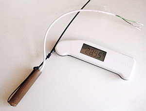
Without the dryer lint stuck in the end, the last digit on the Thermapen sometimes does not settle. I use the same thermometer for individual sensor calibration later on, but in that case it’s the DS18B20 probe that moves in and out of the copper sleeve, while the Thermapen stays in the Calibration Bath most of the time. The somewhat annoying folding off/on feature of the Thermopen design forces you to take it out of the bath every 10 minutes as the unit times out.
As I dive into another batch of cheap DS18B20’s for a new set of temperature strings, I thought I should post a note about the pre-filtering I do with these guys before investing effort to properly calibrate and epoxy them. After attaching crimp pins & assigning each sensor a serial number, I put several groups of them together in the water bath by binding them around a short length 1/2″ copper tube that has a felt plug at the bottom. The copper tube lets me keep the tip of a Reference Thermapen right in the center of the bunch. (The Thermapen has a resolution of 0.01°C & accuracy of±0.04°C – so not quite the ±0.01°C accuracy I should be using for my ±0.1°C target, but more affordable at ~$200 and it has a NIST traceable calibration certificate.) I cover the whole thing with towels for insulation, turn off the bath heater and, manually take reference readings every 1/2 hour as the water cools from about 40°C to around 10°C. I ignore the first few high temp readings as the bath convection stabilizes, and focus in on the curve at my temperature band of interest, which for the next deployment will be about 24°C. On a batch of about forty sensors, you see a spread something like this:

( Note: 12-bit values on left axis = 0.0625°C/LSB. The Thermapen reference line is the one with round markers, and has been converted to equivalent integer values)
These sensors usually tend to have stable offsets to within 1 LSB, so they group together naturally into ‘bands’ of 2pt high, 1pt high, 1pt low, etc. although they tend to toggle up or down over the length of the curve. I right-click on the lines and label the nodes with their behavior in Excel.
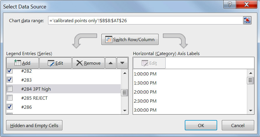
Once a sensor is labeled I hide it from view (by un-checking the box), so that I can click & label the remaining sensors. Once they are all roughly classified I bring up the sensors from each designated band to check if the high/low behavior of all the units in the group is stable over a larger section of the curve:
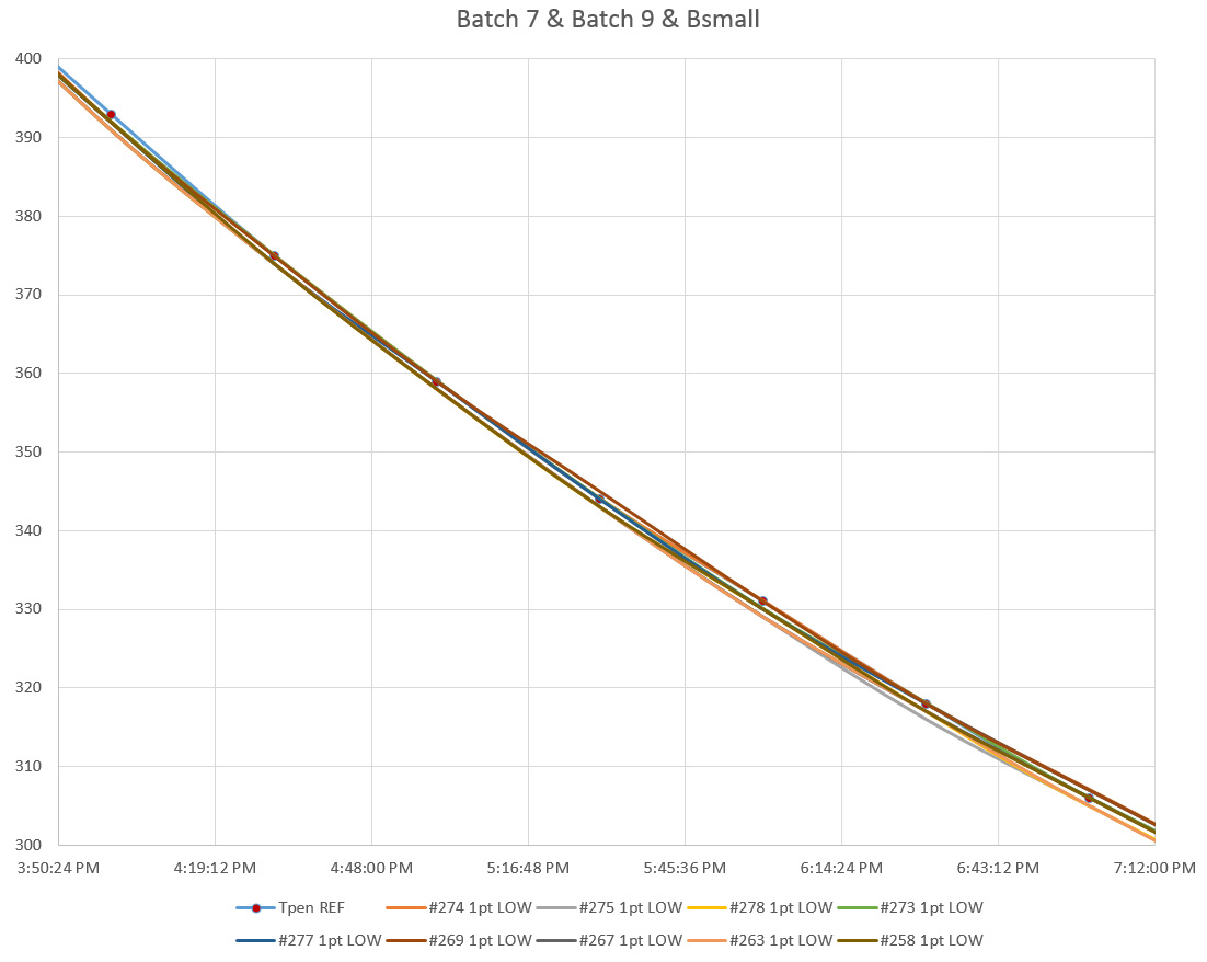
You can see here that some of the units that were 1pt low between 350-380 change over to 1pt high down around 300. And sometimes I move the sensors into a different bucket after looking a bit more closely at their behavior in Excel.
Those are the raw 12-bit integer readings, so the graph above covers from 18.75 – 37.5°C, and over that range you typically get about half of your sensors toggling within one LSB of the reference, with a further subset of about 8-10 that lie right on the reference line. If I can live with a spread of ±2 LSB (ie: ±0.12°C), my yield from this batch of sensors goes up to 31 out of the original 43. Given that these guys cost about $2.50 each, I just toss the rest into the bin before I do any further calibration. Occasionally, I get a bad batch where I triage around 50%. But the thing is, I invest so much time mounting these sensors, that I would still be doing a suite of tests like this no matter where I bought them. Time is the real cost when you build a logger with so many sensors connected to it.
Addendum 2016-02-15
If you want to do more than just eyeballing those graphs, a simple first pass is to subtract the RAW sensor reading from the 12-bit equivalent of your reference reading. Then take the average of those residuals as your bin category. (excluding high temperature outliers) This is still a pretty broad brush approximation of your sensor behavior though.
Of course once you get that far, you might as well plot the reference temps (Y axis) and the raw data (X axis) together and use Excel’s trend-line function to give you a correction equation that converts the sensor output into the reference:
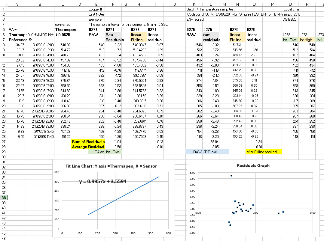
Note: The spreadsheet above (Click to embiggen) is in sensor output equivalent numbers rather than Celsius or Fahrenheit. It’s just faster to translate the reference data into sensor equivalent units, rather than change all the other numbers in the spreadsheet into stanard temperatures. But the units you decide to use does not change the method, just the constants you get for your trend-line equation.
Since the 20-30°C range is usually the flattest part of the DS18b20 response curve, a linear trend-line usually brings my average residuals below the sensors LSB resolution of 0.0625°C. In essence, this is a simple multi point calibration method that you could do with any reference thermometer and an insulated bucket of warm water.
If you have to go to a polynomial to get your residuals down in this temp range, you probably have a sensor that is going to be a pain in the backside to deal with. I always have bigger residuals at 30-40°C than I do at 20-30°C but that is also the part of the curve where the bath is cooling more quickly, so I suspect that I have hot and cold spots cropping up in the physical system. I’m now looking at adding a circulation pump, and perhaps making a dry well insert to put in the center of the bath.
This cooling ‘temperature ramp’ procedure is much different from the two point calibrations I was doing earlier, and I am still trying to determine which one gives better results when I combine it with the normalization that I usually apply to these sensor strings after they are epoxied into permanent sets. So far, the actual measured ice point offsets have not been agreeing very well with the intercepts predicted by regression on data from 20-30°C and that has me wondering whether it’s even worth the effort to calibrate these sensors over a temperature range that they won’t see in the field.

I insulate the heck out of the thing with towels, etc. so the normalization cooling takes at least 24 hours (usually closer to 2 days). I still take occasional Thermapen readings, but only to compare with the resulting average that I generate with the sensor data. Ideally, the corrected average should already have very good agreement with the reference readings… or something has gone wrong with my procedure…
For the ‘normalization’, I repeat the cooling water bath procedure above with the completed temperature chains assembled as they will be for a deployment. But instead of the Thermapen readings, I use the corrected average (using the equations from above) of all the sensor readings on the Y axis, to generate a second correction equation to apply to each sensors raw data to normalize them to each other. Unlike Craig at Yosemite Foothills, I use a second order polynomial for on this step. After that second correction is applied, any differences I see between sensors on the same chain should only be due only to a real differences in temperature.
Addendum 2016-02-16
Well it serves me right for counting my chickens. After a few more days putting these sensors through their paces, 11 more units have died or they have stopped reading temperatures below 15°C. I’ve been drying them on the radiators each night, and though we have a hot water system, I suspect the combination of daily soaking, and night time roasting, loosened the seals between the metal caps and the epoxy or did some other kind of damage. So now this latest batch is falling towards a 50% yield of sensors worth putting into the chain. Looking on the bright side, perhaps selecting sensors that can take more abuse is a good idea in the long run, even if it was done accidentally.
Addendum 2016-02-29
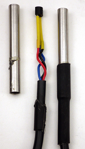
An air filled unit from eBay vendor nyplatform. Looking on the bright side, it’s very easy to extract the raw sensor if you wanted to.
After having a few more units die in the middle of testing it started to really get under my skin. So I decided to take a bunch of these sensors apart and soon discovered that many of them were poorly put together (no big surprise there…) I had assumed that the metal casings were completely filled with epoxy, but I soon discovered that many were sealed only with a bit of heat shrink tubing. So the thermal cycling I put them through on the radiators loosened it enough for them to soak through on their next dunking. Even when they had adhesive (like the unit shown on the right) they sometimes exhibited other strange problems as time went on such as not reading temperatures below 10°C so I have to wonder if the solder joints are also suffering from thermal expansion problems. Although the nyplatform sensors were the cleanest looking units inside, they suffered the highest failure rate, and had the largest raw residuals, often outside the ±0.5°C spec. So just being clean, does not necessarily mean best quality…
Things got even uglier as I moved on to the other vendor’s:
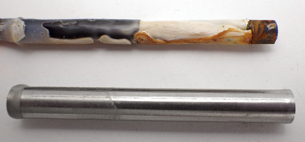
A DS18b20 from Electrodragon
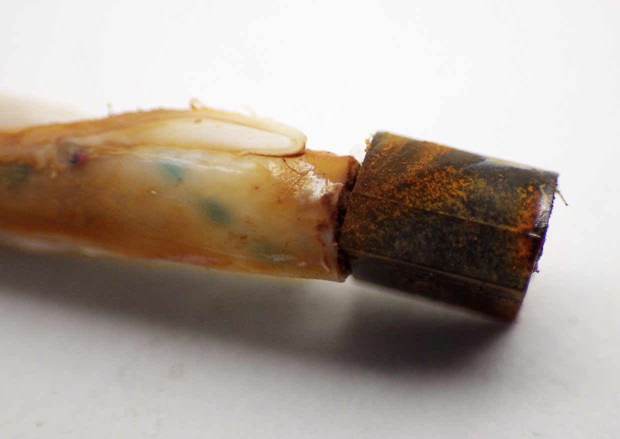
That just can’t be good…
Though the units from Electrodragon had at least some epoxy inside, they were still easy to simply pull away from the stainless sheath, and when I did that I discovered some nasty smelling chemistry going on in there. The frustrating thing about this is that during calibration runs these sensors were by far the best performers in terms of offsets & accuracy. But after seeing inside I have to wonder how long they are going to last. I have started pulling all of these units out of the metal and cleaning them with 90% IPA so that I can mount them directly inside the epoxy. Hopefully this treatment will halt that creeping decay and keep them running longer than they would have if I just left them as they were.
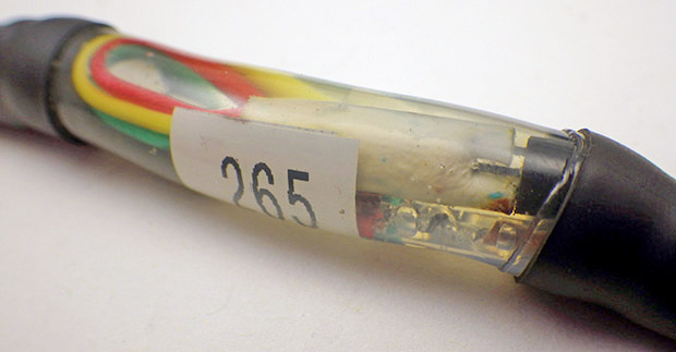
DS18b20 after cleaning & embedding in epoxy.
So I guess the take home of all this is that these cheap sensors should only be considered notionally waterproof in the same way that the round red things you buy at the supermarket in the middle of February are notionally tomatoes. Of course, once I strip them from the casing, they could be subjected to more pressure at depth, which had bad effects on my other temp sensors…Argh!
Addendum 2016-07-27
WordPress does not let me move comments from one post to another, so I am transposing this reader question over as an addendum:
João Farinha asks:Great Work, I’ve a question if you don’t mind. The length of probes DS18B20 are small and several times I had to make extensions, used single-wire cable (Ethernet cable), sometimes the probes stop to work as the union between cables is made with solder, did this ever happened to you? if I just wrap the wire to the other and put duct tape around works well but is not as solid.Cheers
I solder everything, and so far I have not had any problems with signal bounce on chains up to 25 m in length. But I do not use Ethernet cable, I use M12C Series Extension Cables from Omega.com as these are rugged enough for my underwater application. However I should mention that I have ruined several sensors in the past by having my soldering iron too hot when I tried to put the jumpers on the legs of naked DS18b20’s. I simply cooked them by taking too long. Wire wrapping could work if your leads were clean, but it takes practice, and a good tool for the job.
Generally I buy the waterproof units that already have 1-2m of wires connected (as pictured in the post above) since I need at at least short term waterproof capability to run the sensors through the overall calibration procedure before soldering them into a chain.

I enjoy your articles Ed, thanks for sharing.
Well I’m glad that my mum isn’t the only one reading this stuff! But seriously, one of the things that I can never find information about with Google is just how good or bad a given type of sensor actually is. All the old hands seem to say about clones in the forums is “Well, I would never use them…” but they don’t say anything quantitative about what you are actually getting yourself into. Using fairly tight selection criterion, I loose about 20% of my sensors, and that agrees with the sleep current criterion that I use to filter out other cheap modules like accelerometers. I’d love to do this test over again with the sensors from Adafruit as I suspect they would deliver more units within that ±1 LSB sweet spot, but just doing the experiment would set me back $430.00. To put that in perspective, that’s more than the Reference Thermapen, the two calibration water baths, and all of the sensors I used for this trial. That’s a fairly big difference when it’s coming out of your own pocket.
I’m trying to build a thermistor chain, so your posts are saving me as much time and grief as you spent figuring all these things out!
Glad I could help, but keep in mind that I am learning this stuff as I go along. So don’t be surprised if I am making some mistakes along the way. More folks use thermistors than DS18b20’s because you can potentially get much better resolution out of them, so there are plenty of other great projects you should look into, like the one at the Alaskan Permafrost Laboratory.
Hi, Ed I have been following your adventures for a feww years by now. Impressivestuff!
I stumbled over a new sensor from Maxim: The MAX30205 ,facory pricing: $1.60 per unit
High 0.1°C accuracy and 16-bit (0.00390625°C) temperature resolution easily meet design error budgets and clinical grade requirements
Low 2.7V to 3.3V supply range, 600µA (typ) conversion supply current and shutdown mode minimize power consumption
Lockup-protected I2C serial bus
Small 3mm x 3mm package minimizes footprint for wearable applications
I guess you would need breakout boards though…
Hannes
Turns out that Closed Cube sells the MAX30205 on a breakout board, along with the Si7051’s that I have been using as calibration refs. I’m really happy to see 0.1C accuracy sensors becoming more available, but I think I’m seeing evidence that they pick up an offset when they are potted in epoxy – possibly due to pressure as the compound contracts.