Monthly Archives: December 2014

Sleeping an MCP9808 on an Arduino based Pressure, Humidity & Temperature logger

As I gear up for the next round of fieldwork, I thought I would introduce the newest addition to the Cave Pearl lineup: A logger for Pressure, Relative Humidity, and Temperature

Left: MS5805-02, HTU, MCP9808  Right: MS5803-02, HTU ,TMP102

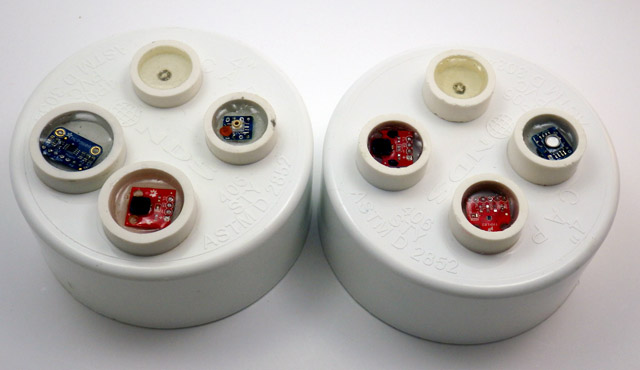
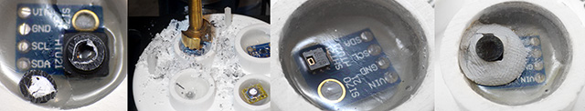
Left: MCP9808, HTDU21D, MS5805-02          [rgb LED on both]          Right: HTDU21D,  TMP102,  MS5803-02

When one of the drip sensors from the last deployment failed early, I went hunting for information to see if I could corroborate the dramatic increase in drip rate it recorded before it expired.

 The wires of the housing pass-through always push the boards into odd angles, so I level the boards with a preliminary 'underlayer" of cured epoxy while applying some top pressure with a pin to hold things in place

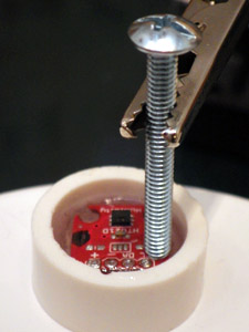
The pass-through wires push the breakout boards into odd angles, so I tack them down with a pea-sized bead of JB Plastic Weld while applying some top pressure to hold the board level. (takes ~15 minutes) Then I test the sensors “dry”, while they can still be removed. Potting in epoxy is the last step.

This made it clear that there really was not alot of good climate station data near our deployment site, and that even if that data was available, it still was not going to tell us much about the conditions down below. So I spent a couple of days cobbling together these mini “in-cave” sensor stations. I will try adding an anemometer to them them later, if I can find one that draws a low enough current to operate within my power budget.

These first units which will be co-deployed so that we can compare the performance of the different sensors. One uses the MS5803-02 sensor (already proven robust enough for five months at 5m in 50% marine water), and the other is using the much more affordable MS5805-02 which is only listed as ‘splash-proof”. This comparison is test was almost effortless to do, as both sensors are code compatible, with the exception of the CRC check.


CarefullyEpoxytheProtectiveCap

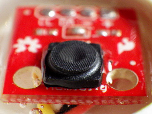
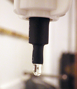
The cap fits because the HTU21D  from Measurement Specialties has a similar form factor  to the Sensirion SHT series humidity sensors. But you need to cut the legs off the cap to flush mount on the Sparkfun board as I have here.

For Relative humidity I am using the Sparkfun HTU21D with the Sensirion SF2 protective cap. The trick to installing these caps on the sparkfun board is to first bond the cap to the board with a tiny amount of epoxy applied all the way around the base of the protective cap with a toothpick. Once the cap is bonded to the board you can cover the rest of the topside of the breakout with epoxy, taking care not to let it run up to the protective fabric, where it could wick in and seal off the sensor. Hopefully this waterproof cap will protect the sensors well enough, but I am not expecting miracles because most RH sensors go a bit squirrly in caves, where the environment can be at 100% RH for a good deal of the time. I was very happy to discover that this sensor auto-sleeps after each reading, so it adds almost nothing to the power budget. The units are going into the field in a few days, so I will have to look at something like salt calibration of these humidity sensors later.

Good old JB plastiweld lets me tuck the Groove hub up out of the way, as all the real estate on my platform is taken up with the battery holders.

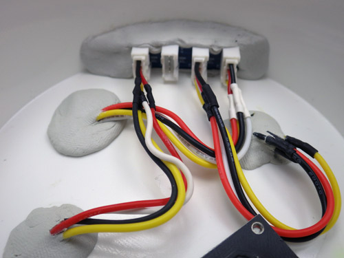
JB Plastic weld putty lets me tuck a trimmed Groove I2C hub up out of the way, so only one I2C jumper runs from the cap to the logger platform, taming the spaghetti monster.

For the hat-trick I am trying out two different I2C temperature sensors. Technically speaking, the pressure and RH sensors already collect temperature data, which they need for their internal calibration, but I just thought that it would be nice to do a little experiment comparing Sparkfuns TMP102 to Adafruits MCP9808.  While their precision is identical (0.0625 C), the 9808 claims much better accuracy.

I already had the TMP102’s working in one-shot mode, but even Adafruits generally good code support did not cover putting the MCP9808 into its low current shut-down mode, and this is critical for my application. A little browse through the datasheet, and it turned out to be pretty easy to do, and I thought I would post this for others wanting to use the MCP9808 for logging:

byte bytebuffer1 =0;
byte bytebuffer2 =0;
#define MCP9808_REG_CONFIG 0x01
//
void MCPshutdown() {
Wire.beginTransmission(MCP9808_I2CADDR);
Wire.write((uint8_t)MCP9808_REG_CONFIG);
Wire.endTransmission();
Wire.requestFrom(MCP9808_I2CADDR,2);
bytebuffer1 = Wire.read(); //upper bits first 15-8
bytebuffer2 = Wire.read(); //then bits 7-0//set “bit 8” to “1” to enter shut down mode
bytebuffer1 |= (1 << 0);
//x |= (1 << n); // forces nth bit of x to be 1. all other bits left alone
Wire.beginTransmission(MCP9808_I2CADDR);
Wire.write((uint8_t)MCP9808_REG_CONFIG); //register pointer
Wire.write(bytebuffer1); //
Wire.write(bytebuffer2); //this one is unchanged probably could skip it
Wire.endTransmission();
}
//
void MCPwakeup() {
Wire.beginTransmission(MCP9808_I2CADDR);
Wire.write((uint8_t)MCP9808_REG_CONFIG);
Wire.endTransmission();
Wire.requestFrom(MCP9808_I2CADDR,2);
bytebuffer1 = Wire.read(); //upper MSB bits 16-8
bytebuffer2 = Wire.read(); //then LSB bits 7-0//set bit 8 to 0 = Continuous conversion (power-up default)
// x &= ~(1 << n); // forces nth bit of x to be 0. all other bits left alone.
bytebuffer1 &= ~(1 << 0);
Wire.beginTransmission(MCP9808_I2CADDR);
Wire.write((uint8_t)MCP9808_REG_CONFIG); //register pointer
Wire.write(bytebuffer1);
Wire.write(bytebuffer2); //this one is unchanged probably could skip it
Wire.endTransmission();
}

Except for the bit-math, I use the same method here to wake up and shut down the sensor, but since the default values of the config register are all zeros, you could also use the much simpler:

void MCPwakeup() {
Wire.beginTransmission(MCP9808_I2CADDR);
Wire.write(MCP9808_REG_CONFIG); //register pointer
Wire.write(0b00000000);
Wire.endTransmission();
}

to reset all defaults & launch continuous measurement mode.  I think the soft reset does the same thing, but I have found that some sensors make you wait much longer after a “soft reset” before they give you good data than they do if you use a sleep/wake method. When possible I let my  sensors go through a couple of conversion cycles to flush old data out of the registers before I read them.

I have also learned some hard lessons about not trying to do calculations on a limited platform like the Arduino if I can avoid it. So all the sensor data is being saved as raw output in the log files.  I always get better results when I do the conversions later with a spreadsheet.

…And just to go completely over the top, I also record the temperature register of the DS3231 RTC. While this is certainly the least capable sensor in the mix, I am curious how it tracks against the others, in terms of accuracy.

Addendum 2015-02-27

As I put the first units into the field a couple of days after they were built, I did not have a chance to really play with them. So I recently built a couple more, using the TMP102 for temperature, MS5805-02 pressure sensors. One was built with the Sparkfun HTU21D breakout, while the other used a $5 noname HTU board from eBay.  In my tests so far, both deliver identical humidity readings, and both of these mini ultra based loggers sleep at 0.08 mA, which bodes well for these guys making it to my year of operation benchmark.

Addendum 2015-06-22

After building a few more of these I ran into a problem with epoxy wicking into the RH sensors before it cured. This is impossible to see under that SF2 protective cap so the only option is to drill out the bad sensor the next day. To prevent this from happening again, I now pot the RH sensor without the caps, and then tack the cap down with plumbers putty after the epoxy is dry:

Project Update: the Next Generation of Drip Sensors

It’s been a while since I made a post, as the basement workshop is in now in full swing assembling units for the next round of fieldwork. But I recently found out (thanks to Fernanda at Rio Secreto) that one of the drip sensors we installed in August croaked early, with a suspicious order of magnitude increase in the number of drips it recorded just before the battery took a nose dive:

Unit3_RioS_PowerCurveGraph_201400726-1010

Local climate stations don’t show that kind of increase in rainfall, and the batteries did not leak,  so my first thought is that the ADXL345 went through some kind of failure, self-triggering as it brought the whole unit down. But before that event, the battery voltage was good (I used lithium AA’s, which is why they started so high), so even with fake SD cards pulling alot of sleep current I think the other units will survive until we can retrieve them. To be honest, those first drip sensors were a dogs breakfast of different components, and most were cobbled together the week before the trip, so I am surprised that we only have one dead soldier so far. The fact that the data on the SD card survived a complete loss of power is also very good news.  I am actually looking forward to examining that unit, as it is the first hardware failure we have had in the field(I wish I could say the same thing for my code…)

Cave Pearl Drip Sensor Data Logger

With the usual quid pro quos of a highly variable duty cycle, this kind of sleep current might get me in to multi-year territory on 3 AA cells.

For the new set of builds, I have made a few changes to reduce the power consumption of the logging platform.   With a design goal of one year, continuous operation, I have decided to leave out the Pololu  switch, as it wastes too much power when you only have 3 AA’s. The Muve music SD cards from eBay have all been great low current sleepers, bringing my typical build with a Pro Mini clone board into the 0.25mA range. Powering the Vcc line on the RTC from a pin on the Arduino saves another 0.089 mA, and taking advantage of the MCP1700 on the Rocket Ultra brings my best builds down to 0.13mA  with a sleeping SD card (~ 60 µA) and an ADXL345 running (~ 50 µA) to provide interrupts.  Of course, there is always the chance that the RTC will not survive repeated switching on it’s power supply, so I will only test this technique on a couple of units in the next deployment.  If they survive without running the CR2032 coin cells dry, I will adopt this modification for the whole Cave Pearl line. It doesn’t sound like much, but that little RTC breakout will eat 600 mAh (1/4 of a AA) if you power it from Vcc for a year.

When you disconnect Vcc, the DS3231 goes into a 3uA timekeeping mode.

Here I have lifted the Vcc line from the RTC breakout board.  When this line is pulled low by the Arduino, the DS3231 goes into a 3uA timekeeping mode, saving 89uA

As a point of comparison, I tested an “unregulated” TinyDuino stack with the same code, SDcard, RTC, ADXL and battery pack, and it only went down to 0.55 mA while sleeping. Lifting the tiny light sensor board I2C lines, and having the SD card in place, means that the Tinyduino stack actually had two live voltage regulators, while my Rocket based loggers only have one. (Also, I don’t think they are pulling up the unused data lines on their SD shield, so floating pins might be increasing the SD sleep current a bit.)  And while having a regulator on every shield affects my particular application, I can see lots of good reasons for that aspect of their design. I still love the overall form factor of the TinyDuino’s, and the significant amounts time I spend soldering these loggers together has me patiently waiting for TinyCircuits to produce a generic voltage regulated, level shifted, I2C communications shield, so I could spend more of my time fixing code bugs instead of soldering (hint..hint!) It takes me about four hours to build one of these drip loggers from scratch.

I simply let the wires I am already using to tap the cascade port I2C lines poke up enough to give me solder points for the EEprom. Don't forget to remove the pullups on the EEprom board.

I simply let the wires I am already using to tap the I2C cascade port poke through as solder points for the EEprom.

The final upgrade in this iteration the addition of a 32K AT24C256 eeprom. With the testing I did back at the beginning of the project, I know there is a chance that this much I2C bus traffic (buffering up to 512 records if I fill the whole thing)  might not save much power, but it lets me standardize the data handling to one SD writing event per day no matter how many sensors are attached, or how short the sample interval is.  I will have a couple of the drip sensors buffering five days worth of data on the next deployment, to see if using this eeprom to condense five smaller SD card events into one big one  (which takes about 2 seconds to complete)  reduces the long term power consumption of the loggers. And finally, if the unit has a catastrophic power failure that completely toasts the SD card, there is a good chance that I will be able to retrieve the records buried in the eeprom for forensic analysis.

Having a second eeprom in the system also lets me “reserve” the little 4K AT24C32 on the RTC breakout for calibration data. While this is not that important for the drip sensors, it will come in quite handy as my flow sensors mature, and I start to tackle things like hard & soft iron correction on the magnetometer.  The drip loggers are so quick to make & deploy, they have become my low-risk test platform for new ideas.

Drip sensor test rig

Life was easier when I only had one calibration stand. Testing multiple units at the same time turns you into the proverbial man with two watches…

And speaking of test platforms, I now have two testing riggs set up for the drip loggers as they come off the bench, and they have taught me a very valuable lesson: Whenever you invent a new device, you also have to develop a new calibration protocol; which can turn out to be more challenging than building the actual device. Initially, I thought that all I would need for the job was a graduated cylinder and a funnel with some kind of flow limiter.  But my initial test results were all over the place, with the counts varying by 30% or more from one run to the next. At first I blamed the accelerometer thinking “It must be registering multiple counts, or it is just not firing the interrupt when it should”. I tried different sensitivity settings, varied timing delays, everything I could think of. But nothing seemed to improve the consistency between runs, and after many tests with crummy numbers, I was beginning to think I must be missing something fundamental.  I was so frustrated by this I decided to just sit there, staring at the little LED and counting the drops myself for as long as it took to figure this out… And I am really glad I did, because an hour into this caffeine powered exercise in utter boredom I had sore eyes, but I knew beyond shadow of a doubt that those sensors were working fine. Every drop was being counted. Every last one. So what was throwing the numbers?

Surface splatter from a drip impact. The green light is the LED indicating the count.

I made several attempts to capture photos the surface splash after a drip hits, as I thought this was throwing the counts off. Here you see the green LED light being triggered with five or six splash-drips flying away from the point of impact.

Google didn’t bail me out on this one, and all Wikipedia gave me was an article on how drip volume depended on the relationship between surface tension and tip radii.  But both funnels had the same 8mm pex tubing, hand polished smooth, as the drip source point, and they were still giving dramatically different results. It was time to call in the big guns, so I asked Trish to let me root around the Web of Science the next time I was at her office. That lead me to this paper:

Controls on water drop volume at speleothem drip sites:  An experimental study
by Christopher Collister and David Mattey, published in the Journal of Hydrology.

I used heat-shrink to get nice sharp 5mm diameter tube tip.

I  also used heat-shrink to make a much smaller  5mm  drip tube, further reducing the drip size.

In that paper there is a graph (pg 264) that illustrates: “At fast drip rates with drip intervals less than about 10s, drop volumes are seen to increase with a greater degree of scatter in the mass of individual drops.”  Their plot had almost 50% drip volume variability when the drip interval fell to 1 second. I had been testing my units at 3-6 drips per second or more, because I was worried about clipping the high end with all the delays I put in the code to prevent double counts from splash back. I also thought that with more runs, and larger the volumes of water (which increased pressure above the drip), I would be reducing the errors.  I went back with a magnifying glass, and sure enough, I could see the water surface tension shaking like a struck drum after each drip detached, and this wobbling increased dramatically with the rate of flow. Fortunately the paper also provided a solution to my problem:  “The results confirm that drop volumes are essentially constant at drip intervals greater 10 seconds.”  So I completely changed tactics, going for lower volumes and slower drip rates. On the very next try, I was getting data like this:

Unit 10: 500 mL
Drip Count: Time to complete: Drips/Min (max)
6289 135 min 62 dpm
6281 138 min 64 dpm
6314 141 min 63 dpm
Unit 10: 1000 mL
13097 246 min 70 dpm

At about one drip per second, I am still running these a bit fast. It will be a while before I get “ideal” interval tests done as they will take at least ten times longer to perform.  You can see how the larger 1000 mL volume pushed the flow rate up a bit, increasing the 500ml equivalent count up to 6548.  But even at 1 second intervals, I am pretty sure my handling of the graduated cylinder is on par with drip variation as a source of error. And the two different test rigs are within a couple of percent of each other now as well.

Whew!

Addendum 2014-12-02

Since the GSA, I have had people asking when I would have the drip counters for sale, and this post will likely trigger a few more enquiries. Right now every unit I can put together is earmarked for my wife’s research, or projects with other researchers who are helping me improve the overall design. So before that trickle becomes a flood, I should point out that plain old tipping bucket sensors are dirt cheap, and they are pretty easy to hook up to any arduino logger you can find (some people even hook them directly to bicycle speed loggers or calculators. And if you want it wireless, you can use a doorbell). There are some very interesting alternatives in the weather station station market (like the Hydreon RG-11, though at 15-50mA it’s a non starter for battery powered loggers) There are also plenty of lab-based drip counters out there that use approaches such as IR beam deflection or even photo interrupters / optoisolators.  A fair number of people are working on acoustic rain sensors. And finally there is already a drip counter on the market specifically for cave research: The Driptych Stalagmate. The Driptych uses a piezo sensor to detect the impact of the drips. While I have never seen one in person, I can guess that if they are able to use the voltage spike from the piezo to trigger the interrupt line directly, their loggers might be able to operate with an extremely low sustained power draw. In comparison, my accelerometer based approach will probably always pull at least 0.06 mA to keep the sensor ticking over, so I have a ways to go before I reach the four years of operating life they offer, not to mention all the other little bugs I still have to sort out. I am just having a heck of allot of fun doing it.

Addendum 2015-05-29

I recently tried replacing the accelerometers with some very sensitive 18020P shake switches. This removed the constant power drain of the accelerometer, but they also made it fiendishly difficult to adjust the sensitivity. Those simple vibration detectors are not standardized very well, so you have to rotate the switch in 3d space to find the best response angle for each individual one. (unlike the accelerometers, where its just a simple register setting) Tilt it a little too far and the switch will just self trigger, not far enough and you have to hit the thing very hard (relative to drip energy) to trigger the interrupt.  And when you have it in the right physical orientation for “light” drip impacts to register, the spring continues vibrating for quite a long time after receiving a “hard” drip impact.  Those “echo” triggers stretch well past 150-200ms, causing the problem that when the water is really flowing, and the drop volumes increase causing harder hits, the settling time gets longer and longer, so the sensor itself imposes a fairly low maximum detectable drip rate after which the spring mechanism is just triggering all the time.

<— Click here to continue reading the story—>