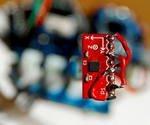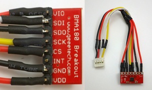
Plenty of these old geeetech breakouts selling on eBay. I know I am supposed to decouple VDD and VIO, but I have not figured out how to do that yet.
Up to this point I have been measuring displacement with the Bosch BMA250 on the Tiny-Circuits accelerometer board. But that sensor has a minimum range of 2g, using less than half of its 10 bit ADC in my tilt sensing application. Given that just about every electronic widget these days seems to rely on haptic feedback, I thought there would be a selection of other sensors out there to choose from in the 1 g range, so I was quite surprised to find out that there are only a couple of low g sensors on the market, and only the Bosch BMA180 uses an I2C interface. I was already using the 250, and that was pretty easy to get rolling, so I thought that it was going to be a piece of cake to switch over….
But the BMA180 is the gnarliest sensor I have worked on to date, with a spaghetti monster of co-dependent register settings, and an obtuse snarbuckle of a data sheet. But a 14bit ADC at 1g would almost triple the sensitivity of the Cave Pearls (In theory, registering a 0.25º tilt change), and for that I was willing to spend a week learning a bit about shift notation and masking to use this incredibly twitchy bit of kit. And reading data out of the registers is not even the biggest challenge: trade-offs between sensitivity and spiky random noise rapidly gets you into a tangle of offsets, sampling frequencies and filtering modes that don’t get explained at all well in the documentation.
I started out with general accelerometer references by Texas Instruments, and Freescale, which tend to focus on the calculations required to turn generic accelerometer readings into roll, pitch and yaw. From there I found a few BMA180 link pages, but most of the sites were for dedicated quadcopter IMU’s like the multiwii, which generally combine data from an accelerometer with that from a gyroscope, using complementary filters or more complicated Kalaman filter calculations. Most of these approaches are aimed at real time smoothing of continuous data streams, while I am interested in infrequent, high accuracy readings. There were a few seismometer projects, which showed me how to set the range, frequency & bandwidth filters, but they usually focus on getting interrupt alarm modes working, which is not useful for my application. Some mentioned calibration in passing, but there still was not much signal to noise optimization being done, and after several days I still could not find a single example of someone putting the sensor to sleep between readings to save power.
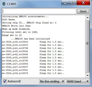
Once you start sending the readings to the serial monitor, you see how jumpy this sensor is just sitting on the desk, in low noise mode, with the lowest availiable bandwidth filter (10Hz). I tried a moving average with the arduino library, and then using a basic smoothing routine, but the readings were still pretty unstable. I finally managed to tame the gremlins with the digital smoothing method from Paul Badger, which throws away the high and low values from a set of readings, before averaging the rest of the data. The trade off here is that while this sensor only draws 1025µA in low noise mode, I have the whole system running for 1 second to capture enough readings for this process.
Given how tough it was to get this far, and how few people are using this accelerometer as a stand alone device, I though I would post the rough BMA180 accelerometer script which now produces reasonably stable 14 bit readings. The code has a nice function for dealing with individual register bits with a mask, which I am sure will come in handy for other sensors. I still don’t grok hex numbers, so I have written the masks as long form binary so I can see exactly which bits are being modified.
As I am using the BMA180’s default low-noise mode, I am simply relying on the factory calibration in the sensors ADC. But occasionally one of the readings will spike over 16384, so I know I still need to implement further offset calibration. I have already tried a few simple “high/low” methods, but most of them have actually made the x & y offsets worse (perhaps I need to use a jig for calibration?) and it will be a while before I can tackle least squares or gauss newton . To be honest, I am not even sure if its worth trying to attempt the 3D ellipsoid corrections on the Arduino’s cpu. (and I don’t know if my “organic” processor is up to the task either 🙂 )
Addendum 2014-11-04
I finally figured out how to get the BMA180 sensor sleeping to save power between readings:
// first check if the sensor is in sleep mode by looking at the content of bit1 in CTRL_reg0
// if so wake up the sensor by setting the sleep bit (bit1 of reg0) to “0”
// you do not need to set the ee_w bit before doing this!
// but the dis_wake_up bit must be “1” to disable the auto-sleeping function first
// (I do this in the initialization)
bytebuffer1 = i2c_readRegByte(BMA180_ADDRESS, BMA180_CMD_CTRL_REG0);
bytebuffer2=bytebuffer1;
bytebuffer1 &= B00000010; //knock out the other bits
if(bytebuffer1){ // if “true” then the bit was “1”
bytebuffer2 &=~ (1<<1); // forces 1st bit of bytebuffer2 to be 0. all other bits left alone
bytebuffer1 = i2c_writeRegByte(BMA180_ADDRESS, BMA180_CMD_CTRL_REG0, bytebuffer2);
delay(10);// now give the sensor some time to wake up
}
… now take your readings….
and then to put it to sleep again:
// put the BMA180 sensor to sleep again by setting the sleep = bit 1 of reg0, to “1”
bytebuffer1 = i2c_readRegByte(BMA180_ADDRESS, BMA180_CMD_CTRL_REG0);
bytebuffer1 |= (1<<1); // forces first bit of bytebuffer1 to be 1. all other bits left alone.
bytebuffer2 = i2c_writeRegByte(BMA180_ADDRESS, BMA180_CMD_CTRL_REG0, bytebuffer1);

Connecting to Vcc and GND further along the cable is easier than putting little jumpers on the surface of the board.
Because the sensor now sleeps below 1uA, I can let it run in its power hungry (~1mA) low noise mode when I need to take a reading, without having to worry about other power saving from things like the oddly named “wakeup” modes. The bitmath is from CosineKitty’s tutorial at the playground which showed me how to toggle just that one single bit in the register.

