This logger is a combination of inexpensive pre-made modules from the open-source Arduino ecosystem, and can usually be assembled by beginners in 1-2 hours.
Note: In 2020, we updated the design to reduce the overall build time. We’ve also added support to the code for using the indicator LED as a light sensor, so you can start monitoring the environment with the logger right away.
https://thecavepearlproject.org/2020/10/22/pro-mini-classroom-datalogger-2020-update/
If this is your first attempt at making a datalogger, then that new arrangement might be an easier place to to start than the tutorial set from 2015 shown below. The core components & their inter-connections are essentially the same.
The connection diagram for the Cave Pearl loggers follows this general pattern:

Note: This diagram uses the pin-outs of a Rocket Scream Ultra 8Mhz board with μSD adapter pin numbering convention per this document. I like the Ultras as they use a more efficient MCP1700 voltage regulator, but the whole point of the design is that you can build one of these loggers with any 3.3v ‘mini’ style board you can get your hands on simply by matching the connections to the pin labels [ Figure from: Cave Pearl Data Logger: A Flexible Arduino-Based Logging Platform for Long-Term Monitoring in Harsh Environments Sensors 2018, 18(2), 530; doi:10.3390/s18020530 ]

Note: A list of build parts & suppliers can be found HERE, and I will try to embed direct links into these instructions later.
Also Note: I posted a bare bones logger script for the UNO based logger tutorial on the project’s Github, and that is probably about the most minimal thing you can run on these loggers and it should be easy for folks to modify. To see a more developed code, with support for multiple different sensors, you can dig into the other code builds for the project.
And Also Note: In 2016 I posted an alternate build of this logger that uses Dupont style jumpers. It’s cheaper, takes about 1/3 less time to build, and is much easier for beginners to assemble. However the connections are not as robust as a soldered build, so if you are willing to pay the “iron price” the one shown here is better suited to rough & tumble of real world deployments.
After assembling more than fifty of these loggers, it now takes me about 4 hours (not counting epoxy cure time) to go from raw parts to a completely functioning logger. However, experience teaching other people how to make them has shown that if you can get your first one together in about 8 hours, you are doing great. Especially if you have never soldered before! The unit in the photo above was built with eBay parts for about $13, and the PVC housing in this tutorial will set you back another $8-10 (and not counting UART adapters, sensor breakout boards, or the tools you need like soldering irons or epoxy applicator guns). There are plenty of simple loggers out there in the $30 – $60 price range for things like temperature, pressure, etc., so the only reasons to build your own are 1) because you are doing something that is not already available on the market at a reasonable price (An example would be having your logger change it’s sampling frequency in response to interesting events: a feature like that is rare even at the high end of the market, though it is easy to do when you have access to the code) or 2) for the fun of doing it! And don’t underestimate that second one: few things are as addictive as getting beautiful time series data from equipment you built with your own hands.
My wire color conventions are:
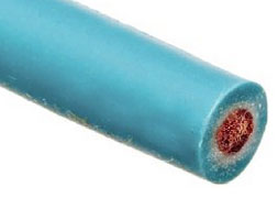
Red=positive power (both raw & regulated), Black=Ground, White=I2C Data, Yellow=I2C Clock, I usually use blue or green for interrupt signals, and other colors for the SD card SPI lines. I try to keep indicator LED leads the same color as the light they are controlling. I usually cut a bunch of 12cm wire segments and tin them all with a solder pot before starting a build. Adafruit has the best multi-strand 26awg silicone wire, but you can get by just fine with the 7-strand pvc stuff if the budget is tight.
Before starting:
Clean flux residue from breakout boards with 90% isopropyl alcohol. Ultrasonic cleaning in alcohol for 2x five minute sessions (outside & away from sources of ignition!) works well but you can also do it by hand with a Q-tips, etc. Brand name boards from reputable vendors like Adafruit or Sparkfun are usually very clean, but cheap knock-offs from eBay will be covered with goop that is guaranteed to corrode inside your loggers over time. Do not use ultrasonic cleaning on parts that are sensitive to vibration, like accelerometers, or you could damage them.
Component Preparation:
Each of the 3 main components is prepared with riser pins & jumper wires before the whole logger assembly takes place.
1) The Arduino ProMini style board
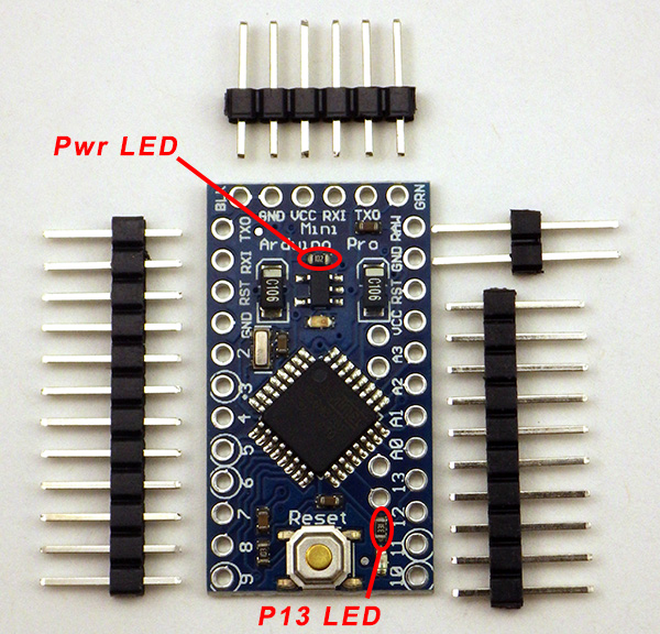 1. Remove the limit resistor for the power LED to disable it. Usually you can’t see these indicator lights because they are inside your data logger housings, so disabling the them will conserve battery power.
I usually also remove the limit resistor on the pin 13 indicator LED, although on your first build you should leave it there for testing purposes. My concern is that current drawn by the LED (because limit resistors vary from one board to the next) might interfere with SPI communications to the SD card.
 2. Solder the pin headers into place. Use two extra long pins for GND & RAW, and bend them 90 degrees under the Arduino board so that they protrude from the side of the board.
 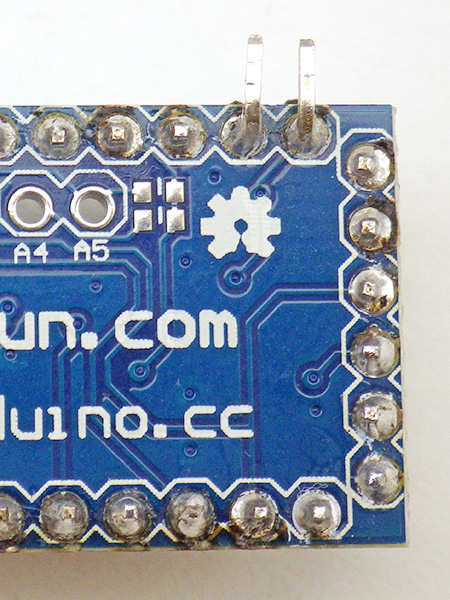 These under board connections will connect with the battery pack, leaving the vertical risers from the GND & RAW pins available for the connection of a resistor voltage divider to monitor the battery. I usually bend on the serial I/O pins slightly away from the other risers, just to make a little more room for connecting the UART boards.
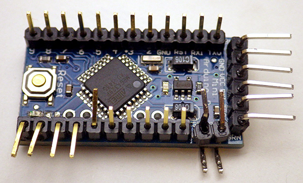 3. At this stage it makes sense to bend and add solder to several riser pins. Bend digital pins 10-13 away from the main board for later connection to the SD card wires. Bend pin A0, RAW & GND pins in toward the processor so that the battery voltage divider can be located above the board.
4. Then add solder all of the following riser pins to make connecting the jumper wires easier later on:
- A0 & vRAW & GND on one side of the board
- Vcc (3.3v), the other GND pin on the far side (you can never have to many ground connections!)
- D 10-13 where you will be joining the spi SD card jumper wires later
- D 2-9 (you may not use all of them, but it is much easier to tin those pins at this stage than doing after the logger is assembled)
- Sometimes I also tin the rest of the vertical pins in case I need to connect something to them later. This also depends on whether I plan on adding analog sensors to the logger.
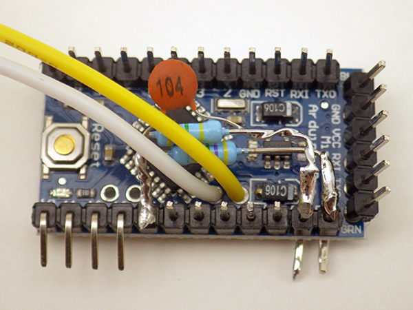
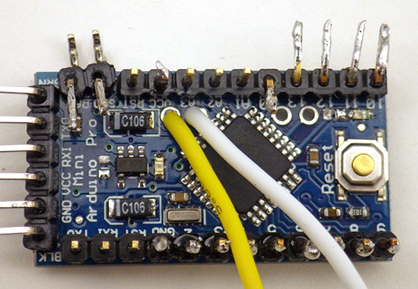 5. A4 & A5 are needed for the I2C bus, but on pro-mini style boards these are somewhat inconveniently located wrt the voltage divider we use to monitor the main battery status. Soldering a white jumper wire directly to the board at A4, and a yellow jumper wire to A5 allows us to breakout these connections. I usually strip, twist & pre-tin the wire ends before putting then through the board for these connections. Otherwise a stray bit of wire might not make it through the hole, and cause bridging problems.
6. Prepare two 4.7 Meg ohm resistors and 0.1 μF capacitor (code 104) as shown to form the battery monitoring voltage divider. The idea is to have this divider fit neatly within the board footprint as you connect to the appropriate the riser pins. Solder the end with all three together at A0.

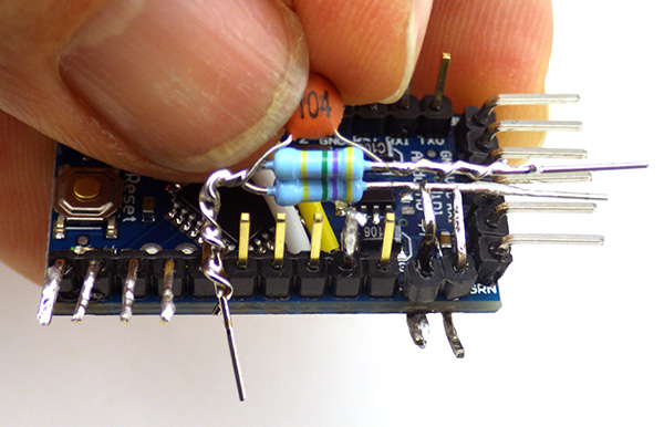
Be sure to use an ohm meter to find resistors with values as close to each other as possible before you solder them together. It’s easy to end up with two opposing % errors that throw off your battery reading even if they are from the same batch.
It is very important that there is an air gap between the RAW & GND leads of the voltage divider (on the right hand side), so that they DO NOT MAKE CONTACT with each other. This would short out your power supply! It might be a good idea to put some heat shrink in there too.
7. First solder the middle of the divider securely to pin A0. With that A0 connection in place, bend an ‘L’ into the lone resistor leg so that it lines up with the vRAW pin you bent and tinned earlier (ie: the one closest to the serial i/o pins). Try to get this connection fairly close to the Arduino board to make some room for the ground connection which will go above it. Then do the same procedure for the combined cap/resistor pin, soldering that onto the ground line riser pin. After the solder joints are in place, trim away the excess wire leads, being careful not to accidentally cut the riser pins.
Note: see this Jeelabs Post for more information on this method to track battery voltage
8. With the board level soldering finished, give the pin solder connections a thorough cleaning with 90% isopropyl alcohol to get rid of any flux residue. After drying, waterproof the Arduino board with a coating of silicone conformal coating (or nail polish) being careful not to get any on the risers or the reset button. Let the coating dry in a well ventilated area before proceeding to the next step. This coating is optional, but a good idea for electronics you are going to deploy in the field.
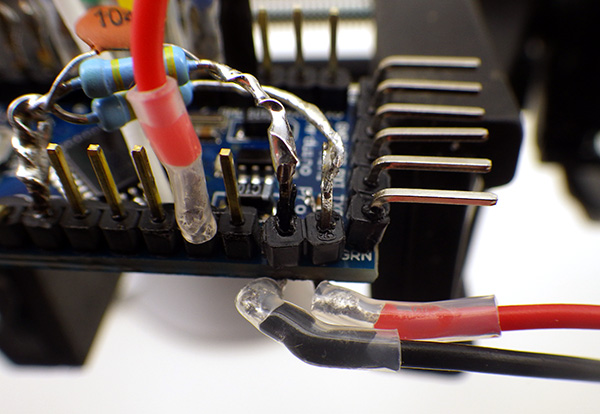
At this point you will be soldering some 3-4 inch jumper wires to the pre-tinned riser pins. 26AWG silicone jacket wire from Adafruit is my current favorite, but any thin multi-strand wire will do. I use thicker 20 or 22 gauge wire for the two battery power lines to make them more robust for the handling they see when the loggers are in use. Putting heat shrink over pin-jumper connections protects from accidental bridging when you place the logger platform into the housing. I advise that you use transparent tubing, as this makes it easier to spot a failed solder joint. Clear milspec 1/16”/1.5mm polyolefin heat shrink tubing is an excellent option, as it becomes very stiff when it cools, providing protection from flexing and holding a ‘bend’ in your wires that can help with cable routing.
 9. On the side with the voltage divider add a red jumper to the VCC pin. This is the 3.3v regulated power line that will provide power to all of your devices & sensors. Then add thicker battery connector wires to the two bent pins extending from below the board. Cut all your jumpers to about 4 inches, and TIN THE STRIPPED WIRE ENDS BEFORE YOU TRY TO SOLDER THEM to the riser pins. Having both sides of the connection already covered with solder before you bring them together makes it much easier to get a good connection. A cheap solder pot can be picked up from eBay for ~$15, which makes the stripping&tinning process much faster. Use a good quality no-clean flux.
 On the opposite side of the board:
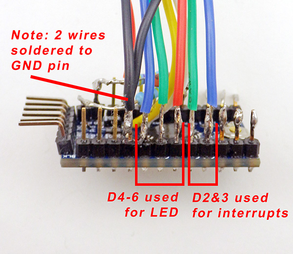
GND: Solder TWO black wires for the RTC & LED.
Pin 2: Interrupt wire for RTC alarm line (Blue)
Pin 3: Optional interrupt wire for certain sensors (Green)
Pin 4: Red power line for the RGB LED
Pin 5: Green power line for LED
Pin 6: Blue power line for LED
 10. After applying heat shrink tubing to the joints (optional), apply double sided tape to the bottom of the Arduino, in two layers. Cut the first layer so that it fits in between the stumps of the riser pins on the bottom of the board. Peel back the plastic backing on that first layer and apply a second layer of double sided tape that extends to the outer edges of the promini board.
 The Arduino is now ready for the logger assembly stage.
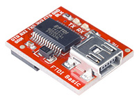
Note: This would be a good time to test whether the Arduino is working. Connect the pro-mini to a PC via a 3.3volt UART adapter and make sure that the ProMini board is selected in the IDE (Tools > Board > Pro or ProMini). You may have to specify the com port that your computer has given to the UART adapter (Tools > Port) and/or you may have to download a driver to support your serial communications board.
11. Run the Blink program (File > Examples > Basics > Blink) on Pin 13. Make sure to verify the program before uploading it. Assuming you did not remove the P13 limit resistor earlier, you’ll see the pin13 LED on the Arduino blink with one second intervals if everything is communicating properly and your Arduino is working.
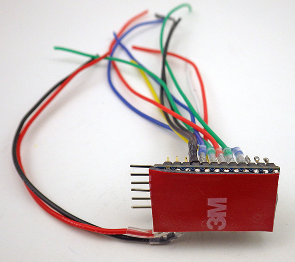
2) The micro SD card adapter
Four SPI signal wires will connect the SD card adapter to the Arduino board on digital pins 10-13. For these cut 2-3” lengths of four different colored wire. In this guide we used Orange, White, Green, and Gray wire. In addition, you will need red & black power wires, but these will not be routed to the Arduino. Instead they will tap the 3.3v regulated power and GND lines on the RTC adapter.
1. Flip the adapter board over and apply a thin coating of solder over each of the nine connector pads. Do not linger too long with the soldering iron making these connections, as heat conducted through the board may be enough to reflow the small contact springs soldered to other side of the adapter board. Usually if this occurs you hear a ‘snap’ sound while soldering. If this happens you may have to start over with a new board, as the adapter will not be able to make electrical contact with the inserted microSD card. I have found that the boards from Adafruit are reasonably resistant to this problem
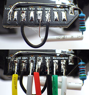
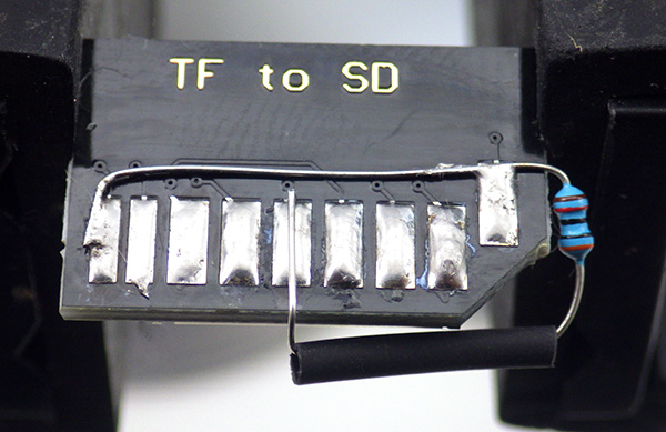 2. Then add a 30 – 50K pullup resistor to the two pads at the end of the board. These connections are not used when the Arduino is accessing the card in SPI mode, but if you leave them floating some SD cards draw excessive amounts of power in sleep mode. Solder one end of the resistor to connection 1, bending it 90 degrees and laying the lead wire across the board to the other pad. Be careful to route the resistor lead so that it does not come in contact with any other connection vias on your adapter board. Fold the resistor along the cut edge and solder the remaining end to connection in the middle of the board (which is the 3.3v power line) I often put shrink wrap over the exposed resistor lead. I am probably breaking some rule tying the unused DAT1 & DAT2 lines together like this, but it has been working ok over several years of operation at this point. Use two pullup resistors for this if you prefer.
 3. The ground line needs to be connected to the SD adapter board in two places. Cut another 1” of black wire. Strip, twist and solder the black wires together on one end and solder that joined connection to pad. With the two-wire end in place, cut the short jumper to length for the second pad, then strip and tin the wire end before bringing down to the other ground line pad. Note: Many of these uSD adapter boards already have the two ground pads connected with an internal jumper. In fact the one in this photo did, but I simply forgot to check for that with a meter before starting this tutorial.
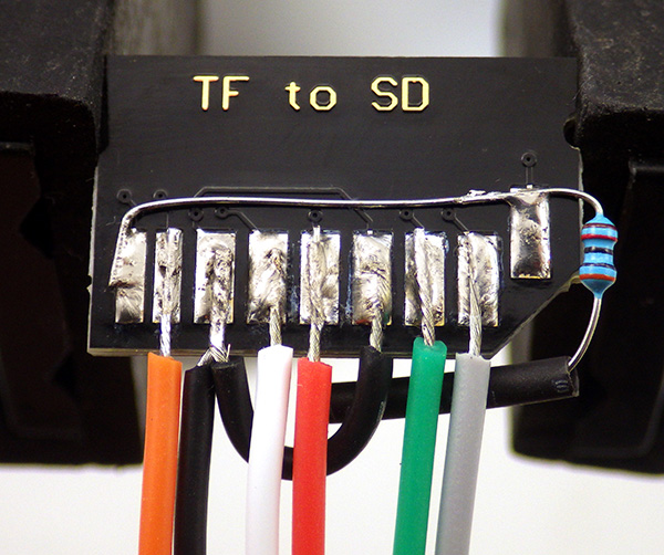
4. Add a red jumper wire to the pad in the center of the adapter with the pull-up resistor, being careful that you don’t unseat the pull-up resistor lead in the process. Then solder the remaining jumper leads in place. For this guide I have used:
 Orange at pad2 will be the spi MISO line and will connect to D12
- White at pad5 will be the spi SCLock line and will connect to D13
- Green at pad2 will be the spi MOSI line and will connect to D11
- Grey at pad1 will be the spi CSelect line and will connect to D10
- Black at pad6 with extra tail to pad 3, this will connect to the RTC GND pin
- Red at pad5 (with pullup resistor), this will connect to the RTC VCC pin
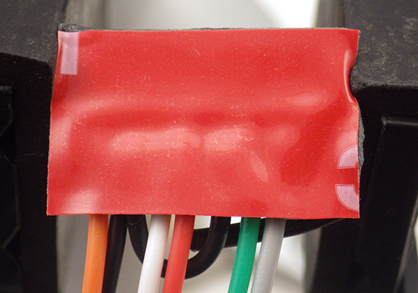 5. After the wires are soldered into place, clean away any flux residue with 90% isopropyl and let it dry. Be careful when applying silicone conformal coating to the soldered connections, as it may run to the other side of the board and coat the sprung SD connection springs, and prevent electrical connection. Make sure to dry it with the holder side up to prevent any liquid from getting inside the card holder. After the coating is dry, apply double sided tape to the SD card adapter.
Addendum:

Here is an example of the SD adapter modified with 30K pullups resistors on CS, MOSI & MISO. I used 1/8 watt metal films because their small size makes it easier to squeeze them in
Reliable sources recommend pullups on the SPI lines, though I have been running my loggers for a long time without them. I have noticed that some SD cards take a really long time to go to sleep unless CS, MOSI & MISO are pulled up, and some just refuse to sleep at all without the pullups. These weak pullup resistors are not described in this tutorial, but I suggest that you add them to your builds to sort out this problem with some cards.
If you already have loggers built without them, there is a workaround using the 328’s internal pull-up resistors that I current have in testing. Despite the fact that only CS requires it, I found that all three lines (w MISO set to INPUT not output!) had to be pulled up before misbehaving cards went to sleep properly. So add these lines to the beginning of your setup before you run sd.begin
// pulling up the SPI lines at the start of Setup
pinMode(chipSelect, OUTPUT); digitalWrite(chipSelect, HIGH); //pullup the CS pin
pinMode(MOSIpin, OUTPUT); digitalWrite(MOSIpin, HIGH);//pullup the MOSI pin
pinMode(MISOpin, INPUT); digitalWrite(MISOpin, HIGH); //pullup the MISO pin
delay(1);
I found that enabling these three internal 20K pullup resistors raises sleep current by between 1-5 μA, so it should not hurt your power budget, and could potentially save far more power by helping your SD cards go to sleep much faster. It’s worth noting that there is some debate about the necessity of this approach. Because SPI is a complex protocol, there are situations where adding physical pull-ups could actually interfere with other SPI sensors on your data logger, and in that case the internal pullups provide a more flexible option. That is one reason why I tend to stick to I2C & analog sensors on my builds, so the SPI lines are dedicated to the SD card.
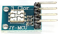
3) DS3231 RTC Breakout board
These cheap DS3231 boards usually arrive with quite a bit of flux residue that you may need to clean off of the board. There might also be a plastic tab on one end that can be removed.
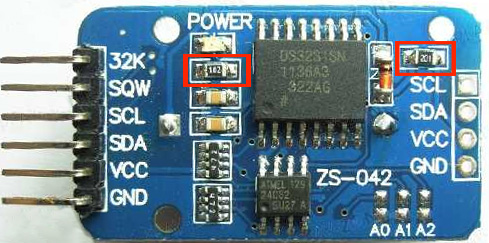 1. This board has a lithium battery charging circuit that can be disabled by removing as small surface mount resistor (201) on the right side of the board. The LED power indicator can be disabled by removing the (102) limiting resistor on the left side of the board.
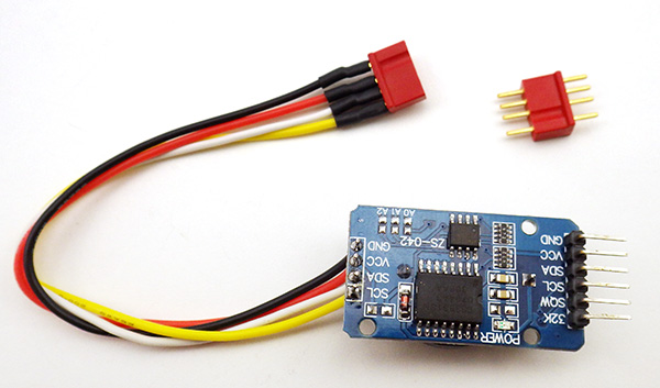
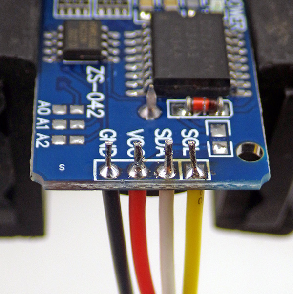 2. The I2C lines that we will attach to one side of this breakout board are provided on cascade connectors on the other side of the board with 4.7k pullup resistors already installed on the SDA and SCL lines. To that cascade connector solder 4” lengths of Black, Red, White, and Yellow wire on the GND, VCC, SDA, SCL respectively, so that they emerge the battery side of the board. Leave a few mm of wire protruding from the solder joins, as these provide convenient attachment points for an I2C EEprom if you wish to add that later.
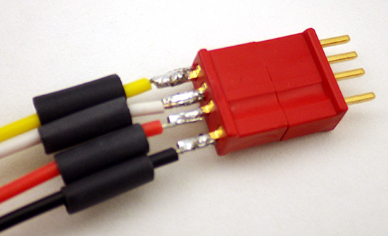 3. To the end of these four jumper wires add the four pin red WSD1242 Micro 4R Plug. Note the pattern used with the black GND wire on the dimpled side of the connector. (pattern: Y-W-R-Bl) Place the connector in a vise with the other side of the connector in place to prevent the pins from shifting when the thermoset plastic gets hot. Pre solder each pin, then cut, strip and tin each wire end BEFORE you try to join the wires to the pins. Thread the heat shrink tubing over the wires before you solder to the pins. BEFORE joining the wires to the connector in the pattern shown check that the female side of the connector is being soldered to the wires from the RTC.
As a general rule I always solder connectors in such a way that the side that is providing power is female. That way even when the connector is ‘live’ there are no exposed pins that could short out if the connector accidentally comes in contact with a metal surface.
Also note that there is nothing special about the Deans micro plugs I am using here, they are simply my current favorite after testing many others on the market. They stay secure with a good deal of knocking about, but at ~$1.50 per pair they are also pretty expensive, so feel free to substitute different connectors for your build. Dupont crimp connectors are much cheaper, and I used those successfully for quite a while before switching over to the Deans.
 4. Cover the IC side of the breakout board with a thin layer of conformal coating and insert a fresh CR2032 3V coin cell battery.
At this point the three core components of the logger are ready for the assembly stage. In Part 2 of the build instructions, we will cover connecting these parts together on a flat platform with the battery holders. And in Part 3 we look at assembling a waterproof housing. Part 4 covers techniques for optimizing your loggers power consumption, but some of them are more advanced so its probably a good idea to build a couple of the basic loggers before tackling the material in that last post.