

Doodling is a fundamental part of the process…
I spent a great deal of time cutting, sanding and gluing my underwater housings last year. And I learned a heck of allot about adhesives, O-rings, hull penetrations, and potting circuits. But mostly I learned that I like soldering more than I like cutting…sanding…and gluing PVC. Holiday travel left me with a wicked stomach flu on New Years, so I had a few bedridden days to contemplate all this and think about how I could simplify the design. I was already cutting up Formufit 2″ table caps to provide bolt supports on the 3″ housings, and I just had this sense that I was missing a trick by taking those table adapters apart just to glue the pieces back together again. Perhaps, if I made the build more compact, I could just use the Formufits as they were?
In all, I probably spent a week, staring into space and sketching ideas, and another week assembling prototypes. But I think I have finally sorted the new Cave Pearl underwater housing design for 2015. The taller unit here has six AA batteries, while the “mini” has only three:
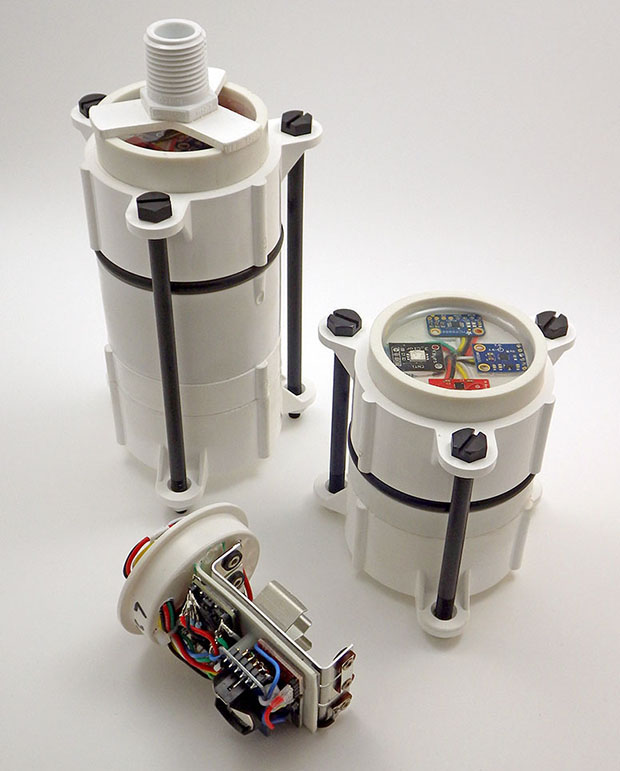
My wife dubbed these “Stormtroopers” because the black details against the white PVC reminded her of those Star Wars characters. Given how important actual storm events are to data they will be gathering, I’m cool with that 🙂
Boards are held in place with 3M double sided tape and the RTC breakout is inverted on 12mm M2 standoffs. This makes it easier to replace the coin cell on units where I power the RTC from a pin on the Arduino, since they will be in battery powered ‘timekeeping’ mode most of the time.
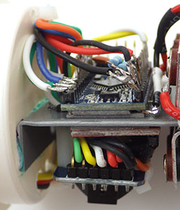
This assembly requires a small number of 2″ pipe cuts, and only two surfaces need to be wet-sanded for the o-ring seats. Putting all those sensor breakouts under epoxy in the single ring on top lets me juggle the them around, and is more forgiving of different board dimensions than my older designs. I would not have put that much faith in the Loctite E30CL if I had not already seen last years units survive for so long under water. This design requires a very tight build for the electronics, and I don’t think I could have tackled soldering like this when I created the original housings in 2014. Aside from the new 32k eeproms, this is still just a variation of the basic three component logger that I published in July last year. I am simply putting it together on both sides of a .060″ ABS sheet that I bend into shape with a heat gun.
Of course this new design will have to go through the usual round of underwater tests, and I hope that the long nylon bolts act as spoilers for the vortex shedding I am bound to see in the higher flow systems. I will add some rounded baffles if that becomes too much of a problem. Even if this design does not prove suitable for the flow meters, it is so quick to assemble that some version of this style will become the standard housing for my other underwater sensors. There are more variations coming off the bench, and I will post a few of the better ones as they come together, especially ones that let me flexibly extend the housing to hold more batteries for really long deployments.
Addendum 2015-02-06
This post has only been live for a few days, and I have already had several offline requests for more information. So here are some details on how I put these housings together, starting with an exploded view of the parts:

Only two surfaces (arrows) need to be wet-sanded for the O-ring seats. I take it to 800 grit, but 600 would probably be ok. Examine your parts before buying, as brands vary considerably in the number of casting seams & ID information they place on the rims. To do the least amount of sanding possible, buy the ones with the smoothest finishing, and flip your parts around so that you are not sanding down any edge cuts for o-ring seats.
The pipe is schedule 40 PVC, and the center piece is a standard 2″ coupling. The pvc ring bordered by the arrows is only glued on the coupling side, and it extends into the upper cap only far enough to provide a backer for the o-ring, and to hold the top cap in alignment. The top cap is not glued, but is held in place by the five inch 1/4-20 nylon hex bolts. These bolts are slightly wider than the holes in the Formufit endcaps, so you need to drill them out a bit. But I would suggest that people start their builds with threaded rod, rather than fixed length bolts, as this gives you the freedom to experiment with different lengths of pipe. The o-ring pictured here is a #332 3/16″width 2 3/8″ID x 2 3/4″OD, and its diameter extends slightly outside the PVC (pressure at depth will push them inwards…). A smaller diameter 1/8″-229 also works, and fits inside the seats. I am still trying to find an affordable supplier for 5/32″ cross section o-rings, which would probably be the best size to use. I use Loctite Hysol E-30CL to pot my electronics. I use the clear epoxy is so that I can see my indicator LED’s and keep track of how the epoxy is aging. But if you replaced that epoxied well of sensors with a clear acrylic disk, you could make camera & light housings for other interesting projects. The only limitations are that everything has to fit inside 2″ PVC pipe, and that those flat Formufit cap ends are only 4 mm thick, affecting the maximum depth they can with withstand. For now I am expecting these housings to go to at least 100ft/33m safely.
Addendum 2015-02-07
And here is the extendable version of the design:

Each bank of batteries is isolated with a 1N5819 Schottky. Just wait till you see what I need all this power for . . .
In this version the lower ring of struts (where the white nuts are attached to the 3.5 inch bolts) has the flat surface of the Formufit table cap removed with a hole saw. This turns it into a freely moving slip ring which applies pressure to the bottom of the glued coupling, and thus to the o-ring above it. This build uses a slightly shorter coupling than the initial builds, and the PVC tubing that leads to the rounded end-cap at the bottom can be any length, making room for more boards, etc. For multi-year deployments, I will probably make stand alone battery compartments this way, connecting them to a separate mcu & sensor housing via my diy underwater connectors.
Addendum 2015-07-23

The black zip tie (upper left) provides a handle so I can pull the carrier out of the housings.
I have discovered that the long temperature strings really did not need that 12 x AA whopper pictured above, and I now mount the batteries in a power pack module that is physically separate from logger itself. This gives me the added benefit that the batteries can be located further away from the sensor caps, hopefully reducing their influence on the magentometers I use in the flow sensor builds. If I suffer from battery leaks again, I can simply replace the carrier in the field. Should I end up needing a large number of batteries for something in the future, I will just whip up a “Y” adapter cable to connect a couple of these modules in a parallel configuration. The Schottky’s on each bank will keep them from fighting with each other.
Addendum 2015-07-26
And here is the exploded view of the parts for the extendable housing:

Once again only the indicated surfaces need to be sanded. The short 1cm ring and threaded adapter in the lower right corner are optional, depending on how you want to mount your sensors. I usually put at least one threaded connector on the body so that I can attach some sort anchor cables to my loggers at that point. The bolts are just a wee bit bigger than the holes in the Formufit caps – so you will have to drill them out with a 1/4″ bit to let the cap slide freely, and only use nylon if your sensors are sensitive to nearby metal – otherwise go with SS. The PVC coupling is 4cm wide, and if your couplings are longer the bolts will be too short, and you will need to switch to threaded rod.
Addendum 2016-03-10
 As more projects adopt this housing design, many have been asking me about the maximum depth they can withstand, though I have not yet had enough ‘spare’ units to put any through destructive testing. My back of the envelope guess? The 2″ schedule 40 pvc has a rated operating pressure around 150 psi, so nominally those parts are good to somewhere around 300 feet. So I am confident that we could deploy to about half that, expecting failures to occur first at the solvent welds & hull penetrations. (see pg 69 of the Loctite Plastics Bonding Guide for more info on shear strengths) You would probably need a harder o-ring compound for those depths as well, as the EPDM I am currently using is pretty soft, and would compress significantly below 100ft. For really deep deployments, you could fill the housing with oil like they do to the motors on ROV’s. Some of those add an ‘external bladder’ with extra oil to balance the internal and external pressure.
We no longer use those large surface area potting – rings shown at the beginning of this post because as you go deeper the epoxy begins to flex, and this ruined some of our temperature sensing IC’s. So keep the diameter of your sensor mounting wells as small as possible, and try to mount the sensors/leds etc. 10mm or more below the epoxy surface.
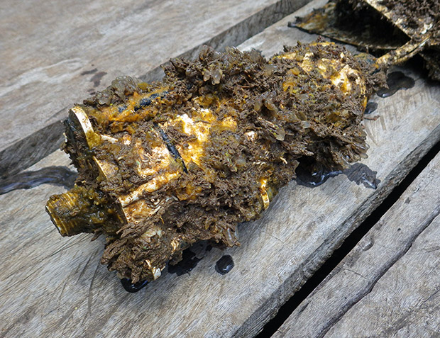
Bio fouling on estuary unit after 6 months. As you might expect, critters usually kill our pressure sensors before salt water corrosion does.
A researcher over in Europe contacted me while ago when I was using the 3″ end-caps, for a project tracking daily krill migration. But I have not heard back from him if he was able to go deeper with those thicker, rounded hulls. Our experience is that the PVC housings are unaffected by salt water, and although marine critters will grow on the surface, even boring organisms would rather drill into the loctite epoxy than go through the PVC housings. We often have to soak the loggers overnight in a muriatic acid solution to dissolve the encrustations before opening the housings.
Addendum 2016-07-31
I just stumbled across an interesting ROV build based on PVC pipe over at instructibles.com that shows just how far you can take this pipes & wires approach. PVC has been a go-to material in the DIY crowd for ages.
Addendum 2016-11-18
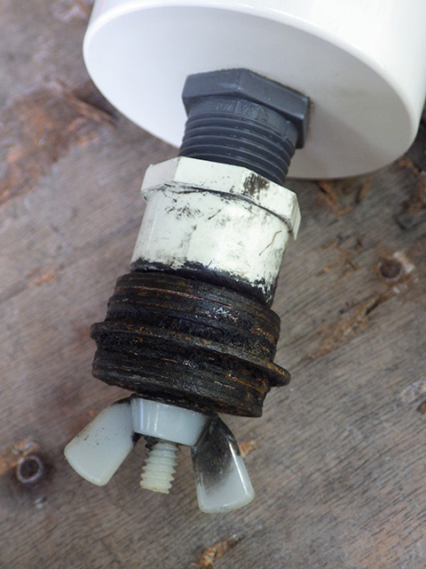
“Marine-Grade” 316 stainless steel washers after five months exposure to salt water – after scraping away the ball of brown rust. Whatever the company claims about it’s durability, always cut that number in half.
Just a quick note about those nylon bolts in that photo above. They expand from their dry length of 94mm to about 96mm when they are wet. This is just enough for them to become loose over a long underwater deployment unless you over-tighten them considerably going in. We’ve retrieved several loggers where the bolts that were tight when the units were dry, but could be spun freely when then logger came out of the water. Fortunately the sliding cap design means the O-rings were held shut by the pressure at depth so that seal saved us from data loss. Our magnetometer flow-sensors are sensitive to the presence of metal, but if your sensor combination is not limited by that I’d suggest you use stainless steel or titanium bolts to hold the housings together. Or at least soak those nylon bolts in water for a few days before deployment so they are already expanded. Note that the nuts also expand and are hard to release due to the increased diameter of the bolt when everything is wet – give them a day or so to dry out and they become much easier to undo.
Even stainless bolts corrode in seawater eventually, so lately we’ve been using SS bolts, with nylon nuts. That way even if the bolt threads are shot after a year (or two) in salt water, you can open your logger by cutting away the nut with a pair of clippers. Replacement bolts cost less than a fresh set of batteries, so you should probably add a new set of bolts whenever you change the AA cells.
Addendum 2020-03-01
A quick up date on the progress wrt hull pass-throughs: We’ve been using the sensor pigtails (described on the waterproof connector page) for quite a while now with connector dongles that are potted in E30CL epoxy on the housing body. But that’s overkill for shallow water & surface deployments. In those cases you can solvent weld threaded NPT connectors to the housing and attach the sensor dongle directly to the housing: (click to enlarge)
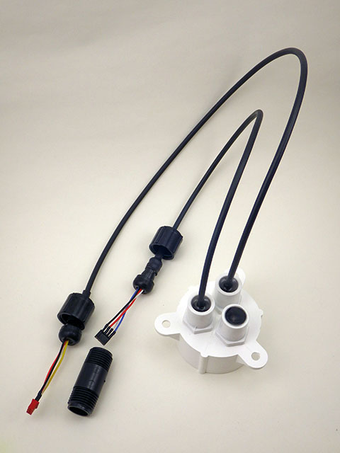 For deeper deployments where pressure is significant the hull pass-throughs are hardened with a thick well of epoxy. |
 For shallow/surface deployments: 1/2 inch threaded NPT connectors can be drilled allowing wires from the sensor dongle to pass through the bulkhead. |

Smaller housing made from only two caps (April 2020)
We do observe some pressure-bowing on the flat end-caps below 20m depth even when the wells are filled with epoxy. And since the 1/2 holes necessarily weaken the bulkhead I won’t be deploying direct-connect loggers past 10m if they are made from schedule 40 PVC. With recent advances in power management we’ve also been able to decrease the size of the entire housing. (w details at @ DIY data-logger Housing from PVC parts)
