Although the dive-light forums had convinced me to use PVC tubing as my housing material, I still had some significant design issues to work out. How big were these things going to be? How was I going to seal the unit under water? How was I going to actually install it in the caves? etc. I spent so much time rummaging through the plumbing isle looking at fittings, that the staff at my local hardware store were starting to run the other way whenever they saw me step over the threshold. And the ones I did capture, with my half baked story about what I was trying to do, had a kind of “There but for the grace of God go I…” expression creeping across their faces. Of course, after years of exposure from my own friends and family, I guess I am just used to it now 🙂
Anyway, I started out with three inch pvc pipe, for the simple reason that this had the smallest inner diameter that would hold my “alpha” Arduino Uno datalogger. But how was I going to  hold it together? Bolts? Bungees? I had seen plenty of latch clamps designs on the newer lights from Dive Rite, etc., but they all seemed to use machined rod stock with turned threads and special holder grooves for the O-rings. And this was more complicated than I wanted to go. Fortunately, while I was working this out, I came across a miniDV housing instructable with a really nice system for backing an O-ring on a pipe. I realized that my housing could use this idea, but I did not need any of the clear windows or other things that complicated his design. Yes!

4″ pipe rings over 3″ end caps formed the basis of my housings
In fact all I really needed was two end-caps and a short length of pipe and I would have something that presented a nice smooth profile to the water flowing around it. But to connect the latch clamps I would need much thicker walls, or the screws would puncture the housing. A bit more noodling around and I made the happy discovery that the inside diameter of 4″ pipe just barely goes over a 3″ pvc endcap, and the two solvent weld together nicely. Of course, hand sanding those matching faces down through to 600 grit took a while, but I was left with a nice smooth polish on the O-ring seats.

Getting those O-ring seats down to 600 grit takes quite a bit of sanding.
It took ages to find marine grade latch clamps, and I was surprised to find them costing $15 to $20 each. (After a great deal of time reading spec sheets, I found the cheapest clamps and O-rings at amazon – I will post a complete parts list for those later). So I had a basic “latch clamp & clam shell” idea percolating away. But how was I going to suspend this thing in the water column? Initially I had thought that I would simply run a bit of fishing line up to the float, but as I thought more about what the 3-axis accelerometer was actually doing, I realized that I could get much more than a simple tilt angle out of it:
If I could keep the unit from rotating, I would also get the direction of the water flow from the same sensor data! This realization was at the heart of the question of how to suspend the units inside the flooded caves.
So I need 180 degrees of freedom on the anchor points, but no rotation about that axis, or the direction information in the data would become meaningless as the sensor spun around. I suppose I could have just put a compass sensor in the unit and been done right there, but I had this sneaky feeling feeling that the problem could be solved more elegantly if I just burned a bit of midnight oil.

Corrosion had locked up some of our drip sensor tipping buckets a few years before.
I started making all sorts of gimbals with hinges, bent wires, rods, bolts, springs, tubes, you name it, and I probably tried it. Most of them worked too, but they tended to be fiddly looking things that depended on one or more bits of metal, and I knew from previous projects that corrosion was eventually going to do them in. I also had to figure out how to attach those pivot joints to stiff rods, of varying lengths, which then somehow connected to the housing itself. On top of that, the whole assembly would have to gracefully fit inside a suitcase. And finally, just to complicate things still more, whatever I came up with had to be easily assembled in a dark cave, with a divers cold fumbling hands.
Well this little nut took me a few weeks to crack, and with all the factors in play, it represented the most complicated thing I had tackled on the project to date. Especially with “easily repaired in the field” also echoing around inside my head.

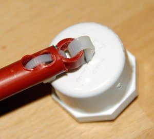
Pivot joint with no rotation
But I am happy to reveal here, for the first time, a bodgers masterpiece of simplicity made with two cable ties, a length of pex tubing (cut into a washer), and a threaded pvc cap. I can whip up one of these puppies in about five minutes, from parts at any hardware store, and the pex tubing, which bends easily into a suitcase, is just barely positive under water…and there are no metal parts. With this in hand it was full steam ahead, and as soon as the latch clamps & 3 inch O-rings arrived (341 EPDM 70A) I would be ready to start testing the alpha build.

Buoyancy testing
But I ran into a bit of a snag when I started doing dunk tests: I had not really counted on the extra mass of the latch clamps (20g each), so with my rough calculations, I hadn’t left enough internal volume. By the time I put my calibration mass (for the batteries, the Ardunio, etc) into the clam-shell, it sank like a stone. So I started drilling holes in the outer rings that the clamps were attached to, trying to increase the buoyancy so that the unit would just barely float when the simulated payload (about 220 grams) was inside it. The whole thing started to look like Swiss cheese.

One of the alpha housings, with anchor, and the short connector rod I made for the buoyancy testing.
Eventually, I ended up shaving most of the outer rings off the unit, which lead to several adhesion failures once the latch clamps started to apply pressure. But I just re-purposed those old shells into anchors with a rubber end cap. I had made a few shells, but I still had a pang of regret for the lost time, as I had spent more than an hour hand-sanding each of those O-ring seats. But the alpha housing build, minus electronics, was ready for testing. And just in time too, as this was early summer, and my wife had an undergrad about to leave for some fieldwork in Mexico. I made a few one meter support poles, stuffed the rest of the parts into a ziplock bag , and Trish passed this on to the student who flew out the very next day. I knew eyebrows might go up at the airport, but hopefully my weird collection of plumbing parts would not give the student too much grief from the airport security scanners. And even though the student was keen to help out, I knew that like anyone doing fieldwork, they already had a to do list that was larger than their available time. So there was a good chance they were not going be able to throw my contraption in the water and to see how it behaved.
I went back to developing the electronics side of things over the next couple of weeks, but I felt like a penny waiting for change each time I asked if the housing had been tested, and found out that, no, they had not had a chance to put it in the water. Not yet.
Then one morning over coffee, my wife says: “Oh, yeah. (the student) is back from her field work.”
My eyes widen, “And? Did the units go in? Did the floats respond to the water flow?”
“She put them in at one of the outflows along the coast” she replied, “And they seemed to respond to the direction of flow pretty well….”
“Mmmm, why do I hear a “But” coming…What actually happened?” I asked.
“She says that they wobbled.” and then she added,”Sort of wiggling around as they tilted in the direction of the current. But the flow’s pretty strong there, so it could have just been regular eddy currents. You see that in the seaweed along the bottom all the time…Then they sank.”
Trish wasn’t too worried about this news but I was a bit stunned. I had been expecting something like “it sank”, or “moved slowly”, or “no response at all”, but I was not prepared for “wiggly & wobbly”. I spent that morning in front of Google, trying to learn something about fluid dynamics, and specifically, the phenomenon of: “Bluff Body Vortex Shedding“. My heart was sinking with each new read because this had the potential to introduce so much noise in the accelerometer’s signal, that the data would be useless.
So we had run into a piece of fundamental physics that might kybosh the whole project. I was pretty bummed out that day, because even when I did start to understand the math, sort of, I still could not see any way around the problem. Fortunately for me, I was about to get some really good news on the electronics side of things, which had me doing my ‘happy dance’, which, on reflection, was probably a bit “wiggly & wobbly” too.
<—Click here to continue reading—>

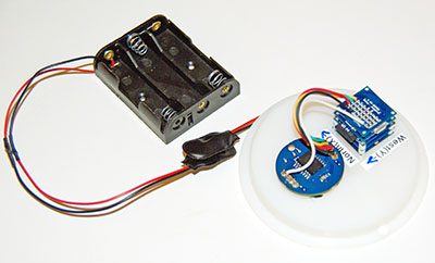 I’ve been doing run tests on the units over the last week or so taking samples every minute (simulating about 30 days in the field). Data logged well, but band-gap monitoring reported Vcc wobbling by more than half a volt once the supply fell below 3.8 volts. Not sure what to make the cutoff voltage though and I wonder if that monitoring code is a bit flaky? Even so, the accelerometer ran smoothly with very little noise on the axis readings during the wobbling voltages. But I did see a bit of downward drift in the internal temperatures being reported by the RTC, and the accelerometer. Not sure what caused that.
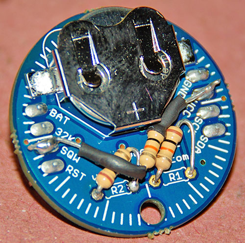


 I had used some
  cable ties through pvc plugs, and suspending them under the pipe clamp. This worked but it only heightened my concern about the nature of the seal on these puppies. You see traditional O-ring designs actually work better on deep dives, because the added water pressure compresses the o-rings more tightly. This new design was super simple to build but it was also critically dependent on not one, but two pipe clamps made of metal, as I had to balance the mass of the clamp screw. Even with marine grade stainless, I had my doubts about the longevity of that seal. Nonetheless, I pressed on, and thought about a scaffold for the batteries and sensor package. A bit of
  ply, some hard foam insulation, and a touch of gorilla glue (an adhesive on my top five list of bodging materials) produced a battery compartment and electronics platform under 25 grams. I added a ballast mass post with an old Ikea door pull, and put one of my new Tinyduino stacks into place. The hold down screws they came with were not long enough to penetrate that wood, so I had to fashion a U bend out of brass wire to affix the electronics.
 Eventually the “wobbly” enclosures made their way back to my workbench, and upon opening them I discovered that they had all leaked. But determined to improve the design, I scraped off the surface rust and began the post-mortem. Pressure from the latch clamps had actually separated the o-ring seats from the main body, damaging the o-rings. But it looked like I might have damaged the adhesion well before that, with all the grinding I had done in my quest for more buoyancy.

 I was really happy with the new housing, as the clips applied a nice even compression to the o-ring, and the overall unit just “felt right” to my divers hands. With the batteries held securely in place by a scaffold of Lego, the bucket buoyancy tests looked good, showing no torque from the uneven weight distribution that plagued the first builds. But it was riding pretty high in the water, and I need them to be “just barely positive” if they were going to respond well in low flow conditions. So I added a few ballast washers to both the top and bottom clam shells, and the Mark II housing was finally complete.


 batteries, and not a few of those were home made because that’s just how things were done in the early days. But the thing is, by the time we got them, those housings had already survived years of abuse, proving their worth. So I set off again rooting through the archives, for the “really old” dive light builder threads, which in the end, turned out to be

