Addendum 2019-01-15:
 I posted the $10 DIY Arduino data logger in July 2014, and there have been many updates to the way I assemble the basic three component logger since the early version described in 2014. In 2019 we updated the design to reduce the total build time to about 1 hour: https://thecavepearlproject.org/2019/02/21/easy-1-hour-pro-mini-classroom-datalogger-build-update-feb-2019/ We’ve also added support to the code for using the indicator LED as a light sensor, so you can start monitoring the environment right away :
In 2018 we published in Sensors: Cave Pearl Data Logger: A Flexible Arduino-Based Logging Platform for Long-Term Monitoring in Harsh Environments This paper describes how to optimize these loggers for long-term deployment and the PDF is free to download.
Original Post from 2014-07-01:
To celebrate Arduino day this year, Sparkfun put their 3.3v Pro Minis on sale for $3. Well, how could I resist that? I put in my order and, in due time, the little red boxes arrived with the morning mail. I was in the midst of assembling a small army of TinyDuino based logging platforms, so the Pro Minis just sat on the shelf for a while, as hacked into the tiny light sensor boards to drive my 3v sensors. But then, a couple of weeks ago, I stumbled across a project where someone had soldered a micro SD card adapter directly to the pins of a Pro Mini…What? I had at least half a dozen of those things lying around! Within minutes I was in the basement, waiting for the soldering iron to heat up and realizing that an onboard regulator meant that the RTC could also be connected directly to the board. Using 90° header pins to provide solder points at the base of the board (keeping the vertical pins free for sensors) I had the thing roughly connected in less than 30 minutes. A little scramble to re-jumper an old serial adapter I had in the drawer to run 3 volts (…because I forgot to order the 3v FTDI you need to use the Pro Minis), and the new unit worked like a charm right from the start. I had cobbled together a working data logger from only three components. I did a little cost estimation:
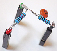
I used two 10Ks to divide the battery voltage in half & put it on A0. But you could use up to 2 x 10MΩ and bring leakage down to 0.3 µA with a small cap to stabilize the reading.
The Grove hub adds another $3, but it’s not really needed unless you are doing sensor swaps like I am. Otherwise the I2C sensors can just be soldered directly on to the other end of that RTC module. But I was still missing one piece of the puzzle: How do I track the battery voltage when I can’t use the internal 1.1v reference trick like I did with the TinyDuino? I googgled and found an excellent JeeLabs post about how to use a voltage divider to read supply voltages above Vcc on an analog pin. A little tweak to add the analog read to the Vcc read function in the codebase, and I had the cheapest “fully functional” data logger I have ever seen… sitting right in front of me.
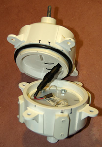
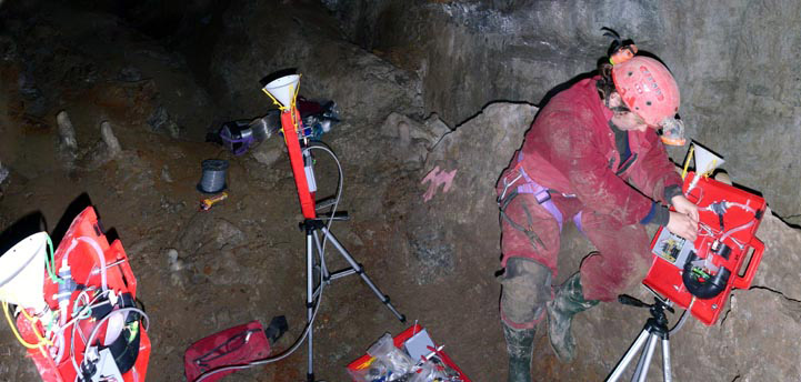
It didn’t take long for that moment of “Wait…did that just happen?” to have my brain hoping around like a bullfrog on a hotplate. You see, while this project originated with the challenge of determining water flow in cave systems, I hoped that there was at least the potential to do more than just keep my favorite hydro-geologist happy. Over the years we have worked with so many great people at various NGO’s, Eco-Centers, etc. plugging away with boundless spirit & enthusiasm, but hobbled by shoestring budgets. For these guys, something as expensive as a Hydrolab is just never going to be part of the game. But if you combine something as cheap as this Pro Mini based logger platform, with the super simple rubber bottom housings I came up with back in 2013:
 this unit survived ~ 4 months this unit survived ~ 4 months
@ 5m depth, 50% salt water. |
Fernco Qwik Cap
Nibco 3” pvc endcap
2x 3” knockout cap
4 x 2” 8-32 riser bolts
2x 3AA battery holders
3in of 3” dia pvc pipe
& ¾” pipe for sensor well
& pvc adhesive, etc., |
$3.50
$3.50
$0.60
$1.00
$1.00
.
.
$1.35 |
|
Total: |
$10.95 |
…then you have some real world environmental monitoring capability for about twenty five bucks. If you use this with I2C, or one wire sensors, you can sidestep the Arduino’s limited 10bit ADC, and get better data, with more frequent sampling than most, if not all , of the other low priced loggers on the market. (you could also use the ADS1015 12bit OpAmp/ADC combo board…) And because you have the ability to edit the code yourself, it is easy to track the rate of change and increase the sampling frequency during “events” of interest. Features like that don’t usually appear in commercial data-loggers until you start spending some serious money.
The only unknown at this point is how long this thing will run on a fresh set of batteries. On the bench this Pro Mini logger (with three sensors & 2x 10k voltage divider attached) draws about 1.8 mA while sleeping.* I figure ~2mA is going to chew through a standard alkaline battery (~2000mAh) in about a month, so a build with 6x AAs should be good for at least 3-4 months depending on the sample frequency. Most people are not working 30 minutes into a cave & 10 m under water, so that kind of retrieval schedule might be all right. Or one can make the pvc pipe a bit longer on that housing and have room for another battery pack, which should easily get you past 6 months. If you really want to splash out you could also go to lithium AA’s which provide an additional 1000 mAh per cell, and probably taking this thing up to a year on 9 cells…
As you might imagine, I have a couple of these loggers running on the bookshelf already, and I will post the burn test results here as soon as I have them. For now, I will simply post the wiring diagram, so anyone who wants to can build one. Just don’t take too long soldering the contacts on the micro SD card adapter, as you can melt through the plastic around them very quickly. I also suggest you test each stage of the wiring as you go along, before you finally attach everything to the platform…

Note: that several sources recommend pullups on CS, MOSI, MISO and SCK, though I have been running my loggers without them, but I have found that some SD cards take a very long time to go to sleep unless CS, MOSI & MISO are pulled up.
Read the Addendums below!: The Rocket Scream Mini Ultra is the lowest current board I have found so far & good SD cards are crucial to the success of your data logger. My latest builds based on this design usually get down to ~0.35 mA while sleeping. Recent field tests have shown that 3 good quality AA batteries will power a logger that draws 0.33mA for 9 months.
You can download my latest code to drive these loggers from the Cave Pearl Project GitHub. Just make sure you set the initial configuration defines properly before you compile (ie: uncomment ‘#define vRegulatedMCU 1’, and comment out ‘#define unregulatedMCU’ if you use a resistor divider to read Vbat…which you really have to do if you want the unit to gracefully power down when the batteries expire) Also note that depending on which sensor you connect, other changes to the code will be necessary to co-ordinate buffering, and formatting the data that gets written to the SD card.
So how does this affect the project?

Pro Mini power tests are now under way….( Update: read the Addendums -> Sparkfun Pro Mini’s gave me a host of problems with the SD card communications, while many cheap clone boards worked fine? )
The currently deployed Pearls are set to be retrieved in about a month, and if they deliver the same (> 1 year) power performance that the Betas did, I suspect I will be staying with the TinyDuinos for a while, at least for long term in-cave deployments. Just getting out to a remote cave site is often the most expensive part of field work, so if another fifty bucks worth of components means that I can safely wait a month or two (or six…) to find a flight deal, then I will ante up. But we already have people interested in using the Pearls for monitoring flows at springs and other open water locations. Most of them are on site, and they can service batteries by simply swimming out into the bay. So I think I will get those folks rolling with Pro Mini based loggers right from the start. It makes the build cheap enough that if some of these more exposed units “walk away on their own”, we wont be loosing our shirts. And it sends a tenner over to Sparkfun, without doubt one of the coolest nerd companies out there. As the Pro Minis are licensed boards, Sparkfun also passes on a bit of each sale to Mr. Banzi et. al., and that’s pretty good too.
<— Click here to continue reading—>
Addendum 2014-07-02
I have discovered that it is possible to run the Pro Mini’s without the on-board voltage regulators…in fact, so many people have been manually cutting the trace to the voltage regulator to get low power operation out of the ProMinis, that Sparkfun has now put a power isolation jumper right into the design. So if you get sensors that already have voltage regulators (as many IMUs do), or you use sensors that can handle large voltage swings (like the DS18B20) you could turn this pro mini based logger into something like the unregulated TinyDuinos that will operate for a very long time on couple of AA’s. You would still need to regulate & level shift the SD card lines for data logger operation so another alternative is to bypass the on-board regulators by simply connecting an alternate supply directly to Vcc. This is how the FTDI serial board powers your Arduino while you have it connected to the usb cable!
fatlib16 posted a picture (near the bottom of the thread) of his ProMini powered by an MCP1700 : you can bypass the on-board regulators by simply connecting the battery supply directly to Vcc -> this is how the FTDI serial board powers your Arduino while you have it connected to the usb cable!

I just discovered I should not be leaving those unused pins floating like I have in this photo – they should have pull-up resistors.
Addendum 2014-08-07
There are some very inexpensive Raspberry pi micro SD card adapters on the market now that are much easier to work with than the thin plastic SD card adapters I used on the first build. I suspect that the spring connectors are more physically robust as well. Of course you could try Adafruit’s adapter for $2.50, and if you had money to burn, you could go to the Sparkfun SD board.
Addendum 2014-08-11
Well serves me right for counting my chickens…After doing many different run tests on six different drip loggers built to this basic design I have some good news, and some bad news. The good news is that the cheap pro mini clone boards run well, logging data till they bring the power supply voltage low, at which point the voltage regulators go into a cycling reset loop, which so far has not hurt the data files on the SD cards. The bad news is that the units that have given me the most problems are…the ones that use the “real” Sparkfun Pro Mini. I still have not figured out why, but they have had no end of SD card problems. I don’t think its because too much current being drawn, as they are only 128mb cards, and the units seem to be able to write SD data when they connected to the 3.3v FTDI board, which can only deliver about 50mA in total. I will post an update when I get a handle on this problem…. (Note: later trials worked OK with other ProMini boards…these were just a bad batch. )
Addendum 2014-08-17
I have about a weeks worth of burn test data in hand from six different loggers built with this basic design. As I expected, the pro mini clone boards draw down a 3xAA power supply at almost the same rate no matter what the sample frequency is set to, indicating that the sleep current on the MC5205 voltage regulator they all use might the biggest load* on the system. (*This is an error – I found out later that the SD cards I was using were the real energy vampires. See below) From these rough tests it looks like I should get at least 3-4 months of operation out of them (on regular alkalines – 1/3 more with lithium) before the power supply gets down to the 3.35v minimum needed by the regulator. The best results so far have been from loggers built with the Rocket Scream Mini Ultra:
As I want to see how gracefully these voltage regulated systems behave when the batteries croak, I started the ultra based unit on a 3.4 volt power supply which already had a dead cell in it just to bring the voltage into the range of the voltage regulators minimum. More than 40000 SD card records later and the voltage is now at 3.3volts. I did nothing special to the board myself, just loaded the same code running on the clone board tests above, which makes liberal use of generic sleep code (ie: not using Rocket screams special libraries!) This thing is performing like one of my unregulated tiny-duino based systems. I will leave this unit running until the voltage divider reading vRaw gets to 2800 mv, (this might be a destructive test as this is way below the MCP1700T regulators minimum rating) because I still want to see how gracefully it handles a full brown out.
Addendum 2014-09-23
Just a quick update on the three component loggers. At this point I have put together about 20 of them with many different boards and they all seem to work OK (including the Sparkfun ProMini’s – Although they still give me more grief initializing the SD than the clones, even with the pin13 led removed. I just don’t know if their regulator is up to the task?). However I have found that the sleeping SD cards themselves are by far the most important part of the system, and that most builds come close to 0.3mA sleep current if you have REAL Sandisk memory cards…. However if you get burned with counterfeit cards your sleep currents can go above 5mA! Assuming your sensors don’t draw too much, with a 0.3 mA sleep current, a single AA battery could power one of these unit for a couple of months, and 3 AA’s should get you close to nine months. The big quid pro quo here is that nothing is protecting your SD card if you suffer a power failure. I’m working on that now. Making smaller individual data files is probably the first step.
Addendum 2014-09-27
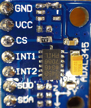
After more testing of the many 64, 128 & 256 mb cards I bought from eBay, and I have found that if you have the “good” Sandisk cards, the whole logger should gravitate towards about 0.33 mA, even if you leave connections 8 & 9 unconnected as I did in my earlier builds. (& I have an ADXL345 on my drip counter test system so about 40 µA of that current is being drawn by the sensor) However lots of my microSD cards seem to need pullups (OR pulldown) resistors on the two card connections that are not used to keep them from floating, or the sleep currents will be much higher. In the forums (and in the datasheets) people seems to be recommending 50-100K pullups, and I have done a few experiments which I will write up as a longer post later.
But the general result is: If this logger system+Sd card sleeps around 0.3mA with the pins floating, you already have a good card, pullups won’t change much, and about 1/2 the time it actually increases sleep current if you use a pull down resistor, possibly as high as 0.9 mA (the other half of the time the pulldown does not increase the sleep current). If your system draws between 0.5 mA to 2mA with the card sleeping…”generally” I find a pull down resistor on 8 &9 (I used 20k ohm) works better than a pullup, and should bring the whole system down to a stable 0.33 mA sleeping current. This is very strange because no where in the data sheets does it specify to use a pulldown. I probably need to do more testing here so I put a pullup on the illustration above just to be safe.
If you don’t get to near 0.33 mA with either a pullup or a pulldown, then you have a bad microSD card, and you should go find another one. If your “sleeping system” current for this logger design is above 2 mA, then you have a REALLY bad counterfeit microSD card, and you should just throw it in the rubbish bin. And the worst cards of all bounce down to a reasonably low sleep current initially, and then slowly “creep” upwards over the course of 2-10 of minutes, as you are watching the meter. Those cards often seem to be bad, whether you put a pullup, or a pulldown, on the unused lines so the card controller is probably NFG.
Generally, if you have a good card, it goes into sleep state almost instantly as soon as the MCU sleeps, and you can see that on the current meter because the numbers are completely stable at the lower reading right away. The crummy cards seem to wander around for a while, like they have to think about whether they actually want to go to sleep or not.
Addendum 2014-09-27
I have posted an updated version of this logger design. The new version adds a Pololu latching power switch, which allows the Arduino to cut its own power when the batteries fall low, protecting the data on the SD card. This is a real trade off because the switch itself draws as much current as the whole logger when sleeping, so you would have to go to six batteries to see 6-9 months of operation for that build. I have also provided links to sources of components have been using for my builds.
Addendum 2016-01-25
Reliable sources recommend pullups on the SPI lines, though I have been running my loggers for a long time without them. I have noticed that some SD cards take a really long time to go to sleep unless CS, MOSI & MISO are pulled up, and some just refuse to sleep at all without the pullups. These weak pullup resistors are not described in this tutorial. If you already have loggers built without them, there is a workaround using the 328’s internal pull-up resistors that I current have in testing. Despite the fact that only CS requires it, I found that all three lines had to be pulled up before misbehaving cards went to sleep properly. So add these lines to the beginning of your setup before you run sd.begin
// pulling up the SPI lines
pinMode(chipSelect, OUTPUT); digitalWrite(chipSelect, HIGH); //pullup the CS pin
pinMode(MOSIpin, OUTPUT); digitalWrite(MOSIpin, HIGH);//pullup the MOSI pin
pinMode(MISOpin, INPUT); digitalWrite(MISOpin, HIGH); //pullup the MISO pin
delay(1);
It’s worth noting that there is some debate about the utility of this approach. Because SPI is a complex protocol, adding internal or external pullups could actually prevent you from being able to use other SPI sensors with your data logger. That is one reason why I tend to stick to I2C & analog sensors on my builds, so the SPI lines are dedicated to the SD card only.

 While re-examination of the 2004 cave sensors has been on the back burner for a while, this drip counter was a direct result of my search for better tilt sensors for the flow meters. Those investigations lead me to several projects building DIY seismometers, and it occurred to me that if accelerometers were that sensitive, it might be possible to detect drips falling onto the housings. In the course of evaluating the ADXL345 (and rejecting it from the flow sensors due to relatively low bit depth at 2g) the well commented code posted by wyojustin & Kevin Stevenard introduced me to tap sensing registers. The “Eureka” moment that followed spurred on a week of furious prototyping, and this new drip counter is the result. I still have a bit of refining to do as I optimize timing & sensitivity settings, but as you can see from the video, the basic idea works down to around 10 cm fall distance. If I set the sensitivity high enough to catch drips closer than that the acclerometers internal noise starts to generate false positives.